Abstract— Wireless sensor networks have become a hot research theme in academia and as well as in industry in recent years due to its wide range of applications ranging from medical research to military. The IEEE 802.15.4 is the standard adopted for wireless sensor network platform. In this paper we study the effect of IEEE 802.15.4 MAC standard on the performance of AODV in a sensor environment with mobile Adhoc sink nodes. The sensor network should be pliant enough in nature to allow a systematic deployment of sensor nodes including mobility among the sink nodes. The disseminated data from the sensed nodes foregathers at the sink node. Data dissemination is the major source for energy consumption in a sensor network. Sensor nodes nearby to the sink disperse large amount of data to the sink with less energy consumption while the nodes far away from the sink require more energy to do the same. Hence, there is a need to investigate to see whether the dispersed data can be assimilated in vast quantity by moving the sink node to the region where large number of sensor nodes is emitting the sensed data. This leads to the question that, what is the maximum speed at which the sink nodes need to be moved? The mentioned scenario is simulated using Ns2 with WPAN extension which is an open source network simulator tool. An evaluation of IEEE 802.15.4 over AODV with sink mobility is carried out through variations in traffic load, packet size and number of source nodes. We have considered various metrics like Packet delivery ratio, Average Network Delay, Network Throughput and Normalized Routing Load for evaluation. From our simulative evaluation we show that the sink node velocity should be less than 1 m/s for obtaining acceptable performance.
Index Terms— Sensor Networks, IEEE 802.15.4, ZigBee, AODV, Performance, Sink Mobility
I. INTRODUCTION
Sensor network can be defined as a collection of wireless self configuring programmable multi-hop tiny devices which can bind to each other in an arbitrary manner, without the aid of any centralized administration, thereby dynamically sending the data to the intended recipient about the monitored phenomenon. By appropriately tuning the parameters of
1
Department of Electronics and Telecommunication Engineering, Jadavpur University, Kolkata 700032, West Bengal, India.
[email protected], [email protected]
2Department of Computer Science and Engineering, Acharya Institute of
Technology, Visvesvaraya Technological University, Belgaum 590004, Karnataka, India.
IEEE 802.15.4 it can be applied to a variety of applications. Research on sensor networks has been stimulated by the need of setting up the communication networks to gather information in situations where fixed infrastructure cannot be employed on the fly, as it occurs in the management of emergencies and disaster recovery [1, 2, 3].
In a sensor network thousands of sensor nodes are deployed in a random fashion. The Sensor nodes sense the phenomenon periodically and the sensed data is sent to the sink node. The information collected at the sink node is queried to extract the relevant information. In sensor networks by shortening the distance taken by the packets to reach the sink node, energy can be conserved. Mobility of sink may result in retrieving the data quickly [4].
The main contribution of this paper is that we have done a comprehensive analysis of the effect of IEEE 802.15.4 MAC protocol on the performance of AODV routing protocol in wireless sensor networks with mobile Adhoc sink. There has been no substantial work reported in evaluating IEEE 802.15.4 from an Adhoc mobile sink point of view.
The rest of the section is divided as follows: In the second section we present literature survey, in the third section a brief description of AODV routing protocol and IEEE 802.15.4 is given. Data gathering paradigm is discussed in section four. Simulation setup and analysis of the results are given in the fifth and sixth section. Finally we conclude our paper
II. RELATED WORK
The IEEE 802.15.4 standard was implemented by J.Zheng and M.J.Lee on the ns2 simulator and they carried out a comprehensive study of the 802.15.4 standard [5]. The authors conducted the simulation in both beacon and non-beacon enabled mode. The authors have tested various features like association, tree formation, network auto-configuration, orphaning and coordinator relocation.
Another implementation of IEEE 802.15.4 on NS2 was carried out by G.Lu et al. The authors have evaluated the star topology network scenario with a beacon enabled mode. The authors conclude that an extremely low duty cycle operation enables significant energy saving, but these savings come at the cost of high latency and low bandwidth [6].
In [7], the authors have evaluated the possibility of adopting AODV routing protocol over IEEE 802.15.4 in a mesh sensor network. The authors have proposed a new version of AODV routing protocol called NST-AODV, specially designed for sensor networks. Different implementation of AODV like AODVjr, AODVbis, LoWPAN-AODV LOAD, Tiny AODV has been discussed
Simulation Based Analysis of Mobile Sink
Speed in Wireless Sensor Networks
and compared with NST-AODV. It has been shown that NST-AODV reduces network delay and the number of retransmissions of the packets while increasing the network reliability.
The IEEE 802.15.4 based sensor network is evaluated with different topologies in [8]. The topologies considered are Ideal, fully connected topology, Non Ideal fully connected topology, Ideal star network topology and Non Ideal star network topology. Experimental setup is conducted in beacon and non beacon enabled mode. Following recommendations are provided by considering the amount of data delivered in each experimental setup a) If a node is not directly associated with a PAN coordinator then for such nodes the GTS should be enabled b) Flexibility in configuration of slots in a SuperFrame c) Even if a node is not associated with a PAN coordinator, still messages can be sent to those nodes by providing beacons to the PAN coordinator.
Under CSMA-CA mechanism and beacon enabled mode, the IEEE 802.15.4 has been investigated by considering Data Payload size, direct and indirect data transmissions [9]. Various concepts like Function devices, Network Topology, Superframe structures and CSMA-CA mechanisms have been discussed. Practical study of IEEE 802.15.4 has been conducted using CC2420 Chipcon devices with delivery ratio, throughput and RSSI as the metrics.
By default the number of back offs declared in CSMA-CA mechanism of IEEE 802.15.4 is 4. But in reality, the values supported ranges from 1 to 5. The authors have modified the default value and have evaluated the effect of having low backoff on 802.15.4. By simulation the authors have shown that less backoff mechanism leads to less power consumption and less latency [10]. In [11] also IEEE 802.15.4 has been evaluated with different backoff values and they have also proposed a “state transition scheme”. Here the minBE values are changed dynamically based on transmission schemes to make successful transmissions. In the state transmission scheme, a starting value of 3 (minBE) is considered for the nodes. But once there is data to be transferred then the value is changed to a lower value like 2. If the data transmission is successful, then again minBE is reduced to 1. If there is no data to be transmitted then again minBE is changed to 2. By applying this state transmission technique high throughput was achieved.
Evaluation of IEEE 802.15.4 with mobile sink is done in [12]. But the main difference between our paper and paper [12] is that they have not obtained the results by varying the mobility speed of the sink node against various traffic load, number of sources and number of nodes.
III. DESCRIPTION OF IEEE802.15.4 AND AODVROUTING PROTOCOLS IEEE 802.15.4 and Zigbee are industry standards designed to be used in low data rate, low power consumption, low cost and long lived networks. IEEE 802.15.4 is sometimes called as Zigbee even though Zigbee specifically refers to the routing protocol and 802.15.4 refers to the MAC and PHY protocols. The routing algorithms defined for use by Zigbee are the Ad-Hoc On Demand distance Vector (AODV) protocol and the Cluster Tree protocol.
A. Adhoc On Demand Distance Vector Routing Algorithm AODV routing protocol is an on demand routing protocol. To find a route to the destination, the source node floods the network with RouteRequest packets. The RouteRequest packets create temporary route entries for the reverse path through every node it passes in the network. When it reaches the destination a RouteReply is sent back through the same path the RouteRequest was transmitted. Every node maintains a route table entry which updates the route expiry time. A route is valid for the given expiry time, after which the route entry is deleted from the routing table. When ever a route is used to forward the data packet the route expiry time is updated to the current time plus the Active Route Timeout. An active neighbor node list is used by AODV at each node as a route entry to keep track of the neighboring nodes that are using the entry to route data packets. These nodes are notified with RouteError packets when the link to the next hop node is broken. Each such neighbor node, in turn, forwards the RouteError to its own list of active neighbors, thus invalidating all the routes using the broken link. [13, 14, 15]
[image:2.595.339.513.594.671.2]B. Low Rate Wireless Personal Area Network (LR-WPAN) IEEE 802.15.4 is a Low Rate Personal Wireless Area Network standard. IEEE 802.15.4 works in three different frequency bands – 868 MHz band working at a data rate of 20 kbps, 915 MHz band working at a data rate of 40 kbps and 2.4 GHz band working at a data rate of 250 kbps. Different topologies supported in IEEE 802.15.4 are star topology or peer to peer network or a cluster tree network. In IEEE 802.15.4 standard 14 PHY and 35 MAC Primitives have been defined. A device can be either a Fully Function device or a Reduced Function device. Any device that is not a co-coordinator is an end node. Fully Function Device (FFD) can act as a PAN Coordinator, a Coordinator, or just as an end node (device). FFD also functions as a routing device for grid topologies and for peer to peer communications. Reduced Function Device (RFD) has a reduced set of functionality which can only function as an end device or node. It does not have the ability to communicate with any other device other than the coordinator. A simplistic sensor network is made up by a mixture of these devices. But the basic rule is that any PAN network should have at least one FFD, to act as the PAN-Coordinator or a sink node.
Figure 1. Superframe Structure of IEEE 802.15.4 in an Beacon Enabled mode [from reference 16]
A superframe structure in a beacon enabled mode is as shown in fig 1. The superframe has a beacon on either side of the structure. Active and an optional inactive period follow the starting beacon. During active period communication takes place. The Superframe Order (SO) and the Beacon Order (BO) determines the superframe structure. The SO is the variable which is used to determine the length of the superframe duration (aBaseSuperframeDuratio
2SO).Similarly the Beacon Interval (aBaseSuperframeDuration
2BO) is determined by thevariable BO. 0
SO
14 0
BO
14 [image:3.595.331.521.190.308.2]When BO=14 then there are no beacon transmissions. An inactive portion is denoted in two situations, when the beacon interval is same as that of the superframe duration (SO = BO) and when beacon order is greater than superframe order.
Figure 2. Data Transmission in Beacon Enabled Mode [from reference 17]
Data Transmission can occur from coordinator to device (fig 2(a)) and from device to coordinator (fig 2(b)). Coordinator to device data transmission is as follows. If there is any pending data then it is indicated by the coordinator in the beacon. Then the device listens for the beacon. If there is any data pending, then the device requests for the data through the slotted CSMA-CA. On receiving the request, the coordinator acknowledges for data request and sends the requested data through slotted CSMA-CA. Device to coordinator data transmission takes place as follows. The device first listens for any available beacons. If it so then the device synchronizes itself with the superframe structure. Using slotted CSMA-CA mechanism the data is sent to the coordinator by the device. The coordinator then sends an optional acknowledgement packet. [16, 17, 18, 19]
IV. DATA GATHERING PARADIGM
The wireless sensor network is modeled as a directed graph
G
V
,
E
, whereV
is the set of nodes andE
is the set of directed wireless links. LetS
S denote the set of sensor nodes andS
c denotes the sink node or the coordinator node. Then,V
S
s
S
c. The transmission range for each sensor node is designated byr
tx. Letd
ij denote the distance between nodei
and nodej
. A directed [image:3.595.55.285.285.415.2]transmission link
i,
j
E
exists ifd
ij
r
tx . All transmission links are assumed to be symmetrical, wheree
ij
e
ji. A grid network topology as illustrated in fig 4 (A 5 X 5 grid topology with 24 sensor nodes and one sink node) is considered for our study. In the grid topology pattern, each of nodes can communicate with either horizontal nodes or the vertical nodes. A portray of this assumption is shown through the communication links in fig 3.Figure 3. A 5x5 Grid Network Topology
But, if a mobile sink is within the communication range of any node in any direction while it is moving, then communication takes place in that direction. Each of the nodes in the sensor network is beacon enabled with slotted CSMA/CA mechanism. Each of these coordinators is fully functional routing devices, allowing data transfer among each of the devices. The sensor nodes participate in the network through out the simulation time. AODV is the underlying protocol for routing the data packets. Compeer communication takes place in sensor networks among various nodes for routing the data to the sink node.
V. SIMULATION ENVIRONMENT
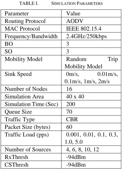
TABLE I. SIMULATION PARAMETERS
Parameter Value Routing Protocol AODV
MAC Protocol IEEE 802.15.4 Frequency/Bandwidth 2.4GHz/250kbps BO 3 SO 3 Mobility Model Random Trip
Mobility Model
Sink Speed 0m/s, 0.01m/s,
0.1m/s, 1m/s, 2m/s Number of Nodes 16
Simulation Area 40 x 40 Simulation Time (Sec) 200
Queue Size 70
Traffic Type CBR
Packet Size (bytes) 60
Traffic Load (pps) 0.001, 0.01, 0.1, 0.3, 1.0, 5.0
Number of Sources 4, 6, 8, 10, 12
RxThresh -94dBm CSThresh -94dBm
We have selected following metrics for evaluating the effect of IEEE 802.15.4 over AODV for Wireless Sensor Networks:
Packet Delivery Ratio to SINK: It is defined as
ets
ntDataPack
NumberofSe
Packets
ceivedData
Numberof
Re
The greater the packet delivery ratio is, the more reliable the network is.
Average Network Delay: It can be defined as
ionPairs
rofConnect
TotalNumbe
Time
Time
packetarrive dest packetsent source
@ @Throughput of the network: Throughput can be defined as the
rofNodes
TotalNumbe
ion
aTransmiss
hputsofDat
NodeThroug
A high network throughput indicates a small error rate for packet transmission and a low level for contention in the network.
Normalised Routing Load: The number of routing packets “transmitted” per data packet “delivered” at the destination. It is the sum of all the control packets sent by all the sensor nodes in the network to discover and maintain routes to the SINK node.
VI. RESULT ANALYSIS
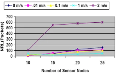
Besides running independently, all the simulations are averaged for 5 different seeds. Energy is uniformly distributed among all the sensor nodes. Simulations are carried out in a beacon enabled mode. All devices act as coordinator. We have considered different mobile speeds, 0 m/s, 0.01 m/s, 0.1 m/s, 1 m/s and 2 m/s. Here 0 m/s means that the sink node is not moving and the whole network is a static network. We wanted to check whether a mobile sink node results in any performance gain over a static sink node. In each of the simulation the traffic load is varied from 0.001 pkts/sec to 5 pkts, the number of sources is varied from 4 to 12 on an increment of 2 sources at each stage and the number of nodes is varied from 10 to 25 nodes. The number of sources is kept at 5, 8, 10 and 12 for 10, 15, 20 and 25 nodes respectively.
Figures 4, 8 and 12 represent the amount of packets delivered to the sink at different speeds. It can be observed from the graph that less mobility contributes more packet delivery. When the sink node speed is less than 1 m/s then it is around 70 to 98 percentile range. But once the number of packets is increased to more than 0.3 pkts/sec, a huge drop in performance is observed, no matter at what speed the sink node is moving. Delivery ratio decreases due to random backoffs and collisions. When compared to other sink mobile speeds the worst performance is observed when the sink node moves at 2 m/s.
Average Network Delay is marked by figures 5, 9 and 13. It can be observed that high speed of sink nodes does not guarantee that the packets are reached quickly to the sink node. Consider a situation where a node from one corner of the field needs to transmit the data to the sink node which is at the other end. The packet has to go through many intermediate nodes to reach the sink node. But if the sink node moves before receiving the packet then the neighboring node has to again transmit to other intermediate nodes, which results in high end to end delay and also high routing load in the network. Route discovery also leads to delay. As can be observed from the graphs the delay decreases when the packets and sources are varied. When the packets is increased to 0.5 pkts/sec and the sources to 6, then all the speeds converge indicating that the network is saturated.
The throughput is drastically decreased when the sink node mobility speed is increased to 2 m/s as can be seen from figures 6, 10 and 14. The throughput provides us with a surprise result. Throughput increases at higher traffic rate due to a shorter contention window. The throughput of nodes moving at 0.1 m/s is high when compared to static scenario. This shows that higher throughput can be achieved with less mobility of sink nodes.
Figure 4. PDR to SINK v/s Traffic Load (Pkts/Sec)
Figure 5. Average Network Delay v/s Traffic Load (Pkts/Sec)
Figure 6. Network Throughput v/s Traffic Load (Pkts/Sec)
Figure 7. NRL (Packets) v/s Traffic Load (Pkts/Sec)
Figure 8. PDR to SINK v/s Number of Sources
Figure 9. Average Network Delay v/s Number of Sources
Figure 10. Network Throughput v/s Number of Sources
Figure 11. NRL (Packets) v/s Number of Sources
Figure 12. PDR to SINK v/s Number of Sensor Nodes
Figure 14. Network Throughput v/s Number of Sensor Nodes
Figure 15. NRL (Packets) v/s Number of Sensor Nodes
VII. CONCLUSION
We recognize that our work is preliminary and leaves out many important details but nevertheless that the idea of using mobile sink nodes for wireless sensor networks using ZigBee/IEEE 802.15.4 will serve as a foundation for further research. From our simulation results we can conclude that the IEEE 802.15.4 standard is still not up to high speed mobile challenges. When the sink mobility is too low, there is not much drop in the performance but same cannot be said as and when the mobility of the sink node is increased. IEEE 802.15.4 requires configuration changes to accustom it to mobile environments. Future work includes designing a mathematical model for maximum allowable sink mobility. With all these research challenges we firmly believe that we have a very exciting time ahead of us in the area of Wireless Sensor Networks.
REFERENCES
[1] I. Akylidiz, W. Su, Sankarasubramaniam, and E.Cayrici, “A survey on sensor networks”, IEEE Communications Magazine, Volume: 40 Issue: 8, August 2002, pp.102-114.
[2] K. Akkaya and M. Younis, “A survey of Routing Protocols in Wireless Sensor Networks”, Elsevier Ad Hoc Network Journal, 2005, pp 325-349.
[3] Gowrishankar.S, T.G.Basavaraju, SubirKumarSarkar,”Issues in Wireless Sensor Networks”, In proceedings of the 2008 International Conference of Computer Science and Engineering, (ICCSE 2008), London, U.K., 2-4 July, 2008.
[4] Z.Vincze et al, “Deploying Multicple Sinks in Multi-Hop Wireless Sensor Networks”, Proceedings of the IEEE International Conference on Pervasive Services (ICPS), Istanbul, Turkey, 15-20 July, 2007. [5] J.Zheng and Myung J. Lee,”A Comprehensive Performance Study of
IEEE 802.15.4”, Sensor Network Operations, IEEE Press, Wiley InterScience, Chapter 4, pp. 218-237, 2006.
[6] G.Lu, B.Krishnamachari and C.S.Raghavendra,”Performance Evaluation of the IEEE 802.15.4 MAC for Low-Rate Wireless Network”, In proceedings of the IEEE International Performance Computing and Communication Conference (IPCCC’04), Phoenix, AZ, April 2004, pp. 701-706.
[7] C.Gomez et al,”Adapting AODV for IEEE 802.15.4 Mesh Sensor Networks: Theoretical Discussion and Performance Evaluation in a real Environment”, Proceedings of the IEEE 2006 International Symposium on a World of Wireless, Mobile and Multimedia Networks (WoWMoM 06), Buffalo-Niagara Falls, July 2006.
[8] Joe Hoffert, Kevin Klues and Obi Orjih,” Configuring the IEEE 802.15.4 MAC Layer for Single Sink Wireless Sensor Network Applications”, Real Time Systems Class Project, Washington University, St. Louis, Missouri, December 2005.
[9] Jin-Shyan Lee,”An Experiment on Performance Study of IEEE 802.15.4 Wireless Networks”, 10th IEEE Conference on Emerging
Technologies and Factory Automation (ETFA05), Catania, 19-22 Sept, 2005.
[10] Antonis et al, “ 802.15.4: The effect of different back-off schemes on power and QOS characteristics”, Third International Conference on Wireless and Mobile Communications (ICWMC’07), Guadeloupe, 4-9 March, 2007.
[11] Jeong-Gel ko, Yong-Hyun Cho and Hyogon Kim,” Performance Evaluation of IEEE 802.15.4 MAC with Different Backoff Ranges in Wireless Sensor Networks”, 10th IEEE Singapore International
Conference on Communication Systems (ICCS06), Singapore, Oct 2006.
[12] Canfeng Chen and Jian Ma, “Simulation Study of AODV Performance over IEEE 802.15.4 MAC in WSN with Mobile Sinks”, 21st
International Conference on Advanced Information Networking and Applications Workshops (AINAW’07), Niagara Falls, Ontorio, 21-23 May 2007.
[13] C.Perkins, E.B.Royer and S.Das,”AdHoc On-Demand Distance Vector (AODV) Routing”, RFC 3561, IETF Network Working Group, July 2003.
[14] C.Siva Rama Murthy and B.S. Manoj, “Adhoc Wireless Networks: Architectures and Protocols”, Second Edition, Prentice Hall.
[15] T.G.Basavaraju and Subir Kumar Sarkar, “Adhoc Mobile Wireless Networks: Principles, Protocols and Applications”, Auerbach Publications, 2008.
[16] Vaddina Prakash Rao and Dimitri Marandin,”Adaptive Channel Mechanism for Zigbee (IEEE 802.15.4)”, Journal of Communications Software and Systems (JCOMSS), Volume 2, Number 4, December 2006, pp 283-293.
[17] IEEE Standard for Part 15.4: Wireless Medium Access Control Layer (MAC) and Physical Layer (PHY) specifications for Low Rate Wireless Personal Area Networks (LR-WPANs), IEEE Std 802.15.4 -2006.
[18] Iyappan Ramachandran, Arindam K Das and Sumit Roy, “Analysis of the Contention Access Period of IEEE 802.15.4 MAC”, ACM Transactions on Sensor Network (TOSN), Volume 3, Issue 1, Article No 4, March 2007.
[19] Liang Cheng, “IEEE 802.15.4 MAC Protocol Study and Improvement”, Ph.D Thesis, Georgia State University, 2007.
[20] Information Sciences Institute, “The Network Simulator Ns-2”, Http://www.isi.edu/nanam/ns/
[21] http://www.xbow.com/Products/Product_pdf_files/Wireless_pdf/MIC AZ_Datasheet.pdf
[image:6.595.73.266.53.170.2] [image:6.595.72.266.194.315.2]