Technische Universit ¨at M ¨unchen
September 2013
A New Interaction Force Decomposition Maximizing
Compensating Forces under Physical Work Constraints
Alexander M. Schmidts, Manuel Schneider, Angelika Peer
Institute of Automatic Control Engineering D-80290 Munich, Germany
fax: +49-89-289-28340
e-mail: [email protected], [email protected] http://www.lsr.ei.tum.de
Abstract: Decomposition of interaction forces in manipulation tasks has a long research tradition. Interaction forces are often split into robustness-reflective and accelerating forces. While this decom-position is typically performed for the synthesis of interaction forces to be applied for example in the context of robotic grasping, less attention has been paid to the analysis of measured, human interaction forces. Here we present a new decomposition approach for interaction force analysis. It extends the in-tuitive solution known in literature for the two finger grasp and combines it with a physically motivated bounding constraint, which allows the maximization of robustness reflective forces. Advantages of our approach are illustrated with an example and are compared to existing decomposition approaches. In contrast to existing approaches the new approach is not limited in the number of interaction points and incorporates forces which are physically possible only.
1
I
NTRODUCTION
Grasping, as a frequently used and complex skill, has caught attention in robotics since the 70’s. In general the grasping task involves manipulation of an object by applying task-dependent and multi-purpose interaction forces that accel-erate or deform the object. Consequently, interaction forces (IFs) can be decomposed into compensating forces (CFs), also called grasping forces, and manipulating forces (MFs). A CF is the component of an IF which has, combined with the other CFs, no effect on the acceleration of the object. They rather introduce stability and robustness to the grasp. A MF, on the other hand, is the component of an IF, which accelerates the object. This composition of IFs is used in robotic grasping for IF generation, also called IF synthe-sis [1,2]. In contrary, we aim for the decomposition of mea-sured IFs, also called IF analysis, which is of great interest in a series of research areas ranging from joint object ma-nipulation to human grasp analysis [3–7].
In case of IF analysis, the decomposition of given IFs into CFs and MFs requires solving an under-determined sys-tem of equations. Thus, a meaningful solution has to be found from the infinite number of possible solutions by
making additional assumptions and thus, reducing the so-lution space. In contrast, IF synthesis requires the compo-sition of IFs from CFs and MFs, which have been derived based on additional requirements, e.g. grasp robustness by Aicardi et al. [8]. For robotic grasping CFs and MFs are often controlled separately. Consequently, IF analysis and synthesis are used simultaneously. The measured IFs are de-composed using IF analysis to be able to calculate an error, while the reference values are determined using IF synthe-sis.
Yoshikawa and Nagai used intuitive constraints to determine CFs and MFs from given IFs for two, three and four fin-ger grasps [9]. But this decomposition has the disadvantage that it abstracts the interaction to points and, thus, allows no torques to be applied on the object. An approach in-cluding this possibility is the virtual linkage model intro-duced by Williams and Khatib [10]. They solved the under-determined system using the Moore-Penrose Pseudoinverse which leads to the solution with the smallest norm.
Bicchi detailed the composition of IFs and introduced a calculation scheme for the decomposition of forces during whole body manipulation that incorporates body parts like wrist, elbow or hip [11]. He describes the IFs as a sum of
x
f3
y r1
z r2
f1
r3
f2
[image:2.595.76.274.97.230.2]C
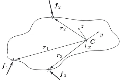
Figure 1: Object interaction with three interaction points.
active (corresponding to controllable system modifications) and passive CFs (corresponding to uncontrollable system modifications) using the manipulation stiffness and manip-ulator Jacobian. Then, the IFs can be determined using IF synthesis maximizing for example grasp robustness. An approach for IF analysis, which allows subspace dimen-sion calculation of controllable and uncontrollable parts of the CFs and MFs was developed by Zhang and Gruver [12]. They classified grasps into three categories: power grasps, constrained motion grasps and free motion grasps [13]. While the approach of Williams and Khatib [10] incorpo-rates virtual forces, i.e. physically impossible forces, meth-ods not generating virtual forces have been presented by Zhang et al. [12,13] and by Yoshikawa and Nagai [9]. How-ever, the approach of Zhang et al. allows no calculation of CFs and MFs directly, but of the dimensions of the control-lable and uncontrolcontrol-lable parts only. Furthermore, the ap-proach of Yoshikawa and Nagai can only be applied to two, three and four finger grasps and it is not known if a solution for more than four fingers exists.
In this paper we present a new decomposition approach for IF analysis, which is suitable for all numbers of contact points and results in physically possible forces only.
2
I
NTERACTION
F
ORCE
D
ECOMPO
-SITION
2.1
Problem Formulation
We consider a rigid object and point contacts, which means that only interaction forces, but not torques can be applied on the object. For clarification Fig. 1 shows an object with an object-fixed coordinate system C, vectors ri pointing
from the origin of the coordinate system to the respective contact points and interaction forcesfi. The effect of an IF
ion the object can be twofold and thus, can be decomposed as follows:
fi=fc,i+fm,i. (1)
If wrenches resulting from the IFs exist, which compen-sate each other, the object is squeezed, stretched or distorted and an internal wrench describing the mechanical stress in-side the object, also called internal forces [14], evolves. We call components of the IFs with this property compensating forces (CFs) and refer to them withfc,ithroughout this
pa-per. If wrenches resulting from an IF are not compensated, they accelerate the object and an external wrench describ-ing the motion of the object, also called external forces [14], evolves. We call components of the IFs with this property manipulating forces (MFs) and refer to them withfm,i. The MFs generate a resulting wrenchwracting on the
ob-ject with
wr=
fr
τr
=
N
X
i=1
fi
ri×fi
| {z }
wi
=
N
X
i=1
wi=W f
=
N
X
i=1
fm,i
ri×fm,i
| {z }
wm,i
=
N
X
i=1
wm,i=W fm
(2)
where fr is the accelerating force, τr the accelerating
torque and
W =
I I · · · I R1 R2 · · · RN
, fm=[fTm,1,f
T m,2· · ·f
T m,N]T,
f =[fT1,fT2 · · ·fTN]T,
wi=
fi
ri×fi
and wm,i=
fm,i
ri×fm,i
,
wherebyIis the identity matrix andRithe skew symmetric
matrix operator ofriperforming the cross product.
CFs, on the other hand, generate internal wrencheswc,iand
following their definition they sum up to zero. It follows
N
X
i=1
fc,i
ri×fc,i
=
N
X
i=1
wc,i=W fc=0 (3)
with
fc= [fTc,1,f
T c,2· · ·f
T
c,N]T and
wc,i=
fc,i
ri×fc,i
.
Using (1), (2) and (3) an under-determined system of equa-tions is defined.
2.2
Related Work
f1 f2
Figure 2: Two finger grasp example without gravity. (cp. [9])
will have a more detailed look at two representative solu-tions, the virtual linkage model of Williams and Khatib [10] and the more intuitively derived approach of Yoshikawa and Nagai [15].
For a better comprehension of the virtual linkage model the example shown in Fig. 2 will be used with
fm,1=f1, fc,1=0, and fm,2=0, fc,2=0.
The general solution of the virtual linkage model for the resulting MFs is
fm=WT(W WT)−1W f (4)
which reduces to
fm,i = 1
Nfr+Ri
N
X
j=1
R2j
−1
τr if N
X
i=1
ri=0.
(5) It can be shown that the solution to (4) is invariant to shifts of the object-fixed coordinate system and thus, after shift-ing the reference frame toPiri= 0, (5) can be considered
a simplified solution of (4). From (5) it can be seen that the resulting force fr on the object is distributed equally
on all MFs. That means even if an IF has no influence on the acceleration of the object it is assigned a MF larger than zero. We call these forces virtual forces because they are physically impossible and therefore non-existent. For the example in Fig. 2 this meansfm,2=f1/26=0.
The approach of Yoshikawa and Nagai in contrary does not lead to virtual forces, but has other drawbacks. Their method is based on three intuitive assumptions: First, CFs should always be inside the friction cone. Second, a MF should have no part pointing into the inverse direction of the corresponding CF. Third, a MF has no part resulting in com-pression or tension of the object, neglecting torsion. From these assumptions follow two steps for IF decomposition. In the first step, possible grasp modesα = [α1,· · ·, αm]
withαi ∈ {−1; 1}have to be chosen. A grasp mode
de-scribes if CFs between two interaction points squeeze or stretch the object and depend on the surface normals and the friction coefficients at the interaction points. A grasp mode can be calculated for the three finger grasp by using the algorithm described in [9]. The CFs are described in a subspacehcusing these grasp modes. In this subspace a
so-lution is only feasible if all values are positive. Otherwise, the grasp mode would define compression, while the sub-space value would result in tension.
In the second step, given a grasp mode, different solutions to the MFs, again described in an own subspace hm, are
tested for feasibility, i.e. no MF results into tension or com-pression of the object neglecting torsion and no MF points into the inverse direction of its corresponding CF. The dif-ferent solutions result from any perturbation of a selection vectork= [k1,· · ·, kl]withki ∈ {0; 1}that selects
possi-ble directions for the MFs.
From the above considerations the following system of equations results:
wr=W f =W Bh ⇒ h=B−1f
withB=Bc(α,r1,· · ·,rn) Bm(k,α,r1,· · ·,rn),
h=
hc
hm
.
After calculating all solutions for the MFs from the pertur-bations ofk, the feasible solution, if one exists, has to be found by testing if the subspace values fulfill the assump-tions. Using the resultinghthe CFs and MFs can be calcu-lated by
fc =Bchc, fm=Bmhm.
This approach has multiple drawbacks. For example it is possible that multiple grasp modes (see [9] for examples) and eventually multiple solutions exist or that no grasp mode exists. There may be also no selection vector which leads to a feasible solution and thus, decomposition. This is due to the constraint requiring that a MF is composed of forces which do not lead to tension or compression for se-lected parts of the corresponding CF (cp. Condition 3 for MFs in [9]) which also reduces the solution space to the empty set for most grasp configurations with four fingers. Furthermore, only algorithms are given to determine the grasp mode for two and three finger grasps, because the ap-proach gets very complex when additional interaction points are added. It remains also unclear if a solution for more than four fingers exists.
2.3
Proposed IF Decomposition
So far the mathematical decomposition into MFs and CFs is based on the definitions given in Section 2.1. We will extend these definitions to allow physically possible forces only. For this reason we introduce the following bounding constraint.
Bounding constraint: This constraint is inherently
fi
2
|fi|
[image:4.595.120.233.96.208.2]2
Figure 3: The visualized solution space given by (6). Every vector combination consists offm,iandfc,i.
from its corresponding IF. This is stated in Lemma 1 (see Sec. 5 for proof).
Lemma 1. Considering that a MF is the part of its IF, which performs physical work and taking (1) into account it fol-lows
fTm,ifm,i+fTc,ifc,i≤fTifi. (6) Remark: The inequality constraint (6) bounds the solution
space for the CFs and the MFs to a sphere around their re-spective IFs with radius|fi|/2 as illustrated in Fig. 3 for two dimensions.
Given the bounding constraint the solution space is reduced to physically possible forces, but still an infinite number of solutions exist. A first intuitive approach to solve this problem would be to define that MFs contribute only to the acceleration of an object without any compensating parts, which would lead to a full decomposition. However, torques applied on the object at the single interaction points can only be orthogonal to the corresponding vectorri(cp. (2)).
Furthermore, considering that the resulting torque mostly points into a direction, which is not orthogonal to any of the
ri, , it is likely that for the specific studied situation no
so-lutions for the full decomposition problem exists. From this follows Lemma 2 (see Sec. 5 for proof).
Lemma 2. Full decomposition of IFs into CFs leading to wrenches compensating each other and MFs contributing to the resulting wrench only, i.e. without compensating parts, is in general not possible.
Therefore, we adopt an intuitive approach for the two finger grasp originally formulated by Yoshikawa and Na-gai [9], and extend it to more than two fingers. Yoshikawa and Nagai propose to calculate the internal forces for a two finger grasp based on
fc,1/2=±min (|fT1e12|,| −fT2e12|)e12 with (7)
e12=
r2−r1
||r2−r1||
, (8)
where e12 represents the unit vector from one interaction
point to the other one. It should be noted that (7) holds also
for objects with holes. In (7) the interaction forces are pro-jected on the line connecting the interaction points and the smaller projected force is chosen as compensating compo-nent. This is due to the fact that both CFs have to compen-sate each other, which means that their norms have to be equal and thus, only the smaller norm can be fully compen-sated. In other words, the CFs are maximized which is the first property we abstract from this approach. Extending this idea to multiple fingers we propose to design a cost function that maximizes the CFs. Mathematically, the cost function can be established in multiple ways, e.g. by minimizing the MFs, which are not contributing to the resulting wrench or by maximizing the CFs. Following up on this idea, the so-lution space of the CFs has to be bounded so that they do not increase to infinity. In the approach by Yoshikawa and Nagai this is achieved by the proposition that a MF should have no part pointing into the inverse direction of the corre-sponding CF and vice versa, i.e.fTc,ifm,i ≥0. Utilizing (1)
we can derive the previously motivated bounding constraint (6) and get a second property. A last property is given by the fact that CFs can only be applied along the line connecting the two interaction points, which is the only solution to (3) for the two finger grasp [16]. Hence, using (3) additionally to the bounding constraint allows us to expand the approach of Yoshikawa and Nagai to more than two fingers.
IF Decomposition Theorem (IFDT). For a precision grasp the IF decomposition problem is given by the follow-ing optimization problem:
arg max fc,i
J =|fc|2 (9)
s.t. W fc=0, (10)
fTc,ifc,i≤fTifc,i ∀i. (11)
Please note that inequality (11) is obtained by inserting (1) into (6).
Remark: It can be shown that the solution for the
two-finger grasp equals the solution proposed by Yoshikawa and Nagai as shown in Lemma 3 (see Sec. 5).
3
N
UMERICAL
E
XAMPLES
For illustration and comparison of the new decomposition approach with state-of-the-art approaches, namely the ap-proach of Yoshikawa and Nagai [9] and the virtual linkage model [10], the example of Fig. 4 is adopted with
f1=
1 2T, r1=
0 −2T, f2=
−ε −1T, r2=
√
3 1T, f3=ε −1T, r3=−√3 1
T
,
f1
r2
r1
f2
r3
f3
[image:5.595.102.253.93.214.2]x y
Figure 4: A three finger grasp.
(5) can be used directly. The decomposition based on the newly proposed IFDT was performed using the optimiza-tion toolbox of MATLAB adopting an interior-point algo-rithm, which is suitable for quadratic optimization problems with nonlinear equality and inequality constraints.
Assumingε = 0,f2andf3are compensated byf1and the only force influencing the objects motion is the x com-ponent off1. The MFs and CFs of the virtual linkage model
(vl) can be determined using (5) and (1) and are given by:
vlf m,1≈
0.67 0T, vlfc,1≈0.33 2T,
vlf m,2≈
0.17 0.29T, vlf c,2≈
−0.17 −1.29T,
vl
fm,3≈
0.17 −0.29T, vlfc,3≈
−0.17 −0.71T.
From this follows that
vlfT
m,2vlfm,2+vlf
T
c,2vlfc,2>f
T
2f2,
which is contradicting (6) and, thus, for fm,2,vl virtual
forces are calculated. Alsofm,3,vl would contain virtual
forces if the influence off1 on the object’s motion gets
larger. Summarizing, for the virtual linkage model we can conclude that if the object is accelerated mostly by a spe-cific IF and the accelerating forces (MFs) are much larger than the stabilizing forces (CFs), the decomposed MFs will primarily be virtual.
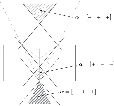
Using the approach of Yoshikawa and Nagai the grasp modes shown in Fig. 5 result. However, for ε ∈
[0.356; 0.577]there exists no solution because the constraint prohibiting the MFs to lead to tension or compression along a joining line cannot be fulfilled. Thus, depending on the possible grasp modes there may always be regions where no decomposition is possible. In contrast to these approaches the IFDT leads to the following MFs and CFs, which are respecting the bounding constraint:
IF DT
fm,1=
1 0T, IF DTfc,1=
0 2T,
IF DT
fm,2=
0 0T, IF DTfc,2=
0 −1T,
IF DTf m,3=
0 0T, IF DTfc,3=0 −1T.
x y
α=− + +
α=− + +
α=+ + +
Figure 5: Possible grasp modes for the example shown in Fig. 4 using the friction constantµ = 0.9. α= [− + +]
means that the CF between the interaction pointsr2andr3
is stretching.α= [+ + +]means that all CF are squeezing.
4
C
ONCLUSION
We have introduced a new approach for the decomposition of IFs into MFs and CFs for IF analysis. For this purpose an intuitive approach originally introduced by Yoshikawa and Nagai for the two finger grasp has been formalized and ex-tended to more than two interaction points resulting in an optimization problem, which maximizes CFs. This maxi-mization is only possible due to a new introduced bounding constraint, which bounds the solution space of the MFs and the CFs. The constraint is motivated by considering that a force component cannot do more physical work than the original interaction force.
Existing decomposition approaches, the virtual linkage model and the approach of Yoshikawa and Nagai, were compared to the newly proposed IF decomposition. While the virtual linkage model was found to lead to impossible MFs, when taking into account the law of conservation of energy for each interaction force separately, the main draw-back of the method of Yoshikawa and Nagai was found that it is not clear if there exists a solution for more than four interaction points.
Since the optimization problem contains a quadratic con-straint which complicates an analytical solution, our future work will target a numerical solution for online decomposi-tion of IFs.
5
A
PPENDIX
Lemma 1. Considering that a MF is the part of its IF which performs physical work and taking (1) into account it fol-lows
[image:5.595.361.543.99.268.2]Proof. Because a MF is the part of its IF contributing to the
accelerating wrench acting on the object two properties can be formulated: First, the projection of the IF on its corre-sponding MF
fi,proj=
fTi
fm,i
|fm,i|
f
m,i
|fm,i| (13)
can be used to describe an upper bound for the physical work performed by the MF. Second, if the work performed by the IF is positive/negative also the work done by the corresponding MF must be positive/negative. From these statements the following two inequalities can be formu-lated which must hold for every infinitesimal line segment dr=rdswith|r|= 1
0(≤>)fTm,irds(≤>)fTi,projrds (14) or rotary segment dφ=qdϕwith|q|= 1
0(≤>)ri×fm,i
T
qdϕ(≤>)ri×fi,proj
T
qdϕ. (15) Substituting (13) into (14) and (15) yields
0(≤>)fTm,irds
(>)
≤ cifTm,irds,
0
(>)
≤ ri×fm,i
T
qdϕ
(>)
≤ ciri×fm,i
T
qdϕ
with
ci=fTi
fm,i |fm,i|2
.
Comparing the coefficients it follows
0≤1≤ci. (16)
Substitutingciinto (16) leads to
0≤fTm,ifm,i=|fm,i|2≤fTifm,i. (17) Since fTi fm,i ≥ 0 the angle αbetweenfi and fm,i is
within[−π/2;π/2]. When substituting (1) into (17) follows
fTifc,i≥ |fc,i|2=fTc,ifc,i (18)
Adding (17) and (18) results in inequality (12).
Lemma 2. Full decomposition of IFs into CFs leading to wrenches compensating each other and MFs contributing to the resulting wrench only, i.e. without compensating parts, is in general not possible.
Proof. If a force is not pointing into the direction of fr
nor its resulting torque into the direction of τr, then this
force must have components, which are compensated by other forces. Consequently, full decomposition can only
be achieved if the MFs consist of two parts only: one part pointing into the direction offrand a second part denoted
asfx,ileading to a torque pointing into the direction ofτr.
From this follows:
fm,i=d1fr+fx,i d1∈R+0, (19)
ri×fx,i=d2τr d2∈R+0. (20)
In (20) the torque on the left side is orthogonal tori, while
the torque on the right side is pointing into the direction of
τr. Thus, a solution to (20) exists only ifτris orthogonal
tori. As it is, however, easy to find an example with a
force and grasping point constellation comprising a torque
τrthat is not orthogonal tori, it can be concluded that in
general the MFs cannot have only parts contributing to the resulting wrench, but will also contain compensating forces and torques.
Lemma 3. The solution to the two-finger grasp obtained with the newly proposed IFDT equals the intuitive solution
(7) derived by Yoshikawa and Nagai [15].
Proof. For the two-finger grasp constraint (10) can be
writ-ten as follows
I I
R1 R2
fc,1
fc,2
=0. (21)
From the first row follows that the two CFs have equal norms and point in opposite directionsfc,2 = −fc,1.
In-serting this result into the second row of (21) and rewriting the cross product in its original form gives
(r1−r2)×fc,1=0.
with the trivial solutionfc,1 =fc,2 =0orfc,1andfc,2
parallel tor1−r2. The non-trivial solution means that both
CFs lie on the line connecting the two interaction points, which can be parametrized usinge12from (8):
fc,1=αe12, fc,2=−αe12 α∈R (22)
Thus, the valueαremains to be determined. Using (22) the optimization problem (9)-(11) can be reformulated to
arg max
α J = 2α
2 (23)
s.t. α2≤αfT1e12, (24)
α2≤ −αfT
2e12. (25)
Assume thatfT1e12 >0andfT2e12 <0and note that the
left sides of (24) and (25) are always positive or zero. Then, ifα∈R−0, (24) and (25) allow the solutionα= 0only. On
the other hand, ifα∈R+0 the cost function can take larger
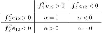
Table 1: Possible sets ofαfor given projections of the IFs on the line connecting the interaction points.
fT1e12>0 fT1e12<0
fT2e12>0 α= 0 α <0
fT2e12<0 α >0 α= 0
fT1e12andfT2e12 summarized in Table 1. Hence,
depen-dent on the IFs and the line connecting the interaction points one out of four possible solutions exist for maximization of (23) under the constraints (24) and (25). Two of them re-quireα= 0. The other two can be determined by reformu-lating (24) and (25) as follows
ifα >0⇒
(
α≤fT1e12=k1
α≤ −fT2e12=k2
(26)
ifα <0⇒
(
α≥fT1e12=−k1
α≥ −fT2e12=−k2
(27)
withk1, k2 ∈ R+0. If f
T
1e12 > 0 and fT2e12 < 0, α
is positive and must be maximized under constraint (26). Thus,αequals eitherk1 ork2. Second, iffT1e12<0and
fT2e12 > 0, αis negative and must be minimized under
constraint (27). Thus,αequals either−k1 or−k2.
Com-bining these results we can state that
α=±min(|fT1e12|,| −fT2e12|). (28)
Thus, by inserting (28) into (22) we get (7).
References
[1] D. Prattichizzo, M. Malvezzi, M. Aggravi, and T. Wimbock, “Object motion-decoupled internal force control for a compliant multifingered hand,” in IEEE
International Conference on Robotics and Automa-tion, May 2012, pp. 1508–1513.
[2] M. Buss, H. Hashimoto, and J. Moore, “Dextrous hand grasping force optimization,” IEEE Transactions on
Robotics and Automation, vol. 12, no. 3, pp. 406–418,
1996.
[3] T. Yoshikawa and X. Zheng, “Coordinated dynamic hybrid position/force control for multiple robot manip-ulators handling one constrained object,” in IEEE
In-ternational Conference on Robotics and Automation,
vol. 2, May 1990, pp. 1178–1183.
[4] D. Sun and J. Mills, “Manipulating rigid pay-loads with multiple robots using compliant grippers,”
IEEE/ASME Transactions on Mechatronics, vol. 7,
no. 1, pp. 23–34, Mar 2002.
[5] M. A. Smith and J. F. Soechting, “Modulation of grasping forces during object transport.” Journal of
Neurophysiology, vol. 93, no. 1, pp. 137–145, 2005.
[6] G. Slota, M. Latash, and V. Zatsiorsky, “Grip forces during object manipulation: experiment, mathemat-ical model, and validation,” Experimental Brain
Re-search, vol. 213, pp. 125–139, 2011.
[7] A. M. Schmidts, D. Lee, and A. Peer, “Imitation learn-ing of human grasplearn-ing skills from motion and force data,” in IEEE/RSJ International Conference on
Intel-ligent Robots and Systems, 2011.
[8] M. Aicardi, G. Casalino, and G. Cannata, “Contact force canonical decomposition and the role of inter-nal forces in robust grasp planning problems,”
Inter-national Journal on Robotic Research, vol. 15, no. 4,
pp. 351–364, Aug 1996.
[9] T. Yoshikawa and K. Nagai, “Manipulating and grasp-ing forces in manipulation by multifgrasp-ingered robot hands,” IEEE Transactions on Robotics and
Automa-tion, vol. 7, no. 1, pp. 67 –77, Feb 1991.
[10] D. Williams and O. Khatib, “The virtual linkage: a model for internal forces in multi-grasp manipula-tion,” in IEEE International Conference on Robotics
and Automation, vol. 1, May 1993, pp. 1025 –1030.
[11] A. Bicchi, “Force distribution in multiple whole-limb manipulation,” in IEEE International Conference on
Robotics and Automation, vol. 2, 1993, pp. 196–201.
[12] Y. Zhang and W. Gruver, “Definition and force distri-bution of power grasps,” in IEEE International
Con-ference on Robotics and Automation, vol. 2, 1995, pp.
1373–1378.
[13] Y. Zhang, W. Gruver, J. Li, and Q. Zhang, “Classifi-cation of grasps by robot hands,” IEEE Transactions
on Systems, Man, and Cybernetics, vol. 31, no. 3, pp.
436–444, 2001.
[14] B. Siciliano and O. Khatib, Eds., Springer Handbook
of Robotics. Springer, 2008.
[15] T. Yoshikawa, “Virtual truss model for characteri-zation of internal forces for multiple finger grasps,”
IEEE Transactions on Robotics and Automation,
vol. 15, no. 5, pp. 941 –947, Oct 1999.
[16] V. Kumar and K. Waldron, “Force distribution in closed kinematic chains,” in IEEE International
Con-ference on Robotics and Automation, vol. 1, 1988, pp.
![Figure 2: Two finger grasp example without gravity. (cp.[9])](https://thumb-us.123doks.com/thumbv2/123dok_us/640591.565287/3.595.311.545.226.281/figure-nger-grasp-example-gravity-cp.webp)