For Peer Review
The effects of composite laminate stiffness and loading on stress resultant concentration factor around a hole
Journal: Part C: Journal of Mechanical Engineering Science
Manuscript ID JMES-17-1220.R1 Manuscript Type: Original article Date Submitted by the Author: 11-Dec-2017
Complete List of Authors: damghani, mahdi; Engineering Design and Mathematics Harrison, Christopher; Atkins Bristol
Kennedy, David; Cardiff University
Keywords: Conformal mapping, Complex variable approach, Stress resultant concentration, Hole, Carbon Fibre Reinforced Polymer
Abstract:
For Peer Review
The effects of composite laminate stiffness and loading on
stress resultant concentration factor around a hole
M Damghani*a, C Harrisonb, and D Kennedyc
a
Engineering Modelling and Simulation Group (EMSG), Engineering Design and
Mathematics Department, University of the West of England (UWE), Bristol, UK
b Advanced Engineering Unit, Atkins global, Bristol, UK
c
Engineering Department, Cardiff University, Cardiff, UK
Abstract
An analytical tool is developed using conformal mapping and the complex variable
method for determining the Stress Resultant Concentration Factor (SRCF) in an infinite
plate with a circular or elliptical hole. This tool is validated against Finite Element
Analysis (FEA). A population space of 305 laminates is generated by stacking
uni-directional Carbon Fibre Reinforced Polymer (CFRP) material at various orientations
covering a wide spectrum of homogenised stiffness values. The analytical approach is
then used to study the effect(s) of loading conditions, stacking sequences and laminate
homogenised stiffness values on the SRCF at the edge of a circular hole.
Keywords: Conformal mapping, Complex variable approach, Stress resultant
concentration, Carbon Fibre Reinforced Polymer, Hole
*
Corresponding author: Engineering Modelling and Simulation Group (EMSG), Engineering Design and
Mathematics Department, University of the West of England (UWE), Bristol, UK
Email:Mahdi.Damghani@uwe.ac.uk 3
For Peer Review
1 IntroductionComposite materials are widely used in the aerospace industry for high performance
components. For instance, more than 50% of Airbus A350 and Boeing 787 passenger
aircraft are made of such materials. Composites are also finding applications as load
bearing structural components in other industries amongst which are defence,
automotive, marine, oil and gas, rail and civil engineering. Due to the high stiffness to
weight ratio of such materials compared to conventional metallic materials such as
aluminium, the use of composites can lead to significant weight saving which in turn
brings about improved performance and reduction in fuel consumption. In order to use
the full potential of such materials, it is essential to better understand and characterise
their behaviour.
As the result of design requirements and practicality of use, the existence of holes is
inevitable in composite structures such as windows in the aircraft fuselage,
access-holes in the wing, drilled access-holes for bolted and riveted connections etc. It is well known
that elevated stresses give rise to stress/strain concentrations occurring at the vicinity
of holes making them prone to crack initiation and propagation. The quantity of such
stresses is dependent on the geometry of a hole, loading conditions, stiffness and
anisotropy of the composite laminate.
There have been numerous attempts in obtaining Stress Concentration Factor (SCF) at
the boundary of a hole/notch in laminated composite plates. Some of such works make
use of numerical approaches such as Finite Element Analysis (FEA) 1–5 whilst others
focus on the use of fast and precise analytical methods 6–15. Experimental techniques
compliment the two previous approaches and have been used extensively to validate
both analytical and numerical solutions.
The majority of the analytical works in the literature focus on the methods of
determination of stress state around a hole and are based on the work of Muskhelishvili
15
and Savin 16. For example, Bonora et al. 6,7 provided closed form solutions for stress 3
For Peer Review
state around circular and elliptical holes in laminated composite plates using the classic
Airy solution method. Amongst similar works are the works of Chauhan et al. 10. They
employed an analytical complex variable method and studied the effect of stacking
sequence on tangential stresses around a rectangular hole under uni-axial loading for a
finite Graphite/Epoxy composite plate. For their laminate of study, they concluded that
maximum and minimum SCF take place for [08]s and [908]s lay-up, respectively.
Sharma 17 studied the effect of fibre orientation, for both Graphite/Epoxy and
Carbon/Epoxy composite laminates, under uni-axial loading on stress pattern at the
edge of a polygonal hole. He concluded that minimum and maximum SCF around the
hole occurs for 90o and 0o fibre angles, respectively. Russo et al. 13 performed a
parametric study of SCF in both Glass Fibre Reinforced Polymer (GFRP) and Carbon
Fibre Reinforced Polymer (CFRP) containing a circular hole both analytically and
experimentally. Hufenbach et al. 14 used a complex variable method and mapping
functions to obtain stress fields around circular and elliptical holes in a finite
Glass-Fibre-Polypropylene (GF/PP) composite plate. Excellent agreement was established
between the proposed analytical method and experimental results. Although SCF
around circular/elliptical holes represents the case in most engineering applications,
but some researchers investigated SCF around holes of various other shapes such as
triangular 18,19, rectangular 11, hypocycloidal 10, polygonal17,20 and irregular21,22 holes.
The use of closed form analytical solutions to determine SCF in geometrically complex
structures and general loading scenarios is very difficult and hence the FEA is often
adopted. For instance, Jain et al. 23 employed FEA and studied the effect of hole
diameter to plate width of rectangular isotropic, orthotropic and laminated composite
plates with central circular hole under different transverse static loading conditions.
Khechai et al. 24 evaluated the stress distribution around circular holes in thin isotropic
and symmetric laminated plates, subjected to uniaxial loading by using a specially
formulated quadrilateral finite element. Othman et al. 25 used FEA and the concept of 3
For Peer Review
Defence Hole System (DHS) to reduce stress concentration in holes of composite
bolted joints. Darwish et al. 26,27 used three dimensional FEA to formulate stress
concentration around circular countersunk holes in composite orthotropic plates under
uniaxial loading.
Experimental techniques have been used to obtain SCF in plates having circular holes.
Makki et al. 1 performed uniaxial testing of both steel plates and orthotropic CFRP
laminates and measured stress concentration factor for circular holes of various
dimensions using Digital Image Correlation (DIC) technique. The result given by the
DIC camera was identical with the FEA results for isotropic materials. On the contrary,
for orthotropic materials, the results of the DIC method were not coherent with the FEA
and the literature values, which reflected on the anisotropic character of the composite
material. DIC technique was used by Zhao et al. 28 to evaluate stress field around
circular hole in thermoplastic orthotropic composite plates. They observed good
correlation of numerical results with those of experimental procedure.
Despite considerable amount of attention in developing analytical, numerical and
experimental methods, a comprehensive parametric study on a large number of
laminated composite structures demonstrating the effects of stiffness of structure and
the loading condition on the Stress Resultant Concentration Factor (SRCF) has
received little attention with scarce amount of scientific data in the subject area. To
achieve such an objective, the use of fast and computationally efficient methods has
clear advantage over labour intensive and computationally expensive numerical and
FEA.
Therefore, in the present paper, the authors address such shortcomings and lack of
data via the use of analytical approach. The approach employs the well-established
complex variable method for anisotropic material and is utilised to obtain stress
resultant distribution and Stress Resultant Concentration Factor (SRCF) at the edge of
an elliptical or circular hole in an infinite composite plate under membrane loading, 3
For Peer Review
which is the dominant loading and boundary condition for thin structures (see Section 2
for a brief review of the theory and the expressions for the stress components for any
combination of membrane loading). The analytical formulation is embedded in Excel
software 29 with a Visual Basic macro and validated by FEA using MSC Nastran 2014
30
(see Section 3 for details of validation). The approved analytical solution is used for a
parametric study of the influence of composite laminate stiffness on SRCF around a
circular hole for several loading conditions on 305 composite laminates. The results of
the parametric study are presented in Section 4.
2 Methodology
In this study, conformal mapping, i.e. mapping that preserves angles, and the complex
variable approach is used to determine stresses at the edge of a circular or elliptical
hole in an infinite composite plate subject to remote membrane forces. It is assumed
that the plate is in a plane stress state and body forces are absent. It is further
assumed that the plate material remains in its linear elastic state. The effects of out of
plane loading are not considered in the current study.
The stress-strain relationship in a composite material is defined as 6,7,17,31:
=
κ ε0
D B
B A M
N (1)
where
[ ]
A ,[ ]
B and[ ]
D are extensional, extensional-bending coupling and bendingstiffness matrices, respectively.
{ }
ε
0 and{ }
κ are strain and curvature matrices at the mid-plane of the composite laminate, respectively.{ }
N and{ }
M are 3x1 matrices of membrane and out of plane bending loading, also known as stress resultants, withunits of force per unit width and moment per unit width, respectively. Stress resultants
are defined as: 3
For Peer Review
∫
∫
∫
− − −=
=
=
2 2 2 2 2 2,
,
h h xy xy h h y y h h xx
dz
N
dz
N
dx
N
σ
σ
τ
(2)where
σ
x,σ
y andτ
xy are direct normal and shear stresses through the laminatethickness. In order to obtain the compliance matrix of a composite material, the ABD
matrix in the above equation is inverted, yielding:
= M N d b b a κ ε0 (3)
where the
abd
matrix is the compliance matrix with the following elements:[ ] [ ] [ ] [ ][ ] [ ][ ] [ ]
(
)
[ ][ ]
[ ] [ ] [ ][ ] [ ][ ] [ ]
(
)
[ ] [ ] [ ][ ] [ ]
(
1)
11 1 1 1 1 1 1 1 − − − − − − − − − −
−
=
−
−
=
−
+
=
B
A
B
D
d
B
A
B
D
B
A
b
A
B
B
A
B
D
B
A
A
a
(4)For simplicity, the composite laminate is assumed to be symmetric. Therefore, the
membrane-bending coupling terms vanish, i.e.
[ ]
b
=
0
, and composite laminatemid-plane strains can be expressed as:
xy y x xy xy y x y xy y x x N a N a N a N a N a N a N a N a N a 66 26 16 26 22 12 16 12 11 + + = + + = + + =
γ
ε
ε
(5)where aij(i,j=1,2,6) coefficients are elements in the compliance matrix.
In the absence of body forces, stress resultants can be defined using Airy’s stress
function U(x,y) as follows:
y
x
U
t
N
x
U
t
N
y
U
t
N
x y xy∂
∂
∂
−
=
∂
∂
=
∂
∂
=
2 2 2 2 2,
,
(6)where t is the thickness of the composite laminate. It is worth noting that in the
For Peer Review
instead of composite ply level stresses. This is due to the use of Airy stress functions
that are suitable for two dimensional plane stress/plane strain problems, where stress
is assumed to be constant through the thickness. However, for composite laminate
structures, the stress through the thickness is not constant and has discontinuous
distribution. The use of stress resultant overcomes such limitation. Stress resultants
are crucial for quantifying static and fatigue strength of composite structures. For
instance, in static analysis they can be used to predict the notched strength of
composite laminates containing circular holes and straight cracks based on either the
‘‘point stress’’ criterion or the ‘‘average stress’’ criterion. The reader is referred to
Pandita et al. 32 for further details.
We also know that (from the compatibility of strains in a two dimensional space):
y x x y xy y x ∂ ∂ ∂ = ∂ ∂ + ∂
∂ ε ε 2γ
2 2
2 2
(7)
Combining the above equations leads to:
0
2
)
2
(
2
4 4 11 3 4 16 2 2 4 66 12 3 4 26 4 4 22=
∂
∂
+
∂
∂
∂
−
∂
∂
∂
+
+
∂
∂
∂
−
∂
∂
y
U
a
y
x
U
a
y
x
U
a
a
y
x
U
a
x
U
a
(8)Lekhnitskii 33 demonstrated that to solve two-dimensional anisotropic problems, it is
essential to solve the following characteristic equation:
(
2)
2 02 2 26 22
66 12 3 16 4
11S − a S + a +a S − a S+a =
a (9)
The roots of the characteristic equation, also known as complex values of anisotropy,
have complex values and are in conjugate pairs as:
2 4 2 2 2 1 3 1 1 1
;
;
s
s
i
s
s
s
i
s
=
+
=
=
+
=
β
α
β
α
(10)Airy’s stress function can be represented by arbitrary functions of Xk of variables zk
For Peer Review
y
i
y
x
y
s
x
z
y
i
y
x
y
s
x
z
z
X
z
X
z
X
z
X
y
x
U
2 2 2 2 1 1 1 1 2 2 1 1 2 2 11
(
)
(
)
(
)
(
)
)
,
(
β
α
β
α
+
+
=
+
=
+
+
=
+
=
+
+
+
=
(11)and defining φ(z1) and ψ(z2) as:
)
(
1 1 1z
dz
dX
φ
=
,(
2)
2
2
z
dz
dX
ψ
=
,(
1)
1 1
z
dz
X
d
φ
=
,(
2)
2 2
z
dz
X
d
ψ
=
(12)) (z1
φ and ψ(z2) are analytic functions which suggests that they have continuous
partial derivatives within their domain. Stress resultant components in terms of φ(z1)
and ψ(z2), can be calculated as:
[
]
[
]
[
( ) ( )]
Re 2 ) ( ) ( Re 2 ) ( ) ( Re 2 2 ' 0 2 1 ' 0 1 2 ' 0 1 ' 0 2 ' 0 2 2 1 ' 0 2 1 z s z s N z z N z s z s N xy y x ψ φ ψ φ ψ φ + − = + = + = (13)For the sake of conciseness, the reader is referred to Appendix A for details of
obtaining mapping, analytic and stress functions.
2.1 Material and lay-up
In order to study the effects of SRCF on various composite laminates with a range of
stiffness values, a uni-directional composite ply with mechanical properties given in
Table 1 is used.
Three hundred and five balanced and symmetric stacking sequences are generated, by
assuming a laminate with 28 plies, to cover a wide spectrum of composite laminates
with various homogenised stiffness values, i.e. shear modulus and modulus in
x
andy directions. The population of stacking sequences had a homogenised shear
modulus ranging from 5.58GPa to 27.51GPa and direct modulus ranging from 10GPa
For Peer Review
3 Validation of the analytical method with FEAMSC Nastran was used to perform FEA. The plate is modelled using the boundary
conditions and loading represented in Fig. 1. Fx and Fy point forces are distributed to
the plate structure using RBE3 elements. RBE3 elements are interpolation constraint
elements that define the motion at a reference grid point, i.e. hole centre, as the
weighted average of the motions at a set of other grid points, i.e. hole edge. The
structure is constrained (grounded) at the middle of the hole. Since the master node of
RBE3 elements at the location of the hole cannot be grounded, this node is connected
to a very rigid spring element (CBUSH element) of zero length. The other end of
CBUSH element is then constrained in all degrees of freedom.
The validation is performed for material, composite lay-up, hole geometry, and loading
type given in Table 2. Hereafter, Parameter
λ
is defined as the ratio of loading in ydirection to that of
x
direction (λ
=Ny/Nx). In all validation runs, values of appliedloads are Nx =280N/mm (
λ
=
0
), Nx =Ny =280N/mm (λ
=
1
), for uni-axial andbi-axial loading conditions, respectively.
The contour plot of output stresses, i.e. average normal stresses in
x
and y directionand average shear stress in xy plane, at the edge of circular hole for bi-axial loading
(see Val-A in Table 2) and uni-axial loading (see Val-B in Table 2) is given in Fig. 2 and
Fig. 3, respectively. Comparison of analytical method with the numerical approach is
given in Fig. 4 and Fig. 5. These figures illustrate excellent agreement of FE results
with those of analytical approach.
4 Results and discussions
The objective of this study is to investigate the effect(s) of composite laminate stiffness,
resulting from different stacking sequences, and loading conditions on the quantity of
SRCF at the edge of a hole. The SRCF is important in the design of composite 3
For Peer Review
structures when quantifying static or fatigue strength. A circular hole with radius of
10mm is considered hereafter, representative of a bolt or rivet hole in a typical
aerospace structure.
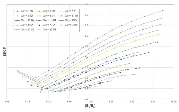
Fig. 6 shows SRCF for various quantities of Ex/Ey (homogenised stiffness values of
composite laminate in
x
and y directions) under uni-axial loading. The SRCF in thiscontext is defined as the ratio of maximum tangential stress resultant (N/mm) at the
edge of the hole to the remote applied stress resultant, i.e. 2 2 y x N
N N
SRCF = θ + . It
should be noted, for interpretation of the results, SRCF values represent average
stress concentration times the thickness of homogenised section rather than ply level
stresses.
It is evident from the graph that for all homogenised shear modulus values of the
laminate, the SRCF decreases with the decrease in the ratio of Ex/Ey. In other words,
reducing the stiffness in the direction of applied load brings about less stress resultant
concentration around the edge of the hole. The graph also suggests, for uni-axial
loading, introduction of angle plies in the stacking sequence leads to an increase in
homogenised shear modulus bringing about the reduction of SRCF. One noticeable
observation is the increase of SRCF for some shear moduli in the interval Ex/Ey<0.3.
This is mainly due to the use of stacking sequences with a dominant number of plies in
90o angle and no plies at 0o angle (0o plies have fibres parallel to loading direction). For
example, increase of SRCF from 2.99 to 3.46 is associated with Ex/Ey=0.16 and
y x E
E / =0.08 for Gxy=5.58GPa pertinent to stacking sequences of (9013/0)s and (90)28,
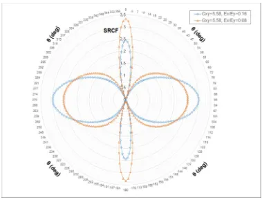
respectively. This phenomenon is associated with a shift in the position of the point with
the highest SRCF around the edge of hole as demonstrated in Fig. 7. For all stacking
sequences, maximum SRCF takes place at 90o angle from the load direction; however,
for laminates with a dominant number of 90o and no 0o plies, this angle becomes zero.
For Peer Review
Such extremes of anisotropy are not common in engineering structures as they reduce
performance in other aspects such as tolerance to impact.
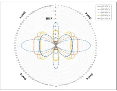
The use of more angle plies increases the homogenised shear modulus of a composite
laminate leading to less stiff laminates in the loading direction, i.e. smaller value of Ex.
In this study, the laminates having high homogenised shear modulus are generated by
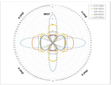
using solely angle plies with mechanical properties given in Table 3, i.e. ((15/-15)7)s,
((30/-30)7)s, ((45/-45)7)s, ((60/-60)7)s, ((75/-75)7)s. Such laminates do not possess any 0 o
and 90o plies and they represent only one point in the graphs of Fig. 6. Therefore, they
are studied separately as shown in Fig. 8. This figure shows that minimum SRCF of
2.61 takes place for the situation where all plies have 60o orientation, i.e. ((60/-60)7)s for
uni-axial loading. It is worth noting that this stacking sequence does not have the
highest homogenised shear modulus. Thus, this observation suggests that, in the
absence of 0o and 90o plies, the highest homogenised shear modulus, i.e. ((45/-45)7)s,
does not necessarily give the lowest SRCF. Moreover, it is evident from the graph that
as the plies angle increases from 15o to 75o, the angle made between the direction of
loading and the point with highest SRCF decreases from 900 to 0o, respectively.
However, introduction of 0o or 90o plies enforces the laminate to have SRCF either at
0o or 90o depending on the number of plies used in those directions. Fig. 9 and Fig. 10
illustrate the quantity of SRCF for various values of Ex/Ey for bi-axial loading of
λ
=0.5 andλ
=-0.5, respectively. In all figures, Nx is assumed to be always in tension (positive) and Ny is either in compression (negative) or in tension depending on thesign of
λ
. The general trend, in both cases, suggests that increase in homogenisedshear modulus of laminate (Gxy) leads to lower SRCF. However, for a given Gxy and
λ
=0.5 (Fig. 9), the lower the ratio of Ex/Ey the lower the SRCF becomes. Whenλ
3For Peer Review
=-0.5 (Fig. 10), the combined effect of tension and compression loading results in
minimal SRCF at around Ex/Ey=0.5 for most laminates.
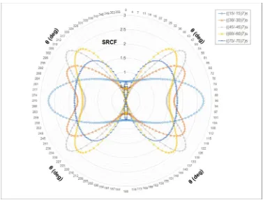
As illustrated in Fig. 11 and Fig. 12, in purely angle ply laminates, minimum SRCF of
1.90 and 2.71 occur for stacking sequences ((75/-75)7)s and ((45/-45)7)s at
λ
=0.5 andλ
=-0.5, respectively. As mentioned previously, Gxy for stacking sequence ((75/-75)7)sis 12.00 GPa as opposed to 31.23 GPa associated to ((45/-45)7)s. However, in this
particular case, the minimum SRCF does not occur for the laminate with the highest
xy
G . This could be due to the Poisson’s ratio effect. For instance, for ((75/-75)7)s with
λ
=0.5, Nx produces tensile and compressive strains inx
and y directions,respectively. On the contrary, Ny produces tensile strain in y and compressive strain
in
x
direction. Superimposing these strains and considering Poisson’s ratio of thelaminate as
υ
yx=0.09 andυ
xy=0.85 suggests relief in load intensity inx
directionleading to a lower SRCF compared to that of ((45/-45)7)s and
λ
=-0.5. On the otherhand, when stacking sequence is ((45/-45)7)s and
λ
=-0.5, consideringυ
yx=0.72 andxy
υ
=0.72, tensile load in thex
direction brings about tensile strain in thex
andcompressive strain in the y direction whereas compressive load in y direction causes
the laminate to undergo compressive strain in the y direction and tensile strain in the
x
direction. This, along with equal Poisson’s ratio in both directions leads tointensification of load in the
x
direction bringing about SRCF of 2.71. It is worth notingthat the loading condition, i.e. bi-axial, has shifted the location of point with highest
SRCF around the edge of the hole.
Fig. 13 and Fig. 14 illustrate the quantity of SRCF for various values of Ex/Ey for
bi-axial loading of
λ
=-1.00 andλ
=1.00, respectively. As depicted in Fig. 13, forλ
=-3For Peer Review
1.00, an apparent decrease of SRCF with increase of Gxy is noticeable. For this case
y x E
E / =1 gives the lowest SRCF for all laminates and beyond this point SRCF
increases. However, strange behaviour is observed for
λ
=1.00 as shown in Fig. 14. For this case, increase of Gxy up to 16.55GPa is accompanied by reduction of SRCF.Despite increase of Gxy from 19.29GPa to 27.51GPa, SRCF increases.
Fig. 15, Fig. 16 and Fig. 17 illustrate combined effects of loading ratio
λ
and laminate stiffness ratio, i.e. Ex/Ey, on SRCF for three homogenised shear modulus values ofxy
G =5.58GPa, Gxy=16.58GPa and Gxy=23.86GPa, that represent low, medium and
high shear stiffness values within the laminates population space of study, respectively.
Fig. 15a and Fig. 15b both show that the positive
λ
generally yields lower SRCF with the minimum being 1.96 pertinent toλ
=1.5. It is evident from the graph that forλ
<0, SRCF becomes minimum at an Ex/Ey ratio close to value ofλ
. For example,minimum SRCF for
λ
=-2.0,λ
=-1.5 andλ
=-0.5 takes place at Ex/Ey=2.11, 1.63 and 0.47, respectively. A similar trend can be observed in Fig. 16 and Fig. 17 as Gxyincreases from 5.58GPa to 16.58GPa and 23.86GPa. In most cases, the lowest SRCF
for all shear moduli occurs when
λ
=1.0.5 Conclusions
The analytical tool was used to visualise the effect of laminate anisotropy and loading
direction on the SRCF around a circular hole in an infinite plate. This was achieved by
creating a population of laminates and loadings that are representative of thin-walled
panels used in the aerospace industry. It is expected that similar graphs can be used
by designers of composite structures to optimise the laminate geometry in the regions
of holes. This further enables efficient laminates without resorting to complicated
mathematics or time-consuming FEA. 3
For Peer Review
It was shown that composite laminates demonstrate a very complex behaviour towards
loading, stacking sequence, i.e. resulting in homogenised stiffness, and SRCF. In the
absence of purely angle ply laminates, it was demonstrated that increase in
homogenised shear modulus of laminate leads to reduction in SRCF. However, this
cannot hold true for angle ply laminates as the effects of Poisson ratio becomes
predominant. Finally, it was illustrated that positive
λ
yield the lowest SRCF comparedto other types of loading investigated in this study.
Appendix A
A1 Mapping function
The conformal mapping function is used to map the infinite area external to the hole in
a complex Z-plane, i.e. z=x+iy, onto the external area of a unit circle (
ζ
>
1
) in theζ -plane, i.e. ζ =ξ+iη, or in the polar format as
ζ
=ρ
eiθ, as illustrated in Fig. A1. Themapping function that conformably maps an elliptical hole having major axis
a
andminor axis
b
onto a unit circle for an isotropic material is as follows:( )
2
;R a b
b a
b a m
m R z
+ = + − =
+ = =
ζ ζ ζ
ω
(A1)
For anisotropic materials due to a fully populated compliance matrix, deformations go
through affine transformation. Therefore, by incorporating complex values of
anisotropy, i.e. replacing
i
withs1 and s2, the mapping function becomes:( )
[
(
ρ
)
θ
(
ρ
)
θ
]
ζ
ζ
ζ
ω
R
m
R
m
2cos
s
2m
sin
z
=
+
+
j−
+
=
=
(A2)After simplification and considering that
+
=
ζ
ρ
ρ
ζ
θ
2
1
cos
and
−
−
=
ζ
ρ
ρ
ζ
θ
2
sin
i
the above equation for anisotropic materials takes the form: 3
For Peer Review
j j j j j j j j is n j is n m n m n R z − = = + = + + + = = 1 2 , 1 ; 1 2 ) ( * * 2 2ζ
ζ
ρ
ζ
ζ
ρ
ζ
ω
(A3)For the edge of the hole, i.e.
ζ
=
1
, Eq. (A3) simplifies to:
+
+
+
=
=
ζ
ζ
ζ
ζ
ζ
ω
R
n
m
n
m
z
j j j j*
1
2
)
(
(A4)A2 Calculation of stress functions
The existence of a discontinuity such as a hole in the plate alters the stress field in the
plate. In order to obtain the stress function for such a problem and due to linear and
elastic behaviour of the material, the principle of superposition is used. The problem is
split into two stages as follows:
A2.1 Stage 1
At this stage, the plate without a hole subjected to remote external loading R x
N , R
y
N
and R xy
N is considered. The fictitious boundary conditions at the location of the hole are
regarded as g1 and g2 as shown in Fig. A2.
Stress functions to be determined for this stage are φ1(z1) and ψ1(z2) satisfying g1
and g2 boundary conditions. In order to obtain stress functions for this stage the
following is assumed:
Gi F z E z + = = ) ( ) ( 2 ' 1 1 ' 1 ψ φ (A5)
Therefore, we have:
For Peer Review
where E, F and G are real value constants that will be determined by substituting
Eq. (A5) into Eq. (13):
[
]
[
]
2 1 2 2 2 2 1 2 1 2 2 2 1 2 1 2 1 2 2 2 1 2 1 2 2 2 2 2 2 5 . 0 ) ( ) ( 2 2 ) 2 ( ) ( ) ( 2 2 ) (β
α
α
β
β
α
α
α
α
α
β
α
β
β
α
α
α
β
α
E F N G N N N F N N N E xy xy x y xy y x + + = − − − − − − − = − − − + + + = (A7)The resultant of forces, i.e. boundary conditions, around the contour of fictitious hole in
ζ -plane is represented as:
[
]
[
(
)
(
)
]
Re
2
)
(
)
(
Re
2
2 1 2 1 1 1 2 2 1 1 1 1z
s
z
s
g
z
z
g
ψ
φ
ψ
φ
+
=
+
=
(A8) Therefore:[
]
[
1 1 2 2]
2 2 1 1
)
(
Re
2
)
(
Re
2
z
Gi
F
s
Ez
s
g
z
Gi
F
Ez
g
+
+
=
+
+
=
(A9)A2.2 Stage 2
This stage considers the plate with the hole in the absence of remote loading. Stress
functions to be determined for this stage are φ2(z1) and ψ2(z2)satisfying some
boundary conditions. In order to obtain the solution for which the total loads on the
contour of the hole are zero, i.e. traction free boundary condition on which only
tangential stresses exist and therefore shear and radial stresses vanish, it is essential
for the boundary condition at the edge of the hole to be 1 ' 1 g
g =− and 2
' 2 g
g =− . In other
words, boundary conditions are equal and opposite signs of stage 1, as shown in Fig.
A2. Hence;
[
]
[
1 1 2 2]
For Peer Review
By expanding the term and considering that mr r r m
r+ =1+ for r=
ζ
=eiθ we have:(
)
(
)
(
)
(
)
+ + + + + − = + + + + + − = r m r H H mr r H H g r m r H H mr r H H g 3 4 4 3 ' 2 1 2 2 1 ' 1 1 1 (A11) where(
)
[
]
(
)
[
]
(
)
[
]
(
)
[
1 1 2 2]
4 2 2 1 1 3 2 1 2 2 1 1
*
*
2
2
*
*
2
2
n
iG
F
s
En
s
R
H
n
iG
F
s
En
s
R
H
n
iG
F
En
R
H
n
iG
F
En
R
H
+
+
=
+
+
=
+
+
=
+
+
=
(A12)Based on Sharma et al. 17, the Schwarz Integral Formula is used for calculation of
stress functions in the absence of remote loading in conjunction with boundary
conditions g1' and g2' as below:
(
)
(
)
(
)
(
)
21 ' 2 ' 1 1 2 1 2 1 1 ' 2 ' 1 2 2 1 2
4
)
(
4
)
(
λ
ζ
ζ
π
ξ
ψ
λ
ζ
ζ
π
ξ
φ
ξ ξ+
−
+
−
−
−
=
+
−
+
−
−
=
∫
∫
= =r
dr
r
r
g
g
s
s
s
i
r
dr
r
r
g
g
s
s
s
i
(A13)where λ1 and λ2 are some imaginary constants that have no impact on stress field so
can be ignored. ζ is an arbitrary point of the plane of a complex variable. iθ
e
r = is
the boundary value of ζ on the circle of unit radius. Considering;
0
.
.
,
4
.
.
1
1 1=
−
+
=
−
+
∫
∫
= = ζ ζζ
ζ
ζ
π
ζ
ζ
r
dr
r
r
r
i
r
dr
r
r
r
k kk (A14)
For Peer Review
+ − = + =ζ
ζ
ζ
ψ
ζ
ζ
ζ
φ
m l l m l l 4 3 2 2 1 2 ) ( ) ( (A15) where;(
) (
)
[
]
(
) (
)
[
]
(
) (
)
[
]
(
) (
)
[
1 2 1 4 3]
2 1 4 4 3 2 1 1 2 1 3 3 4 1 2 2 2 1 2 4 3 2 1 2 2 1 1 1 1 1 1 H H H H s s s l H H H H s s s l H H H H s s s l H H H H s s s l + − + − = + − + − = + − + − = + − + − = (A16)
A3 Final stress function
The final stress function of the problem is the summation of previously obtained stress
functions as:
)
(
)
(
)
(
)
(
)
(
)
(
2 2 2 1 2 1 2 1 1 1z
z
z
z
z
z
ψ
ψ
ψ
φ
φ
φ
+
=
+
=
(A17)By combining Eqs (12), (A5), (A14) and (A16), the final resultant force components are
calculated as;
[
]
[
]
[
( ) ( )]
Re 2 ) ( ) ( Re 2 ) ( ) ( Re 2 2 ' 2 2 1 ' 2 1 2 ' 2 1 ' 2 2 ' 2 2 2 1 ' 2 2 1 z s z s N N z z N N z s z s N N R xy xy R y y R x x ψ φ ψ φ ψ φ + − = + + = + + = (A18)where NxR,
N
yR and R xyN
are remote applied stress resultants inx
, y directions and xyFor Peer Review
1 2 4 2 3 ' 2 2 2 2 1 ' 2 2 * 2 2 * 2 2 2 2 ' 2 2 ' 2 1 ' 2 1 ' 2 ) ( ) ( 1 1 2 1 2 ) ( ) ( ) ( ) (ζ
ζ
ζ
ψ
ζ
ζ
ζ
φ
ζ
ζ
ζ
ζ
ζ
ρ
ρ
ζ
ζ
ζ
ψ
ψ
ζ
ζ
φ
φ
ρ m l l m l l m n m n R d dz m n m n R d dz d dz z d dz z j j j j j j + = − − = − + − = → − + − = = == (A19)
In order to transform stress resultants from Cartesian system to Curvilinear system, the
following transformation is required 34;
α ρθ ρ θ ρ θ i xy x y y x
e
iN
N
N
iN
N
N
N
N
N
N
2)
2
(
2
=
−
+
+
−
+
=
+
(A20)where Nθ, Nρ and Nρθ are circumferential, radial and tangential stress resultants,
respectively. The term iα
e2 is defined as 34;
( )
( )
ζ
ω
ζ
ω
ρ
ζ
α'
'
2 2 2i=
e
(A21)Since no load is applied to the hole, only circumferential stresses can exist, i.e.
0
= = ρ
ρθ N
N , therefore;
θ N N
Nx+ y = (A22)
References
1. Makki MM, Chokri B. Experimental, analytical, and finite element study of stress
concentration factors for composite materials. J Compos Mater 2017; 51: 1583–
1594.
For Peer Review
orthotropic laminates. Procedia Technol 2016; 23: 156–162.
3. Jain NK, Mittal ND. Finite element analysis for stress concentration and
deflection in isotropic, orthotropic and laminated composite plates with central
circular hole under transverse static loading. Mater Sci Eng A 2008; 498: 115–
124.
4. Henshaw JM, Sorem JR, Glaessgen EH. Finite element analysis of ply-by-ply
and equivalent stress concentrations in composite plates with multiple holes
under tensile and shear loading. Compos Struct 1996; 36: 45–58.
5. Haque A, Ahmed L, Ramasetty A. Stress concentrations and notch sensitivity in
woven ceramic matrix composites containing a circular hole-an experimental,
analytical, and finite element study. J Am Ceram Soc 2005; 88: 2195–2201.
6. Bonora N, Costanzi M, Marchetti M. A computational procedure to calculate
stress-strain field around simple shape holes in composite laminates. Comput
Struct 1994; 53: 1167–1179.
7. Bonora N, Costanzi M, Marchetti M. On closed form solution for the elastic
stress field around holes in orthotropic composite plates under in-plane stress
conditions. Compos Struct 1993; 25: 139–156.
8. Weißgraeber P, Felger J, Geipel D, et al. Cracks at elliptical holes: Stress
intensity factor and Finite Fracture Mechanics solution. Eur J Mech A/Solids
2016; 55: 192–198.
9. Batista M. On the stress concentration around a hole in an infinite plate subject
to a uniform load at infinity. Int J Mech Sci 2011; 53: 254–261.
10. Chauhan MM, Sharma DS, Dave JM. Stress intensity factor for hypocycloidal
hole in finite plate. Theor Appl Fract Mech 2016; 82: 59–68.
11. Chauhan MM, Sharma DS. Stresses in finite anisotropic plate weakened by 3
For Peer Review
12. Zappalorto M, Carraro PA. An engineering formula for the stress concentration
factor of orthotropic composite plates. Compos Part B Eng 2015; 68: 51–58.
13. Russo A, Zuccarello B. An accurate method to predict the stress concentration in
composite laminates with a circular hole under tensile loading. Mech Compos
Mater 2007; 43: 359–376.
14. Hufenbach W, Grüber B, Gottwald R, et al. Analytical and experimental analysis
of stress concentration in notched multilayered composites with finite outer
boundaries. Mech Compos Mater 2010; 46: 531–538.
15. Muskhelishvili NI. Some Basic Problems of the Mathematical Theory of
Elasticity. Springer Netherlands. Epub ahead of print 1977. DOI:
10.1007/978-94-017-3034-1.
16. Neuber H. G. N. Savin, Stress Concentration around Holes. XI + 430 S. m. 208
Abb. u. 77 Tafeln. Oxford/London/New York/Paris 1961. Pergamon Press. Preis
geb. 84 s. net. ZAMM - Zeitschrift für Angew Math und Mech 1962; 42: 265–265.
17. Sharma DS. Stresses around polygonal hole in an infinite laminated composite
plate. Eur J Mech A/Solids 2015; 54: 44–52.
18. Ukadgaonker VG, Rao DKN. Stress distribution around triangular holes in
anisotropic plates. Compos Struct 1999; 45: 171–183.
19. Jafari M, Ardalani E. Stress concentration in finite metallic plates with regular
holes. Int J Mech Sci 2016; 106: 220–230.
20. Sharma DS. Moment distribution around polygonal holes in infinite plate. Int J
Mech Sci 2014; 78: 177–182.
21. Ukadgaonker VG, Rao DKN. A general solution for stresses around holes in
symmetric laminates under inplane loading. Compos Struct 2000; 49: 339–354.
22. Ukadgaonker VG, Kakhandki V. Stress analysis for an orthotropic plate with an 3
For Peer Review
irregular shaped hole for different in-plane loading conditions - Part 1. Compos
Struct 2005; 70: 255–274.
23. Jain NK, Mittal ND. Finite element analysis for stress concentration and
deflection in isotropic, orthotropic and laminated composite plates with central
circular hole under transverse static loading. Mater Sci Eng A 2008; 498: 115–
124.
24. Khechai A, Tati A, Guettala A. Finite element analysis of stress concentrations
and failure criteria in composite plates with circular holes. Front Mech Eng 2014;
9: 281–294.
25. Othman A, Jadee KJ, Ismadi M-Z. Mitigating stress concentration through
defense hole system for improvement in bearing strength of composite bolted
joint, Part 1: Numerical analysis. J Compos Mater 2017; 51: 3685–3699.
26. Darwish F, Gharaibeh M, Tashtoush G. A modified equation for the stress
concentration factor in countersunk holes. Eur J Mech A/Solids 2012; 36: 94–
103.
27. Darwish F, Tashtoush G, Gharaibeh M. Stress concentration analysis for
countersunk rivet holes in orthotropic plates. Eur J Mech A/Solids 2013; 37: 69–
78.
28. Zhao GH, Tong JW, Shen M. Numerical Analysis and Experimental Validation of
Interlaminar Stresses of Quasi-isotropic APC-2/AS-4 Laminate with a Central
Hole Loaded in Tension. J Thermoplast Compos Mater 2010; 23: 413–433.
29. Microsoft. Excel.
30. MSC Software Corporation. Nastran 2016.
31. Kassapoglou C. Review of laminate strength and failure criteria. 2nd ed.
Hoboken, N.J. : Wiley ; Chichester : John Wiley [distributor], 2013. Epub ahead 3
For Peer Review
32. Pandita SD, Nishiyabu K, Verpoest I. Strain concentrations in woven fabric
composites with holes. Compos Struct 2003; 59: 361–368.
33. Lekhnitskii SG. Theory of elasticity of an anisotropic elastic body. San
Francisco-Holden-Day Inc, 1963.
34. Pan Z, Cheng Y, Liu J. Stress analysis of a finite plate with a rectangular hole
subjected to uniaxial tension using modified stress functions. Int J Mech Sci
2013; 75: 265–277. 3
For Peer Review
Table 1: CFRP material used for results generation
Material E11
(GPa)
22
E (GPa)
12
G
(GPa) υ12 t (mm)
Hexcel 8552 AS4 unidirectional
[image:25.612.92.523.209.337.2]prepreg at 190gsm 120.00 10.00 5.58 0.305 0.18
Table 2: Material and lay-up used for FEA validation
Validation
ID Material
Lay-up/ Loading
Hole
shape 11
E (GPa)
22
E (GPa)
12
G
(GPa) υ12
Val-A
Hexcel 8552S AS4 3K Plain Weave Fabric
(45/0/-45/90/0)s
/ bi-axial
Circular (a=10 mm,
b=10 mm)
62.00 62.00 4.20 0.05
Val-B (45/0/-45/90/0)s
/ uni-axial
Elliptical (a=20 mm,
b=10 mm)
Table 3: Mechanical properties of purely angle ply laminates
Stacking sequence
x
E (GPa)
y
E
(GPa) Ex/Ey
xy
G
(GPa)
υ
xyυ
yx((15/-15)7)s 99.04 10.26 9.66 12.00 0.09 0.85
((30/-30)7)s 47.24 11.84 3.99 24.82 0.30 1.20
((45/-45)7)s 19.20 19.20 1.00 31.23 0.72 0.72
((60/-60)7)s 11.84 47.24 0.25 24.82 1.20 0.30
((75/-75)7)s 10.26 99.04 0.10 12.00 0.85 0.09
For Peer Review
Fig. 1: Schematic representation of geometry, loading and boundary condition for FEA 3
For Peer Review
Fig. 2: Contour plot of stresses for an infinite composite plate containing a circular hole of radius 10mm under bi-axial loading (Val-A), i.e. Nx=Ny=280N/mm; (a) Normal stress in x-direction, (b) Normal stress in
y-direction and (c) Shear stress in xy plane
For Peer Review
Fig. 3: Contour plot of stresses for an infinite composite plate containing an elliptical hole of radius 10mm under uni-axial loading (Val-B), i.e. Nx=280N/mm; (a) Normal stress in x-direction, (b) Normal stress in y
-direction and (c) Shear stress in xy plane
For Peer Review
Fig. 4: Comparison of stress resultant output at the edge of a circular hole for both analytical and FE approaches, i.e. Normal stress resultant in (a) x-direction and (b) y-direction and (c) shear in xy plane
For Peer Review
Fig. 5: Comparison of stress resultant output at the edge of an elliptical hole for both analytical and FE approaches, i.e. Normal stress resultant in (a) x-direction and (b) y-direction and (c) shear in xy plane
For Peer Review
Fig. 6: Semi-log plot of SRCF vs Ex/Ey for loading λ=0. Unit of stiffness is GPa
For Peer Review
Fig. 7: Distribution of the SRCF around the edge of the hole for uni-axial loading for Gxy=5.58GPa for
stacking sequences of (9013/0)s and (90)28 associated to Ex/Ey of 0.16 and 0.08, respectively. The load is
applied at 0o direction
For Peer Review
Fig. 8: Plot of SRCF Ex/Ey for loading λ=0 and angle ply sequences only
For Peer Review
Fig. 9: Semi-log plot of SRCF vs Ex/Ey for loading λ=0.5. Unit of stiffness is GPa
For Peer Review
Fig. 10: Semi-log plot of SRCF vs Ex/Ey for loading λ=-0.5, Nx is in tension and Ny is in compression. Unit of stiffness is GPa
For Peer Review
Fig. 11: Plot of SRCF vs Ex/Ey for loading λ=0.5 for angle ply sequences only
For Peer Review
Fig. 12: Plot of SRCF vs Ex/Ey for loading λ=-0.5 for angle ply sequences only
For Peer Review
Fig. 13: Semi-log plot of SRCF vs Ex/Ey for loading λ=-1.00. Unit of stiffness is GPa
For Peer Review
Fig. 14: Semi-log plot of SRCF vs Ex/Ey for loading λ=1.00. Unit of stiffness is GPa
For Peer Review
Fig. 15: Graphs of SRCF for various Ex/Ey and load ratio λ for laminates with Gxy=5.58GPa, (a) 3D surface graph and (b) semi-logarithmic 2D graph
For Peer Review
Fig. 16: Graphs of SRCF for various Ex/Ey and load ratio λ for laminates with Gxy=16.58GPa, (a) 3D surface graph and (b) semi-logarithmic 2D graph
For Peer Review
Fig. 17: Graphs of SRCF for various Ex/Ey and load ratio λ for laminates with Gxy=23.86GPa, (a) 3D surface graph and (b) semi-logarithmic 2D graph
For Peer Review
Fig. A1: Illustration of mapping a hole having an irregular shape in an infinite plate onto a unit circle using mapping functions
For Peer Review
Fig. A2: Use of principle of superposition for calculation of stress functions 3