Reproducibility of Scientific Workflows Execution
using Cloud-Aware Provenance (ReCAP)
Khawar Hasham, Kamran Munir
Abstract
Provenance of scientific workflows has been considered a mean to provide workflow reproducibility. However, the provenance approaches adopted so far are not applicable in the context of Cloud because the provenance trace lacks the Cloud information. This paper presents a novel approach that collects the Cloud-aware provenance and represents it as a graph. The workflow execution reproducibility on the Cloud is determined by comparing the workflow provenance at three levels i.e., workflow structure, execution infrastructure and workflow outputs. The experimental evaluation shows that the implemented approach can detect changes in the provenance traces and the outputs produced by the workflow.
Index Terms
Scientific Workflows, Cloud Computing, Provenance Management, Provenance Graph, Reproducibility
I. INTRODUCTION
The scientific community is experiencing a data deluge due to the generation of large amounts of data in modern scientific experiments that include projects such as the Large Hadron Collider (LHC)1, and projects such as N4U [1] [?]. Cloud computing [2] has emerged as a new computing and storage paradigm, which is dynamically scalable and usually works on a pay-as-you-go cost model. It aims to share resources to store data and to host services transparently among users at a massive scale [3]. Its ability to provide an on-demand computing infrastructure with scalability enables distributed processing of complex scientific workflows for the scientific community [4]. Research [5] is being carried out to assess the feasibility of executing workflows on the Cloud.
An important consideration during this data processing is to gather data that can provide detailed information about the data and the processes involved to verify and repeat a workflow execution. Such a data is termed as Provenance in the scientific literature [6]. This data can be used to debug and verify the execution of a workflow, to aid in error tracking and reproducibility. This enables scientists to iterate on the scientific method, to evaluate the process and results of other experiments and to share their own experiments with other scientists [7]. Whilst capturing a provenance trace is necessary it is not sufficient to allow a computation to be repeated due to lack of critical information required for execution [8]. A research study [9] conducted to evaluate the reproducibility of scientific workflows has shown that around 80% of the workflows cannot be reproduced, and 12% of them are due to the lack of information about the execution environment. The situation becomes more challenging in the context of the Cloud computing, which presents a dynamic environment in which resources are provisioned on-demand. The execution of scientific workflows in Clouds brings to the fore the need to collect provenance information, which is necessary to ensure the reproducibility of these experiments. Since scientific workflows typically model a dataflow with a structure resembling a directed acyclic graph (DAG), the provenance comparison approaches measure similarity between two given provenance traces using graphs [10]. However, such approaches lack the information about the Cloud resources in provenance graph comparison, which is the main focus of this paper.
The ReCAP framework as presented in this paper, augments workflow provenance with the Cloud infrastructure information; and uses it to provision similar execution environment(s) and reproduces the execution of a given workflow. In particular, this paper focuses on the ReCAP’s provenance comparison approaches that are devised to determine reproducibility by analysing the provenance traces at three levels; (a) structure level (b) infrastructure level and (c) workflow outputs. The structural similarity is determined by converting the provenance traces into a graph model and then analysing the graph similarity. The details of other components of ReCAP system are presented in [11] and [12].
The main aspects of the work presented in this article are as follows: section II presents related work. Section III presents the architecture of ReCAP. Section IV discusses the graph representation adopted to model provenance traces into graph and also presents two different provenance comparison approaches. Section V presents a detailed evaluation of ReCAP’s capability to re-execute a workflow on Cloud and compare provenance traces, and finally section VI presents some conclusions and directions for future work.
Kamran Munir is the corresponding author and can be reached at [email protected]
Department of Computer Science and Creative Technologies (CSCT), University of the West of England (UWE), Frenchay Campus, Coldharbour Lane, Bristol, BS16 1QY, United Kingdom
II. RELATEDWORK
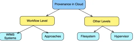
[image:2.612.212.399.202.396.2]Grid-based workflow management systems help in capturing not only the workflow retrospective provenance but some systems such as [13], [14] also support workflow prospective provenance. However, this paper is focusing on the workflow execution provenance on the Cloud, rather than the provenance of a workflow itself (e.g. design changes). Since these systems were developed for the Grid, the provenance collected by these systems lack the information about the Cloud resources. Some systems such as Pegasus/Wings [14] that also supports the evolution of a workflow. However, this paper is focusing on the workflow execution provenance on the Cloud, rather than the provenance of a workflow itself (e.g. design changes). Moreover, Taverna [15] and Kepler [16] are popular workflow engines used in the scientific domain and capable of capturing provenance data and querying and exporting the provenance graph [28]. However, the provenance collected by these systems lack the information about the Cloud resources used during a workflow execution. Figure 1 provides a summary of Grid-based workflow management systems.
Fig. 1:Summary of Grid-based Workflow Management Systems
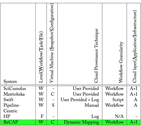
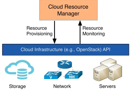
This paper focuses on the information about the Cloud resources, not the hypervisor (as in [17], [18]) or file system (as in [19]) used during workflow execution. Figure 2 illustrates the provenance management levels in the Cloud. Using workflow provenance in graph format has been proposed to compare provenance traces [20], [21]. Woodman et al. [21] propose the use of provenance graph to determine the changes in the version of services or tasks used in a workflow. It converts the workflow provenance trace in an OPM complaint graph format and then compare the provenance traces. Contrary to this, The presented work in this paper augments the workflow provenance with Cloud resource information, representing it in a graph model, and uses it to compare provenance traces. This helps in determining workflow reproducibility involving the Cloud information. [20] proposed an approach that performs a comparison on workflow provenance graphs to determine differences in reproduced workflows. Similarly, [22] proposed the use of structural comparison to measure the similarity between two given provenance traces using graphs. Aforementioned approaches cover different aspects such as workflow versioning etc. of workflow reproducibility in the comparison, however the lack the support and modeling of the Cloud infrastructure information in the provenance graph, which is the focus of this paper.
Fig. 2: The provenance management levels in the Cloud
[image:2.612.199.416.582.651.2]As the emphasis of this paper is on measuring the similarity between two workflow execution provenance traces using graphs, it does not focus on identifying the missing provenance information. In the presented approach discussed in this paper, it is assumed that the Cloud resource information collected from the Cloud middleware is correct. Moreover, the proposed approach does not use the user provided semantic information for processing provenance graph unlike the approach proposed in [26]. Various other existing approaches (e.g. [27], [28]) and research studies (e.g. [29]) operate along with the job on the virtual machine. Similarly, CARE [28] is designed to reproduce a job execution. On the contrary, our approach works outside the virtual machine and therefore does not interfere with job execution.
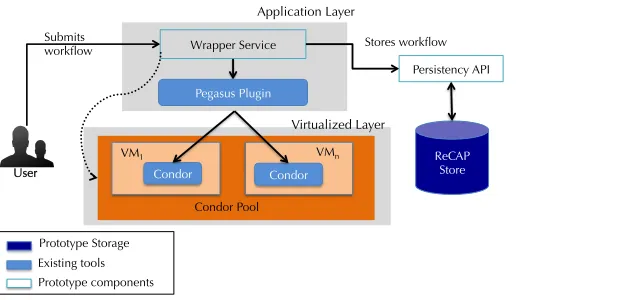
[image:3.612.191.421.221.426.2]In summary, these approaches capture provenance information at different levels. However, they do not link them together to provide the Cloud-aware work ow provenance information for a user, which is the main objective of this research study. Furthermore, there are a few approaches such as Matriohska that do not provide Cloud information capturing approach rather they rely on user provided information. Another objective of this research study is to devise an approach that can automatically capture the information related to a Cloud resource and then link it with the work ow provenance. A tabular summary of the literature survey is provided in Figure 3.
Fig. 3:Summary of Cloud-based Provenance Approaches
III. RECAP: REPRODUCEWORKFLOW EXECUTION USINGCLOUD-AWAREPROVENANCE
ReCAP has been designed on the configuration and plugin-based mechanism. With this mechanism, support for new workflow management systems, mapping algorithms etc. can be easily added without changing the core of the system. There are seven key components in this design. They are the (i) WMS Wrapper Service, (ii) WS Client, (iii) WMS Layer, (iv) Cloud Layer, (v) Aggregator, (vi) WF-Repeat, and (vii) Comparator. Each of these components can further have their sub-components which are also discussed in this section. Figure 4 shows the detailed architecture of ReCAP and mutual interaction among its components.
A. ReCAP Configuration
ReCAP is designed using a plugin based approach and this requires a set of configuration parameters to drive the overall system. Consequently, the key aspects of the ReCAP such as WMS components, mapping algorithms, persistence API that interacts with the workflow provenance, the ReCAP databases and the Cloud middleware are driven by the configuration parameters. These configurations (shown as ReCAP configsin Figure 4) are divided into seven main categories (see Table I).
B. WMS Wrapper Service
WMS Wrapper Service submission/monitoring WS Client Aggregator WF-Repeat PersistencyAPI Comparators ReCAP configs service configs Parser Monitor WMS/Pegasus Cloud Resource Manager Cloud Storage Manager User WMS Layer Cloud Layer C lo u d l a y e r In fo rm a ti o n submit repeat shared object
interaction between ReCAP components
[image:4.612.196.413.54.268.2]interaction between ReCAP and WMS/Cloud components user workflow workflow provenane VM storage WMS DB ReCAP Store
Fig. 4:Architecture of the ReCAP system TABLE I:Different types of configurations used in ReCAP
Configuration Description
cloud settings Provides a large number of parameters which are mainly used to access the Cloud middleware. Since the ReCAP prototype is using Apache Libcloud2API, which can interact with various Cloud middlewares, these parameters can be changed to accommodate a new Cloud middleware without any change in the code.
storage settings Provides parameters for the ReCAP to establish connection with the Cloud storage service to retrieve information about the workflow’s data files stored on the Cloud.
db settings Provides parameters used to connect with the database of the workflow management system. For this prototype, MySQL database settings for Pegasus have been used.
cloudprov settings Provides parameters used to connect with the relational database (discussed in Section III-J) used in this prototype. Another important parameter in this isMAPPING TYPE, which informs the ReCAP to load the appropriate mapping algorithm.
WMS settings Depending upon the used workflow management system, these parameters can be changed. For instance,wms monitorparameter loads the appropriate monitoring component that monitors the workflow state in the database configured in above settings. This component is WMS specific and so is its implementation.
WrapperService To interact with the WrapperService, the Client component requires connection information such as service URL and user credentials. This section provides these details.
log settings In order to log the inner activities of ReCAP, logging is provided and it is controlled by this parameter.
Application Layer Condor Virtualized Layer Submits workflow Persistency API ReCAP Store Stores workflow VM1 Condor VMn Existing tools Prototype components Prototype Storage User Wrapper Service Condor Pool Pegasus Plugin
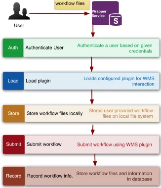
Fig. 5:Interaction of Service Wrapper with overall system
A user accesses the Wrapper Services over HTTP and requests to submit his workflow. In this request, he will provide the abstract representation of his workflow i.e. DAX and its associated configurations, which are specific to the underlining workflow management system. In the case of Pegasus, he will provide a DAX file and a site file that provides information about storage, environment variables and workflow constraints. Upon receiving the request, the Service Wrapper first authenticates the user with the provided credentials in the service request. This enables the service to prevent unauthorised access to the underlying resources.
[image:4.612.178.489.471.621.2]interact with the underlining WMS. In the ReCAP prototype, a Pegasus plugin is implemented that uses Pegasus commands and its database. The plugin stores the user provided files locally and then submits them to Pegasus usingpegasus plan3. Once the workflow has been submitted, Pegasus provides a unique identifier for this workflow and that is returned back to the user or a component as a response to its workflow submission request. This response is returned in Javascript Object Notation (JSON) format, which is compact, flexible (schemaless) and easier to use. Upon successful submission of the user’s workflow, the Service Wrapper stores the provided files in the database for later use in reproducing a workflow execution (discussed later in Section III-J). The Figure 6 illustrates the flow of activities within the Service Wrapper for submitting a user workflow.
workflow files
Wrapper Service
Auth Authenticate User Authenticate a user based on given
credentials
Load Load plugin Loads configured plugin for WMS interaction
Store Store workflow files locally Stores user provided workflow files on local file system
Record Record workflow info.Store workflow files and information
in database Submit Submit workflow Submit workflow using WMS plugin
[image:5.612.224.387.158.348.2]User
Fig. 6:Flow chart of Wrapper Service to process a workflow
The following main operations are supported at the time of writing, which can be called from the service Client component. • submit: This operation is used to submit a workflow to the underlying workflow management system, which is Pegasus
in this prototype. All required files are passed in the service request, which are processed accordingly.
• wms get file: This operation is used to retrieve files (job outputs, workflow submission output) stored within the workflow management system’s work directory. It takes two arguments i.e. (1) job information and (2) the directory location to find the requested files. This operation is used while processing the job logs in mapping components.
• jobmon: This operation is Condor-specific as it attempts to retrieve the current status of the job running on Condor. It helps in retrieving the host information from the Condor pool on which a job is running.
• cpool mips: This operation is used to to retrieve the MIPS of the machines in the Condor pool. MIPS or KFLOPS are one way to specify the execution performance of a machine and it can affect a job execution performance.
C. WMS Layer
As discussed earlier, the design philosophy of ReCAP is plugin-based in order to provide support for extensibility. A literature review has shown that multiple workflow management systems such as Pegasus, Chimera, Taverna and Kepler etc., provide either the hostname or the IP of the machine on which a job was executed. Therefore, it has been considered to enable support for multiple workflow management systems by adopting a plugin-based design. This section provides detail about the WMS Monitor and Parser components. During mapping process, this layer loads appropriate plugin implementation based upon the configuration parameters (see WMS settings in Table I). In ReCAP, Pegasus-based plugins have been implemented.
1) Monitor: This component presents a threaded implementation which enables continuous monitoring of a workflow
execution. In order to perform monitoring operations, it interacts with the WMS database and retrieves workflow and job states. Once a workflow is finished, it starts the job to Cloud resource mapping operation using the configured mapper plugin. It also interacts with the Parser plugin to parse job outputs.
2) Parser: This component helps in parsing the files and job outputs produced during a workflow execution. Since each
WMS can produce its own files during workflow execution and the job output formats can also be WMS specific, this component helps in providing an abstraction layer on top. For example, once a workflow is submitted through Pegasus, a submit file is produced that contains information about the output directory and workflow identifiers. Moreover, job output logs contains information about the location of the input and output files on the Cloud. These parsers can also be extended to extract the CPU specifications from the job outputs if they cannot be retrieved from the workflow provenance database. All this information is
important to feed the Monitor component and also to acquire provenance information about the consumed or produced output files on the Cloud, which is later used in workflow output comparison algorithm (discussed later in Section IV-B). ReCAP loads the Parser plugin using the global configuration. For instance, to parse Pegasus outputs, it loads the PegasusParser plugin.
D. WS Client
In order to interact with the WMS-WS, the WS Client component of ReCAP is used. All interactions with the Wrapper Service pass through the WS Client component. On receiving requests from a user or other components such as the Monitor component of ReCAP, the Client component starts an HTTP session with the WrapperService. As authentication has been implemented in the WrapperService to avoid malicious access, it also provides user credentials along with the request. These settings are retrieved from the ReCAP configurations.
In order to submit a workflow, the user interacts with the Client component and passes all required files. The Client component interacts with the WrapperService and submits the files. It retrieves the response from the WrapperService and uses the configured WMS Parser to parse it to extract the workflow ID and ReCAP ID assigned to it. It then starts the Monitor component to start monitoring the provenance information of the submitted workflow. This interaction is shown in Figure 7.
WS Client
User
submit_workflow
Wrapper Service submit
response
Parser
parse (response)
Monitor
start_monitor loadWMSPlugin
[image:6.612.192.417.243.331.2]submit
Fig. 7:Illustrating the interaction between ReCAP components for submitting a user workflow
E. Cloud Layer
To interact with the Cloud middleware, a component Cloud Layer named ’CloudLayerComponent’ has been developed. It provides two types of interactions with the Cloud i.e. (a) to retrieve information about the virtual machines and also (b) to retrieve information about the workflow’s input and output files stored on the Cloud storage service. These two types of interactions are handled by its two sub-components (discussed below): the CRM and the CSM.
1) Cloud Resource Manager (CRM): The CRM interacts with the Cloud IaaS service such as thenovaservice of OpenStack
to manage virtual resources on the Cloud. The management involves operations such as retrieving resource information of virtual machines and the provisioning of new resources on the Cloud upon receiving new resource requests. The retrieved information about the currently running virtual machines include their metadata, OS images used in those VMs, flavours configuration used in VMs (shown in Figure 8).
Cloud Infrastructure (e.g., OpenStack) API
Cloud Resource Manager
Resource Monitoring Resource
Provisioning
Servers Network
Storage
[image:6.612.194.418.520.674.2]2) Cloud Storage Manager (CSM): This component interacts with the Cloud storage service such as Swift for the OpenStack Cloud middleware. As discussed earlier, the execution environment uses the Cloud storage service to save workflow inputs and outputs. Through this component, ReCAP is able to retrieve the files and their metadata from the Cloud. While storing the Cloud-aware provenance in the database, the Aggregator component invokes this component to retrieve filenames and their metadata such as MD5 hash and creation time etc. from a given location on the Cloud storage service. This component is also used to iterate over the produced files on the Cloud during the workflow output comparison (discussed in Section IV-B).
F. Aggregator
The Provenance Aggregator (or Aggregator) component performs the mapping between the workflow job information collected from the Workflow Provenance component and the cloud resource information collected from the Cloud Layer Provenance component. In order to establish a mapping, it loads an appropriate mapping algorithm and this is driven by a configuration parameterMAPPING TYPE (as discussed above). The mapping information is then stored in the database.
G. Comparator
The comparator component performs provenance comparison operations for evaluating the workflow reproducibility [11]. The comparisons include a Workflow Output Comparison (discussed in Section IV-B) and a Workflow Graph Structure Comparison (discussed in Section IV-A) etc. It takes two workflow identifiers to retrieve their provenance information from the database and then invokes the appropriate comparator implementation such as Workflow Output Comparison.
H. Persistency API
This acts as a thin layer to expose the provenance storage capabilities to other components. In order to interact with the underlying databases, a persistency layer is designed to provide a common callable interface for multiple backend engine such as MySQL4. This API uses SQLAlchemy5that provides access to multiple database engines. An instance to the database connection can be obtained by specifying the connection parameters in the config file (seewmsdb settingsandrecapdb settings
in Table I).
I. WF-Repeat
This component is designed to re-execute a workflow on the Cloud. A user can select a previous workflow, identified with a unique ID, and request this component to re-execute it. Upon receiving the request, this component retrieves the required workflow source files from the ReCAP database and also aware provenance information. Using this Cloud-aware provenance information, it re-provisions the resources on the Cloud infrastructure and then submits the workflow over them using the underlying workflow management system.
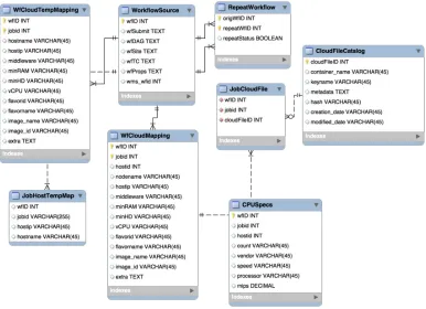
J. ReCAP Database Schema
A relational database schema has been designed that assists in storing workflow descriptions and their configuration files, workflow job-to-Cloud resource mappings and files metadata (consumed or produced data by the workflow jobs) stored on the Cloud. This information later helps in retrieving CAP information and also helps in answering Cloud-aware provenance queries and comparing workflow outputs. Following paragraphs describe the key tables of the schema shown in Figure 9.
In order to preserve the original workflow and its associated configuration files, theWorkflowSource table is used. It stores the workflow representation in the DAX format. Since the implemented prototype is based on Pegasus, this table also stores pegasus specific files such as Transformation Catalog (TC) inwfTC, infrastructure information inwfSite. The wfDAGcolumn stores the workflow representation described in a DAG format. This is an abstract workflow which will be submitted through Pegasus for execution. The wfSitecolumn stores the information related to the execution site and its storage elements. This information specifies the storage locations and paths to be used for reading and writing data during the workflow execution. The wfTC column stores information about the executables which are to be used for workflow jobs. A user can also provide configuration properties to Pegasus that affects the way Pegasus plans, schedules and stores workflows. This set of properties is stored in the wfProps column. Each workflow is assigned a unique ID by Pegasus and also in the ReCAP database, thus a mapping between these two IDs are required. The wfID is the ID assigned to a workflow execution by ReCAP and the
wms wfid is the unique ID assigned to a workflow by the workflow management system such as Pegasus. The wms wfid is
essential to record because it is used in retrieving workflow provenance from the Pegasus. Since the prototype is designed using the Pegasus WMS, this table contains a few Pegasus specific entries. However, the same concepts can also be applied when used with other similar workflow management systems.
Fig. 9:ReCAP relational database schema
In order to store the job-to-Cloud resource mapping and to record Cloud-aware provenance information, theWfCloudMapping
table is used. This table stores the mapping between workflow jobs and the configurations of the Cloud resources used for their execution. In order to specify the resource flavour, that provides the resource hardware configurations,flavornameandflavorid
are stored. However, this information can be customised or new entries can be added by the Cloud Provider. For instance, Amazon EC2 provides an extensive list6 of instance types with customized values. On the other hand, Openstack middleware used in Open Science Data Cloud (OSDC) provides a limited set of instance types. Therefore, the individual parameters i.e.
minRAM,minHD,minCPU of a Cloud resource are also stored.
In order to tackle the dynamic resource scenario on the Cloud, theWfCloudTempMapping table stores temporary mapping information which is then moved to the WfCloudMapping table once a workflow execution has finished. There is another table, JobHostTempMap, that stores temporary job and its execution host mapping. This table is used in the SNoHi mapping approach. In order to store more detailed information about the CPU, the CPUSpecs table is used. Although, the existing Cloud providers and their offerings do not allow a user to request a resource with such resource parameters, the impact of CPU performance still cannot be ignored especially for compute-intensive jobs. Moreover, this information is also helpful when sharing experimental setup and results with the peers. This is why this information is captured and stored as part of the Cloud-aware provenance.
As discussed earlier, the data files are stored on the Cloud, this is why it is important to keep track of file locations and metadata on the Cloud. To achieve this, theJobCloudFileandCloudFileCatalogtables are conceived. TheJobCloudFile table stores the mapping between workflow jobs and its produced/consumed files on the Cloud. The CloudFileCatalog provides detailed information about a file stored on the Cloud. This information includes the location of the file, specified by the
container nameandkeyname, MD5hashof the file contents, additionalmetadatastored along with the file,creation dateand
modified date.
In order to tackle the dynamic resource scenario on the Cloud , the WfCloudTempMapping table is used. This table stores temporary mapping information which is then moved to the WfCloudMappingtable once a workflow execution has finished. There is another table, JobHostTempMap, that stores temporary job and its execution host mapping. In order to store more detailed information about the CPU, theCPUSpecstable is used. Although, the existing Cloud providers and their offerings do not allow a user to request a resource with such resource parameters, the impact of CPU performance still cannot be ignored especially for compute-intensive jobs. Moreover, this information is also helpful when sharing experimental setup and results with the peers. This is why this information is captured and stored as part of the Cloud-aware provenance.
As discussed earlier, the data files are stored on the Cloud, this is why it is important to keep track of file locations and metadata on the Cloud. To achieve this, theJobCloudFileandCloudFileCatalogtables are conceived. TheJobCloudFile table
stores the mapping between workflow jobs and its produced/consumed files on the Cloud. The CloudFileCatalog provides detailed information about a file stored on the Cloud. This information includes the location of the file, specified by the
container name andkeyname, MD5 hash of the file contents, additional metadata stored along with the file, creation date
andmodified date. By using this information, it is not only able to provide information about the file, but also can be helpful
in comparing the file contents produced from workflow repeated executions to verify a workflow result. This also helps in identifying if a file is changed over time, which, however, is not the focus of this research study. For instance, a file created by a job will have the same creation and modification time or even no modification time. However, if a file is modified or tampered with somehow, the modification date will be updated. By comparing the latest dates with the already stored information, one can deduce if the file contents are changed.
IV. PROVENANCECOMPARISON
Comparing provenance has been used as a mechanism to determine reproducibility. Since scientific workflows typically model a dataflow with a structure resembling a directed acyclic graph (DAG), the provenance comparison approaches measure similarity between two given provenance traces using graphs [10]. This section discusses the proposed graph model and mechanism used to compare the provenance information of two workflows i.e. the original and the reproduced workflows to measure how much a reproduced workflow resembles the original execution. This mechanism is used in the Comparator component of ReCAP. In order to achieve this, two provenance graphs are compared at three levels, which are presented as follows:
• Workflow Graph Structure Comparison: Only graph structures are compared for two given workflows executions (original and reproduced) to determine their structural similarity.
• Workflow Infrastructure Comparison: The provisioned Cloud resources to execute workflow jobs are compared for two given workflow executions. This comparison ensures whether the used infrastructure is similar or not.
• Workflow Output Comparison: The data produced by workflow jobs are compared to ensure that the output produced as a result of workflow execution is similar.
A. Workflow Graph Structure Comparison
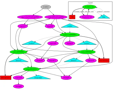
Structure-based approaches to measure workflow similarity perform various comparisons on the two workflow graphs [22]. These comparisons can be of many forms. It could just be based on DAG structure i.e. comparing vertices and edges, and it could also include retrospective provenance data such as runtime information and execution parameters [10]. Since ReCAP also captures infrastructure information, it should also be accommodated in the graph and used in graph comparison. Before discussing the provenance graph comparison, the following paragraphs first discuss the graph representation used in this work. The workflow provenance can be represented as G=< V, E >, whereG is a workflow provenance graph and it consists of a set of vertices V and a set of edgesE. In this graph representation, both vertices and edges are labelled.V is a set of vertices that can be defined as V =N[H[F (where N is job nodes during workflow execution andH represents virtual machines where the job execution took place and F is the files/data produced or consumed during workflow execution). The job nodes also include the augmented jobs created at runtime by the workflow management system to support data stage-in, stage-out or clean-up operations. A sample graph representation is shown in Figure 10. E is a set of edges and it is defined as
E=Etask[Eexec[Ein[Eout
whereEtask represents the task edge between workflow jobs produced and executed by the Pegasus.Eexec represents the edges between jobs and the hosts H on which the workflow job was executed. Ein represents the edges between input data and a job consuming the data.Eout represents the edges between output data and a job producing the data. In this graph, only connected nodes with at least one of the above mentioned edges are considered.
The following are the representation of different edges between two given nodes in the generated provenance graph G.
Etask(i,j)=Ni, Etask, Nj
Eexec(i,h)=Ni, Eexec, Hh
Ein(i,f)=Ni, Ein, Ff
Eout(i,f)=Ni, Eout, Ff
Based on this graph description, two provenance comparison algorithms have been devised. The first algorithm,Provenance
Graph Boolean Comparison (see Section IV-A1), performs the provenance graph comparison and determines the similarity
������
�������
����������������������� ���������������������
��������� ���������
�������������������
��������������
���������������� ����������������
���������� ���������
��������� ���������
������������
������������ ���������� ����������� ���������
��������� ����������
��������� ��������� ����������
��������
���������
�����������
������������� ��������
�� �����������
[image:10.612.119.492.68.366.2]���� �������� �������� ��������
Fig. 10:An example provenance graph generated from the captured workflow execution provenance
graph comparison algorithms, it is assumed that the graph vertices labels remain same for two same workflows. In case a given workflow is same (in terms of contents of executables, and file inputs and outputs) as was in previous workflow execution but its vertices’ names are changed, the algorithm will treat these vertices as different entities and thus no common vertices will be found between these two workflow graphs. This will result in graph structure mismatch.
1) Provenance Graph Boolean Comparison: The provenance graph Boolean comparison algorithm includes the following
criteria.
• Graph Size
The graph size refers to counting the number of nodes/vertices. This similarity check is known as the isomorphic property of a graph. In this case, the graph size is counting the nodes including jobs, hosts, and data file along with the edge counts. Both given graphs should have same count.
• Workflow Comparison with edges
It is also important to compare the edges in the given two workflows. As discussed earlier, edges establish a relation between two vertices in a graph. Since the graph representation, shown in Figure 10, uses four different edges between three different nodes, it is important to compare all these different edges in both given provenance graphs. For two provenance graphs to be determined as same, they both should have same nodes and same relationship i.e. edges between them. Following criteria is used to determine that the edges in both the given workflow provenance graphs are same.
8Edgestask2W Fo, n
X
i=1
Etaski=8Edgestask2W Fr, n
X
i=1
Etaski
8Edgesexec2W Fo, n
X
i=1
Eexeci=8Edgesexec2W Fr, n
X
i=1
Eexeci
8Edgesin2W Fo, n
X
i=1
Eini=8Edgesin2W Fr, n
X
i=1
Eini
8Edgesout2W Fo, n
X
i=1
Eouti=8Edgesin2W Fr, n
X
i=1
Eouti
otherwise a difference is returned (see lines 2 and 3). After this, the graph traversal starts from the root node. For traversing a graph, a recursive function (termed the CompareNode) is implemented that traverses each graph vertex until no further child vertices are found. For each graph vertex, it collects its successors (i.e. children) and collects all edges for every node (lines 10-17). Since there are four types of edges, these edges are passed to a filtering function (termed the ProcessEdges) to determine the edge type. Each edge is added to an edge collection of that type. Later these edge collections (taskEdge on line 25 and consumeEdges on 27, etc.) are compared for both graphs and it is determined whether both graphs have same edges or not. For job-to-VM edge (executed on edge), VM configurations i.e. hostinfo, including the RAM, CPUs, HD and flavour and OS image, are stored in the edge collection (see line 31). It is important to note that the VM configurations are considered when processing the graph node representing the VM. Therefore, name of the virtual machine is not significant for this algorithm.
Algorithm 1 Graph Structure Comparison Algorithm Require: P ROVo:Original workflow provenance graph.
P ROVr:Reproduced workflow provenance graph.
1: procedurePROVGRAPHSTRUCTCOMP(P ROVo, P ROVr)
2: ifP ROVo.nodes6=P ROVr.nodes then
3: return the differentP ROVo.nodes P ROVr.nodes
4: Rooto P ROVo.root
5: Rootr P ROVr.root
6: COMPARENODES(P ROVo, P ROVr, Rooto, Rootr) .Traverse the graphs
7: procedureCOMPARENODES(P ROVo, P ROVr, n, ´n)
8: So P ROVosuccessors(n)
9: Sr P ROVr.successors(´n)
10: iflen(So) =len(Sr)then
11: for allc inSo and ´c inSr do
12: E P ROVo.edges(c)
13: ´E P ROVr.edges(´c)
14: PROCESSEDGES(E) 15: PROCESSEDGES(E´)
16: COMPARENODES(P ROVo, P ROVr, c, ´c) .Recursive call
17: procedurePROCESSEDGES(edges) 18: for alle inedgesdo
19: ife.type=taskthen
20: taskEdges e
21: else ife.type=consumesthen
22: consumeEdges e
23: else ife.type=producesthen
24: producesEdges e
25: else ife.type=executed onthen
26: hostEdges hostinf o
2) Provenance Graph Numerical Comparison: Algorithm 1 can perform a graph structure comparison and provide an
answer:TrueorFalse. However, it cannot inform the extent of similarity or dissimilarity between two given provenance traces. To achieve a deterministic or quantifiable answer for provenance graph structure comparison, the following graph comparison model is proposed.
Let there be two provenance graphs P ROVo and P ROVr representing original workflow execution and the reproduced workflow execution respectively. Let Vo be the number of vertices and Eo be the number of edges between the vertices of the P ROVo graph. Let Vr be the number of vertices and Er be the number of edges between the vertices of the P ROVr graph. Since P ROVr is to be compared against P ROVo, it is imperative to determine the number of common vertices and common edges between these two graphs. Let CV be the common number of vertices and CE be the common number of edges between two graphs. In order to calculate the CE, consider only those edges whose vertices that2CV. As the graph structure is composed of vertices and edges, the following rule can be used to determine the numeric value for a provenance graph structure.
S=V +E (1)
In case of the original workflow, the structure can be determined in terms of its number of nodes and number of edges as given below.
whereVo andEorepresent the number of vertices and edges of the base graph respectively. Since we also calculate a numeric value for common edges and vertices, the value for common graph structure (CS) can be calculated as follows:
CS=CV +CE (3)
The list of common vertices is identified by comparing the labels of vertices in both the provenance graphs. The vertex label available in both the provided graphs is treated as a common vertex. In case of a vertex representing a virtual machine, its label is generated dynamically by concatenating the resource configuration information of the used virtual machine. The number of the found common vertices is used as a numeric value forCV. Once the list of common vertices is extracted, it is iterated for both the graphs and their directed edges, which include their connecting vertices’ information, are retrieved from both graphs. Since our provenance graph is a directed graph, the edge A-¿B != A¡-B because edge direction between A and B is different. Once the edges of all the common vertices are obtained from both the graphs, the intersection of the edges is obtained. This intersection is treated as common edges CE based on common vertices in the given two graphs. With these values known, the structural similarity (SS) of both the given provenance graphs can be determined as follows:
SS=CS/So (4)
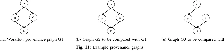
This structural similarity is calculated as a ratio to the given base graph. Since the reproduced workflow is compared against the original execution, So is used as a base graph. In order to understand this model, assume the sample provenance graphs shown in Figure 11 can be used. The graph G1 represents a provenance trace of original workflow execution. Let us assume that the other two graphs i.e. G2 and G3 are generated from the provenance information of the reproduced workflow. As can be seen all these graphs are slightly different to each other. If we apply the Algorithm 1 to compare G1 and G2, or G1 and G3 graphs, it will produce False on the comparison test. As discussed before, we can determine the quantifiable value for structural similarity with this numeric model.
Based on the base graph G1 of the original execution, the count for Vo is 4 andEo is also 4. Therefore, the So value is 8. While comparing the graph G2 with G1, the common vertices are 3 because vertex X does not exist in graph G1. This influences the common edges count, which is 2 in this case, as well because the edges between A!X and X!D cannot be accommodated according to the model because these edges have one vertex that does not belong to CV. The SS value for graph G1 and G2 will be 0.625 which is 62.5% similarity. Similarly, for graph G3, the structural similarity (SS) with G1 is 0.875 which is 87.5 % similarity because it only misses one edge from A to C.
A
B C
D
(a)Original Workflow provenance graph G1
A
B X
D
(b)Graph G2 to be compared with G1
A
B C
D
[image:12.612.83.538.411.519.2](c)Graph G3 to be compared with G1 Fig. 11:Example provenance graphs
The above calculatedSS value will produce asymmetric results if the base graph is changed. For instance, if the base graph is G3, and G1 is compared with G3, the calculated value will be different from SS(G1, G3). With the above calculation, SS(G1, G3) is 87.5%, however SS(G3, G1) becomes 100%, which is an incorrect result. To avoid this situation, the ratios of the common vertices to the total vertices and the common edges to the total edges from both graphs should be calculated. In order to do this, the following equation is used. This equation aids in eliminating the asymmetric result which was present in the previous calculation. With this new equation, the values for SS(G1, G3) and SS(G3, G1) are both 92%.
SS= CV
Vo+Vr + CE
Eo+Er (5)
B. Workflow Output Comparison
Algorithm 2 Compare Workflow Outputs Algorithm Require: srcW f ID:Source Workflow ID.
destW f ID:Destination Workflow ID
1: procedureCOMPAREWORKFLOWOUTPUTS(srcW f ID,destW f ID) 2: srcWorkflowJobs GETWORKFLOWJOBS(srcW f ID)
3: destWorkflowJobs GETWORKFLOWJOBS(destW f ID) 4: FileCounter 0
5: ComparisonCounter 0
6: for alljobfiles2srcW orkf lowJobsdo 7: src container jobfiles.container name 8: src filename jobfiles.file name
9: dest container destWorkflowJobs[jobfiles.jobname] 10: dest filename destWorkflowJobs[jobname].file name
11: src cloud file GETCLOUDFILE(src container src filename )
12: dest cloud file GETCLOUDFILE(dest container dest filename )
13: FileCounter FileCounter + 1
14: ifsrc cloud f ile.hash=dest cloud f ile.hashthen
15: ComparisonCounter ComparisonCounter + 1
16: ifF ileCounter=ComparisonCounterthen
17: return True 18: return False
Algorithm 2 operates over the two given workflows identified by srcWfID and destWfID, and compares their outputs. It first retrieves the list of jobs and their produced output files from the Provenance Store for each given workflow. It then iterates over the files and compares the source file, belonging to srcWfID, with the destination file, belonging to destWfID. Since the files are stored on the Cloud, the algorithm retrieves the files from the Cloud (see lines 11 and 12). Cloud storage services such as OpenStack Swift7 and Amazon Storage Store (S3)8 use the concept of a bucket or a container to store a file. This is why src container and dest container along with src f ilename and dest f ilename are given in the GetCloudFile function to identify a specific file in the Cloud. The algorithm then compares the hash value of both files and increments the
ComparisonCounter. If all the files in both workflows are the same, theComparisonCountershould be equal to theFileCounter,
which counts the number of files produced by a workflow. Thus, it confirms that the workflows are repeated successfully. Otherwise, the algorithm returns false if both these counters are not equal. This means that the two given workflows have not produced the same outputs.
V. RESULTS ANDANALYSIS
In order to evaluate the affect of Cloud configuration on the workflow execution and also to evaluate the proposed comparison approaches in ReCAP, three types of workflows from different scientific domains have been used. These workflows are named; 1) Montage9 workflow from astronomy domain, 2) ReconAll10 workflow from neuroscience domain and 3) Wordcount, a sample workflow.
The Montage workflow uses the components of Montage, a widely mentioned astronomy application to build mosaics of the sky by stitching together multiple input images [32]. The Montage workflow used in the experiment contains 35 jobs and required 8 input image files. This workflow produces 4 output files including one mosaic image file in JPEG format. The ReconAll workflow (also called pipeline in N4U) is used in N4U and neuGRID11 projects to reconstruct the given MRI scan image of a subject. This workflow has only one job that executes recon-all command on the given input neuro-image. The sample workflow i.e. Wordcount is designed for controlled experiments and it exhibits the same characteristics i.e. split and merge jobs found in complex scientific workflows such as Montage. It is composed of four jobs and takes one text file input. The first job (the Split job) took a text file and split it into two files of almost equal length. Later, two jobs (the Analysis jobs) were applied; each of these takes one file as input, and then calculates the number of words in the given file. The fourth job (the Merge job) took the outputs of earlier analysis jobs and calculated the final result i.e. total number of words in both files. As discussed in Section IV, the workflow reproducibility is determined by comparing the provenance graphs of both original and reproduced workflow. This comparison includes graph structural comparison, infrastructure comparison and output comparison. For these tests, the provenance traces of original workflows and their reproduced counterparts were provided to the comparison algorithms and their results are analysed in Sections V-B and V-C. Another purpose of this experiment was
7http://swift.openstack.org 8https://aws.amazon.com/s3/ 9http://montage.ipac.caltech.edu/
TABLE II:Cloud-aware Provenance captured for the given workflows with wfIDs 132 and 134
WfID nodename Flavour Image name Image Id
132 uwe-vm3 2
condorvm-quantal-snapshot 269cfb39-7882-4067-bf20-b3350a4b1b05 132 uwe-vm4 2
condorvm-quantal-snapshot 269cfb39-7882-4067-bf20-b3350a4b1b05 134 uwe-vm4-rep 2
condorvm-quantal-snapshot 269cfb39-7882-4067-bf20-b3350a4b1b05 134 uwe-vm3-rep 2
condorvm-quantal-snapshot 269cfb39-7882-4067-bf20-b3350a4b1b05 Resource specifications: RAM = 2048 MB, Hard Disk (HD) = 20 GB, vCPU = 1
to verify that the comparison approaches perform according to the theoretical understanding that was presented in previous sections.
A. Infrastructure Re-provisioning
First of all, it is important to assess the capability of ReCAP in capturing Cloud-aware provenance and then using it to re-provision resources on the Cloud for workflow reproducibility (discussed in [11]). In order to verify this, aforementioned workflows are submitted and their provenance data are captured by ReCAP. The purpose of this experiment is also to evaluate the ability of ReCAP to handle different types of workflows with varying number of jobs and to re-provision resource on the Cloud using the Cloud-aware provenance information. Following subsections provide the detailed analysis of the results.
1) Using Wordcount Workflow: The Wordcount workflow was executed using the Pegasus. The original execution of this
workflow was assigned an ID 132. Table II shows the interlinked provenance mapping (both the workflow provenance and the Cloud infrastructure information), in the ReCAP database for this workflow. The collected information includes the flavour and image (image name and Image id) configuration parameters. TheImage Iduniquely identifies an OS image hosted on the Cloud and this image contains all the software or libraries used during the job execution. This workflow is then resubmitted with ID 134 by re-provisioning the resources on the Cloud using the Cloud-aware provenance, and its provenance is captured as shown in Table II. The execution times of both workflows were 313.20 and 312.4 seconds respectively. The captured provenance of the reproduced workflow shows that the system was able to re-provision the similar execution resources on the Cloud.
2) Using Montage Workflow: The original execution of this workflow was assigned an ID 533 and the reproduced workflow
was assigned an ID 534. Following Table III shows the Cloud infrastructure provisioned for the execution of workflows 533 and 534 respectively. The workflow execution times for the both workflows were 285 and 281 seconds respectively. This shows that the Montage workflow execution was reproduced with a similar execution performance on the same Cloud resources provisioned by ReCAP.
TABLE III:Infrastructure detail captured for the Montage workflow (wfID=533) and reproduced workflow (wfID=534) using ReCAP
WfID nodename Flavour Image name Image Id
533 uwe-vm3 2 wf peg repeat f102960c-557c-4253-8277-2df5ffe3c169 533 mon1 2
montage-condor-setup 2d9787e4-b0e9-4802-bf4f-4a0c868bb11a 534 mon1-rep 2
montage-condor-setup 2d9787e4-b0e9-4802-bf4f-4a0c868bb11a 534 uwe-vm3-rep 2 wf peg repeat
f102960c-557c-4253-8277-2df5ffe3c169 Resource specifications: RAM = 2048 MB, Hard Disk (HD) = 20 GB, vCPU = 1
3) Using ReconAll Workflow: The ReconAll workflow consists of one job script only and requires one input file. Its execution
requires one virtual machine on the Cloud. The original execution of this workflow was assigned ID 545 and its captured Cloud-aware provenance using ReCAP is shown in Table IV. The same workflow was re-executed using ReCAP and its provenance information is recaptured. The reproduced workflow execution was assigned an ID 547. The recaptured provenance of the reproduced workflow 547 is show in Table IV. These tables show that ReCAP was able to capture the Cloud infrastructure information in the original execution and was also able to re-provision the resource with the same configurations on the Cloud.
B. Structure Analysis
[image:14.612.177.431.500.602.2]TABLE IV:Infrastructure detail captured for the ReconAll workflow (wfID=545) and reproduced workflow (wfID=547) using ReCAP
WfID nodename Flavour Image name Image Id
545 freesurf 2 freesurf-condor 2ee3c500-61b5-4592-8d54-e572536b5df1 547 freesurf-rep 2 freesurf-condor
2ee3c500-61b5-4592-8d54-e572536b5df1 Resource specifications: RAM = 2048 MB, Hard Disk (HD) = 20 GB, vCPUs = 1
IV-A). These graphs are then evaluated using the proposed comparison approaches i.e. Boolean andNumerical to determine the degree of similarity between them. For the case of the Wordcount workflow, both workflows i.e. 132 and 134 have been executed by provisioning the same virtual machines on the Cloud. The Boolean Comparison produces T rue because both graphs contain equal numbers of nodes (i.e. job, virtual machines, files) and all the edges between them are also the same. The structural similarity between the two graphs calculated by the Numerical Comparison algorithm is also 100%. This shows that both graphs are the same and the jobs were executed on the same virtual machines. The infrastructure analysis on both the provenance traces shows that two virtual machines with same configurations were provisioned to execute workflow 134.
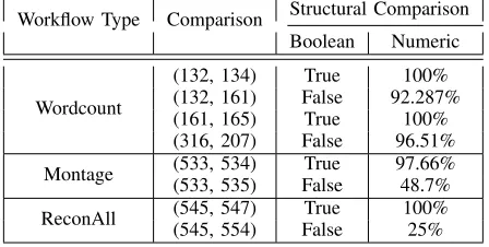
However, it is possible that the structural analysis of two given provenance graphs of same workflow producesF alseor < 100% similarity (see Table V). This can be caused by multiple reasons. One of them is a change in the workflow description. The other pertinent reason is a change in the infrastructure information i.e. CAP in the collected provenance. This change in CAP can appear by provisioning virtual machines with different configurations (see comparison between 132 and 161 in Section V-C). Another reason for this change is because of the job scheduling mechanism used by WMS. Since WMS does not incorporate the CAP information in job scheduling decision, it is possible that a job may be submitted to a different machine. These behaviours can be seen in Table V.
TABLE V:Provenance structural analysis of workflows (132, 134), (132, 161), (161, 165), (316, 207)
Workflow Type Comparison Structural Comparison Boolean Numeric
(132, 134) True 100%
(132, 161) False 92.287%
(161, 165) True 100%
Wordcount
(316, 207) False 96.51%
(533, 534) True 97.66%
Montage (533, 535) False 48.7%
(545, 547) True 100%
ReconAll (545, 554) False 25%
C. Infrastructure Analysis
This section discusses the infrastructure information captured by the ReCAP framework during workflow execution. By analysing the infrastructure details, the comparison provided in Table V can be better understood. For this analysis, four workflow executions with workflow ID 132, 161, 316 and 207 are selected because their structural analysis is False and below 100%. The infrastructure detail of workflow 165 is also used to determine the reason behind 100% structural similarity. Table VI shows the infrastructure information captured for these workflows.
As it can be seen that the configurations for the provisioned virtual machines for workflows 161 and 165, and 316 and 207 are same, however the structural similarity is different for (161, 165) and (316, 207) comparisons. As discussed in previous Section V-B, one of the reasons for this difference is the job scheduling. To verify this, the following tables VII, VIII, IX and X show the job-to-Cloud resource mapping for each job of workflows 161, 165, 316 and 207 respectively.
From the tables VII and VIII, it is clear that all jobs of workflow 165 have been executed on the same virtual machines as was the case with the jobs of workflow 161. Due to this reason, there is no edge difference found between their provenance graphs and thus the resultant structural similarity was 100%. However, this was not the case with workflows 316 and 207 as shown in the Tables IX and X. The differences between jobs scheduled to different machines are highlighted in red.
Table VI shows that the configurations of the provisioned resources are the same. However, there is a change in the job-to-Cloud resource mapping. Many of the virtual machine configurations such as are same for the jobs of both workflows 316 and 207 (see Tables IX and X). However, the OS image i.e. image name and image id columns are different. For example, the job analysis ID1000002of workflow 207 was executed on OS image uwe-condor-snapshot, however the same job of workflow
[image:15.612.193.417.355.468.2]TABLE VI:Infrastructure details captured for the workflows using ReCAP
WfID nodename Flavour Image name Image Id
132 uwe-vm3 2 condorvm-quantal-snapshot 269cfb39-7882-4067-bf20-b3350a4b1b05 132 uwe-vm4 2 condorvm-quantal-snapshot 269cfb39-7882-4067-bf20-b3350a4b1b05 161 uwe-vm4 2 uwe-condor-snapshot 4d05e308-b46d-4a9e-8a29-237bebf11161 161 uwe-vm3 2 uwe-condor-vm ca16f4a2-dba3-44c0-a3b5-72267094ff40 161 uwe-vm4 2 uwe-condor-snapshot 4d05e308-b46d-4a9e-8a29-237bebf11161 161 uwe-vm3 2 uwe-condor-vm ca16f4a2-dba3-44c0-a3b5-72267094ff40 165 uwe-vm3-rep 2 uwe-condor-vm ca16f4a2-dba3-44c0-a3b5-72267094ff40 165 uwe-vm4-rep 2 uwe-condor-snapshot 4d05e308-b46d-4a9e-8a29-237bebf11161 316 uwe-vm4 2 uwe-condor-snapshot 4d05e308-b46d-4a9e-8a29-237bebf11161 316 uwe-vm3 2 uwe-condor-vm ca16f4a2-dba3-44c0-a3b5-72267094ff40 207 uwe-vm3-rep 2 uwe-condor-vm ca16f4a2-dba3-44c0-a3b5-72267094ff40 207 uwe-vm4-rep 2 uwe-condor-snapshot 4d05e308-b46d-4a9e-8a29-237bebf11161
Resource specifications: RAM = 2048 MB, Hard Disk (HD) = 20 GB, vCPU = 1 TABLE VII:Virtual machines used by the jobs of workflow 161
WfID Job Name Machine Image name Image Id
161 analyse
ID0000002 uwe-vm4 uwe-condor-snapshot 4d05e308-b46d-4a9e-8a29-237bebf11161 161 analyse
ID0000003 uwe-vm3 uwe-condor-vm ca16f4a2-dba3-44c0-a3b5-72267094ff40 161 preprocess
ID0000001 uwe-vm4 uwe-condor-snapshot 4d05e308-b46d-4a9e-8a29-237bebf11161 161 merge
ID0000004 uwe-vm3 uwe-condor-vm ca16f4a2-dba3-44c0-a3b5-72267094ff40 Resource specifications:Flavour=2,RAM=2048 MB, Hard Disk(HD)=20 GB, vCPU=1
two provenance graphs. This also shows that job scheduling can impact the structural comparison even if the re-provisioned infrastructure is same. Since OS image provides a complete software stack including libraries and binaries, a change in OS image can possibly result into a failed or ill-performed job execution. [33] has also raised the same concern. Based on this analysis, it can be proposed that job scheduling algorithm should also incorporate the Cloud-aware provenance information.
TABLE VIII: Virtual machines used by the jobs of workflow 165
WfID Job Name Machine Image name Image Id
165 analyse
ID0000002 uwe-vm4 uwe-condor-snapshot 4d05e308-b46d-4a9e-8a29-237bebf11161 165 analyse
ID0000003 uwe-vm3 uwe-condor-vm ca16f4a2-dba3-44c0-a3b5-72267094ff40 165 preprocess
ID0000001 uwe-vm4 uwe-condor-snapshot 4d05e308-b46d-4a9e-8a29-237bebf11161 165 merge
[image:16.612.182.431.601.694.2]ID0000004 uwe-vm3 uwe-condor-vm ca16f4a2-dba3-44c0-a3b5-72267094ff40 Resource specifications: RAM = 2048 MB, Hard Disk (HD) = 20 GB, vCPU = 1 TABLE IX:Virtual machines used by the jobs of workflow 316
WfID Job Name Machine Image name Image Id
316 analyse
ID0000002 uwe-vm3 uwe-condor-vm ca16f4a2-dba3-44c0-a3b5-72267094ff40 316 analyse
ID0000003 uwe-vm4 uwe-condor-snapshot 4d05e308-b46d-4a9e-8a29-237bebf11161 316 preprocess
ID0000001 uwe-vm3 uwe-condor-vm ca16f4a2-dba3-44c0-a3b5-72267094ff40 316 merge
TABLE X:Virtual machines used by the jobs of workflow 207. Rows in red highlights the changes due to scheduling
WfID Job Name Machine Flavour Image name Image Id
207 analyse ID0000002 uwe-vm4 2 uwe-condor-snapshot 4d05e308-b46d-4a9e-8a29-237bebf11161 207 analyse ID0000003 uwe-vm3 2 uwe-condor-vm ca16f4a2-dba3-44c0-a3b5-72267094ff40 207 preprocess ID0000001 uwe-vm4 2 uwe-condor-snapshot 4d05e308-b46d-4a9e-8a29-237bebf11161 207 merge ID0000004 uwe-vm3 2 uwe-condor-vm ca16f4a2-dba3-44c0-a3b5-72267094ff40
Resource specifications: RAM = 2048 MB, Hard Disk (HD) = 20 GB, vCPUs = 1
D. Workflow Output Analysis
The other aspect in evaluating the workflow reproducibility is to verify the outputs produced by both workflows. This has been achieved using the algorithm presented in Section IV-B. Four jobs in both the given Wordcount workflows i.e. 132 and 134 produce the same number of output files (see Table XI). The Split job produces two output files i.e. wordlist1 and
wordlist2. Two analysis jobs, Analysis1 andAnalysis2, consume the wordlist1 andwordlist2files, and produce the analysis1
and analysis2 files respectively. The merge job consumes the analysis1 and analysis2 files and produces the merge output
[image:17.612.128.484.348.481.2]file. The hash values of these files are shown in the MD5 Hash column of the Table XI; of here both given workflows are compared with each other. For instance, the hash value of wordlist1produced by the Split job of workflow 134 is compared with the hash value of wordlist1produced by the Split job of workflow 132. If both the hash values are same, the algorithm will return true. This process is repeated for all the files produced by both workflows. The algorithm confirms the verification of workflow outputs if the corresponding files in both workflows have the same hash values. Otherwise, the verification process fails, which means that both the workflows have not produced the same output. Consequently, this means that the workflow result could not be reproduced.
TABLE XI:Comparing outputs produced by workflows 132 (original workflow) and 134 (reproduced workflow)
Job WF
ID Cloud Container Name File Name MD5 Hash
132 wfoutputWordcount wordlist1 0d934584cbc124eed93c4464ab178a5d 134 wfoutputWordcount wordlist1 0d934584cbc124eed93c4464ab178a5d 132 wfoutputWordcount wordlist2 1bc6ffead85bd62b5a7a1be1dc672006 Split
134 wfoutputWordcount wordlist2 1bc6ffead85bd62b5a7a1be1dc672006 132 wfoutputWordcount analysis1 494f24e426dba5cc1ce9a132d50ccbda Analysis1
134 wfoutputWordcount analysis1 494f24e426dba5cc1ce9a132d50ccbda 132 wfoutputWordcount analysis2 127e8dbd6beffdd2e9dfed79d46e1ebc Analysis2
134 wfoutputWordcount analysis2 127e8dbd6beffdd2e9dfed79d46e1ebc 132 wfoutputWordcount merge output d0bd408843b90e36eb8126b397c6efed Merge
134 wfoutputWordcount merge output d0bd408843b90e36eb8126b397c6efed
[image:17.612.90.518.575.689.2]Similar is the case with the Montage workflow. This workflow produces and registers four output files. Two files are produced by the mAdd job, one file is produced by the mShrink job and the final output (mosaic) file is produced by the mJPEG job (see Table XII). The other intermediary files produced and consumed during the workflow execution are not registered as output files. Table XII shows the outputs produced by the workflow 533 and 534. Seeing the MD5 Hash column, it can be deduced that all files produced by these jobs are identical in both workflow executions.
TABLE XII:Comparing outputs produced by Montage workflows 533 (original workflow) and 534 (reproduced workflow)
Job WF
ID CloudName Container File Name MD5 Hash
533 wfoutputMontage533 mosaic 20150713 012457 17045.fits d7e28c00577c6a5e145bf1d478be600b 534 wfoutputMontage534 mosaic 20150713 012457 17045.fits d7e28c00577c6a5e145bf1d478be600b 533 wfoutputMontage533 mosaic 20150713 012457 17045 area.fits 11da235545a86d08a3e00ff2c84a31bd mAdd
534 wfoutputMontage534 mosaic 20150713 012457 17045 area.fits 11da235545a86d08a3e00ff2c84a31bd 533 wfoutputMontage533 shrunken 20150713 012457 17045.fits 7c81dc2d39fa1bcb2ba829ff8e650559 mShrink
534 wfoutputMontage534 shrunken 20150713 012457 17045.fits 7c81dc2d39fa1bcb2ba829ff8e650559 533 wfoutputMontage533 shrunken 20150713 012457 17045.jpg 2e30b4094651e6e1a82d12eb83be1372 mJPEG
534 wfoutputMontage534 shrunken 20150713 012457 17045.jpg 2e30b4094651e6e1a82d12eb83be1372
TABLE XIII:Showing timestamp in a log file (mri convert) produced by ReconAll
ReconAll WF 545 ReconAll WF 547 (reproduced)
....mri_convert -all-info .... TimeStamp:2015 /09/28-04:16:28-GMT
.... User:ubuntu Machine:newfree. novalocal
....mri_convert -all-info .... TimeStamp:2015 /09/29-05:11:24-GMT
.... User:ubuntu Machine:newfree. novalocal
contained the machine information which could also be different especially if machine name or IP information is logged. Some log file snippets are provided in Table XIII. For instance, the log file of job mri convertproduced by workflow 545 generated a different hash as compared to the same file produced by workflow 547 because they had different timestamps. Due to this reason, the MD5 applied on the files produced different results for different workflow executions. A thorough analysis of the produced output files revealed that the main files related to thickness, area and volume of the given brain-scan produced the same hash values in the original and also in the reproduced workflow. This specific result leads to a conclusion that MD5 approach for comparing workflow outputs works fine in cases when jobs do not include timestamps or machine information in the produced output. Otherwise this approach cannot work. Similar concerns in comparing outputs have been raised in [20]. In order to overcome this issue in workflow output comparison, the workflow or application developer e.g. the ReconAll developer in the case of ReconAll workflow, should provide a comparator tool. This tool can then be integrated into the output comparison algorithm used for comparing the outputs for that particular workflow.
E. Discussion
In this section, a detailed analysis of the provenance graph comparison is presented. In doing so, three different aspects of the provenance graph are evaluated and analysed. The structural comparison between two provenance graphs were performed by employing the two proposed comparison algorithms i.e. the Boolean Comparison and Numerical Comparison. From the
BooleanComparison, one can access whether the provided graphs are identical or not. However, it does not provide information
about the degree of similarity. For this, the Numerical comparison algorithm was applied. From the result (see Table V), it was found that the provenance graphs might not be identical despite the same execution infrastructure used for workflow re-execution. A detailed analysis of the result showed that it was due to two main reasons. First reason was that a change in the workflow itself could affect the graph comparison. The second reason was that a change in the job-to-Cloud resource mapping can also affect the graph structure comparison. From the detailed analysis of the infrastructure information i.e. job-to-Cloud resource mapping, the second case was found when comparing workflow 316 with 207. Tables IX and X showed that jobs of workflow 207 were executed on different machines when compared against the jobs resource mapping of workflow 316. As discussed earlier, this was due to the job scheduling algorithm in the workflow management system, which is outside the scope of this research work. Since the job scheduling algorithm does not utilize the Cloud-aware provenance information, it schedules job to any of the available resource according to its scheduling policy.
Besides comparing the workflow execution time to determine workflow reproducibility, workflow output comparison has also been identified as a means to verify the reproducibility of a workflow execution. Since all workflows in modern scientific experiments are data oriented and they consumed and produced data, this comparison provides a mechanism to verify the produced outputs. The output comparison of the Wordcount workflows showed that the outputs were successfully produced in reproduced workflow. Since the execution time of both the Wordcount workflows i.e. 132 and 134 executing on the same Cloud resources was similar with some variation and produced same outputs, it can be deduced that the Wordcount workflow has been successfully reproduced using ReCAP. Similar was the case with the Montage workflow that produced four outputs. By comparing the outputs of the original workflow execution with the reproduced workflow execution using Workflow Output Comparison Algorithm (as discussed in Section IV-B), it was shown that they were identical. Since the execution time of both the Montage workflows executing on the same Cloud resources was similar with some variation, it can be deduced that the Montage workflow has been successfully reproduced using ReCAP. However, the structural analysis of Montage workflows showed that they were not 100% similar due to the job scheduling despite same execution resources on the Cloud.
F. Workflow Reproducibility using ReCAP
In order to reproduce a workflow execution on Cloud, three main factors related to workflow execution were identified (listed in Section IV). These points include the structure of a workflow, infrastructure used to execute a workflow and the output produced by a workflow. By combining all these together, one can assess the achieved reproducibility of the workflow. In this section, all these three factors are combined (shown in Table XIV). The values for these factors were obtained from previous results discussed in Section V-B.
[image:19.612.178.432.300.382.2]For the Wordcount workflows 132 and 134, the structural similarity was 100% (see Table V) and the both were executed on the same Cloud resources. From Table XI, it was found that all the produced outputs by both workflows were identical. Since the reproduced workflow 134 was 100% similar to 132 and executed on same infrastructure producing identical output files with similar execution performance, it can be deduced the execution of workflow 134 is successfully reproduced. Similarly, the re-executed Montage workflow i.e. wf ID 534 was successfully reproduced because it produced the same outputs and also used the same execution infrastructure. Its structural similarity with the original workflow (wfID 533) was not 100%; this was due to the job scheduling in the workflow management system. Similarly, the ReconAll workflow i.e. wf ID 547 was successfully reproduced because it was executed on the same execution infrastructure as was the case with its original execution i.e. wf ID 545. Moreover, its provenance comparison also produced 100% structural similarity. Although some of its files did not produce the same hash values in output comparison, however, the actual files concerned with brain thickness, area, volume etc. and the statistical files were identical. This is why, its output was considered as reproduced. These results demonstrate that ReCAP can aid in achieving workflow reproducing using the Cloud-aware provenance information.
TABLE XIV:Comparing different aspects of provenance to determine workflow reproducibility
Workflow
Type Workflows StructuralAnalysis Infrastructure Output ReducibilityStatus
(132, 134) 100% True True True Wordcount
(132, 161) 92.287% True True True (533, 534) 97.66% True True True Montage
(533, 535) 48.7% False True False ReconAll (545, 547) 100% True True True
VI. CONCLUSIONS ANDFUTUREWORK
The dynamic nature of the Cloud makes provenance capturing of workflow(s) with the underlying execution environment(s) and their reproducibility a difficult challenge. The proposed ReCAP’s framework helps in overcoming this by augmenting the existing workflow provenance with the Cloud infrastructure information captured using the mapping approaches (previously discussed in [11]). This information is captured to reproduce workflow execution on the Cloud by re-provisioning the Cloud resources with same configurations and to use it for generating provenance graphs with Cloud resource information for determining workflow reproducibility.
The workflow reproducibility is performed by comparing the provenance traces produced by the original workflow execution and the reproduced execution. The workflow provenance along with Cloud-aware provenance are converted into a graph model (discussed in Section IV-A). The proposed comparison approaches compare the graph of the original execution with the reproduced workflow provenance and determine the extent to which the provenance traces are similar. One version of this comparison i.e. Booleancomparison (discussed in Section IV-A1) provides the result as True or False. For it, the given provenance graphs are either the same or different. In order to quantitatively measure the similarity between two provenance graphs, a numerical comparison approach is also presented (see Section IV-A2). These approaches have been evaluated using different types of workflows from different scientific domains such as astronomy and neuroscience to showcase the applicability of the proposed work. The results discussed in Section V-B and V-C have verified that both these algorithms performed according to their design. They can detect a single change in the given provenance graphs. However, it is possible that two workflows were executed on the same infrastructure yet they produced provenance graphs that are not similar as shown in Table V. With further analysis (as discussed in Section V-C), it was found that it was due to the job scheduling that introduced a change in the edges connecting certain jobs to VMs in the graphs. Moreover, the outputs produced by the workflows are also compared while determining the workflow reproducibility. In this regard, the algorithm (see Algorithm 2) compares the outputs produced by two given workflows. The analysis of the workflow output comparison (see Section V-D) has shown that the proposed approach is workable for scientific workflows, especially the deterministic workflows such as Montage.
The ReCAP prototype has been implemented in Python programming language. All the source code, installation and configuration instructions of the implemented prototype are available at BitBucket repository12. It also contains information about the pre-requisite tools (i.e. Condor and Pegasus) and storage environment i.e. S3 or Swift.