University of Warwick institutional repository:
http://go.warwick.ac.uk/wrap
A Thesis Submitted for the Degree of PhD at the University of Warwick
http://go.warwick.ac.uk/wrap/61712
This thesis is made available online and is protected by original copyright.
Please scroll down to view the document itself.
1,
THE UNIVERSITY
OT\MAryCI(
Library
Declaration and Deposit
Agrsement
STUDENT DETAILS
Pleax complete the following:
Fuu name:
.Mstlhcry.
.Sir,rrrk. Btp.*.qr..
University tD number:
...99.L
1.3. !.1...,..i
THESIS DEPOSIT
2.1 I understand that under my regis{ration at the University, I am r&luired to deposit my thesis with the Universi$ in BOTH hard copy and in digitalformd. The digital version should normally be saved as a single pdf lile.
2.2 Thehard @py will be housed in the University Ubrary. The digital version will be depositd in the University's lnstitutional Repository (WHAP). Unless otherwise indicated (see 2.3 below) this will be made openly accessible on the lntemet and will be supdied to the British Library to be made available online via its Electronic These Online Service
(ffhOs)
service.[At present, theses submitted for a Mastefs degree by Research (MA, MSc, LLM,.MS or MMedSci) are not being deposited in WRAP ard not being made available via EthOS. This may change in future.!
2.3 ln exceSional circumstarues, the Chair of the Board of Graduate Studies may grant permission for an embargo to
h
placed on public access to the hard copy thesis for a limited period- lt is,also possible to apply separately for an embargo on the digital version. (Further informatbn is available inthe Guide toExaminations for H{7her Degres by Research.l
2.4 lf you are
&psiting
a ffesis for a Mastefs degree by Research, please oomplete secfion (a) below. For allather rcsearch degrees, please oomplete both sfitions (a) and (b) below:(a)
Hard CoovI hereby depo$t a hard mpy of my thesis in the University Library to be made publicly available to
:::::
I agree that my thesis may be photocopied. YES
(b)
DioitalCoovI hereby deposit a digital copy of my thesis to be heH in WRAP and made available via EThOS.
Please choose one of thelollowing options:
EITHERMythesiscanbemadepubliclyavailableonline.YES@
€
P
Mythesie een be mnCc publiclyevilrblr
cnly eitcr,,,,[Cetrl (plmc s[rlco:blI
3. GRANNNG OF NON.EXCLUSIVE RrcHTS
Whether I dqosit my Work personally or through an assistant or other agent, I agree to the following: Rights granted to the University of Warwick and the British Ubrary and the user of the thesis through this 4reement are non-exclusive. I reftain all rights in the thesis in its present version or future versions. I
agree thd the institntional repository administrators and the Biitish Ubrary or their agents may, without changing content, digitise and migrate the thesis to any medium or format for the purpose of future peservation and aoessibility.
DECLARANONS
(a) IDECI.ARETHAT:
r
I am the author and owner of the copyrigtrt in the thesis and/or I have the authority of the authors and owners of the copyright in the thesis tomake this agreement. Reproductionof any part ot this thesis for teaching or in academic or other forms
of
publication is subjrct to the rprmal limitdions on the use of copyrighted materials and to the proper and lull acknowldgernent of its source.r
The d(rital version of the thesis I am supplying is the same version as the final, hard-bound copy submittd in comdetion of mydegree, once any minor conections have been complded..
I have exercised reasonable care to ensure that the thesis is original, and does not to the best of my knowledge break any UK law or other lntellectual Property Right, or contain any conlidential material.o
I under$and that, through the medium of the lntemet, tiles will be available to automated4ents,
and may be searched and copied by, for example, text mining and plagiarism detect'ron software.lF I HAVE AGREED
(in Section2
above) TO MAKE MY THESIS PUBLICLY AVAII-ABLE DIGITALLY, IALSO DECLARE THAT:o
I grant the University of Wamick and the British Library a licence to make available on the lntemet the thesis in digifised format through the lnstitutional Repository and through the Brftish Library viathe EThOS seMce.r
lf
my thesis does irrclude any substantial subsidiary material owned by third-party oopyright holders, I have sought and oHained permission to include it in any version of mythesis available in digitalformat and thatthis pennission enmmpassesthe rightsthat Ihavegranted tothe Universityof Warwick and to the British Ubrary. (b)
LEGAL INFBINGEMENTS
I understand that neither the University of Warwick nor the British Likary have any obligation to take legal action on behall of myself, or other rigtrts holders, in the event of inlringement ol intellectual propsty rights, breach of contrac't or of any other right, in the thesis
Pbase sign this agrcement and retum itto tlre Grduate School Affi@ when you subrnit
ywr
fhesis.student's s(lnature: ..
f-
...Date:
Vl
/Z f
. 4.Magnetic Interactions in Systems with Reduced
Dimensionality
by
Matthew Stuart Brewer
Thesis
Submitted to the University of Warwick
for the degree of
Doctor of Philosophy
Department of Physics
Contents
Acknowledgments xiv
Declarations xv
Publications xvi
Abstract xviii
Chapter 1 Motivation 1
Chapter 2 Introduction 4
2.1 Magnetism . . . 4
2.1.1 Itinerant Magnetism . . . 5
2.1.2 Magnetic Ordering . . . 7
2.2 The Magnetic Interface . . . 14
2.2.1 Magnetic Proximity E↵ect . . . 16
2.3 Studying Magnetism . . . 19
2.3.1 MOKE . . . 19
2.3.2 Magnetic Hysteresis . . . 21
Chapter 3 Scattering 27 3.1 Introduction . . . 27
3.1.1 Structure . . . 32
3.2 X-rays . . . 34
3.2.1 Resonant Scattering . . . 35
3.2.2 Magnetic Scattering . . . 36
3.3 Neutrons . . . 42
Chapter 4 Experimental Details 45 4.1 Data Collection . . . 45
4.1.2 Neutron Reflectivity . . . 49
4.2 Data Processing . . . 53
4.2.1 Reflectivity Simulations . . . 53
4.2.2 Quantifying Moments . . . 59
4.2.3 Extracting Ordering Exponents . . . 60
Chapter 5 FeZr/CoZr 65 5.1 Introduction . . . 65
5.1.1 Previous Studies . . . 67
5.1.2 Samples . . . 69
5.2 Temperature Dependent Profiles . . . 70
5.3 Magnetic Ordering . . . 76
5.3.1 Field Dependence . . . 81
5.4 Conclusions . . . 86
Chapter 6 FePd 89 6.1 Introduction . . . 89
6.1.1 Samples . . . 92
6.2 Magnetic Profiles . . . 94
6.2.1 Temperature Dependence . . . 102
6.3 Magnetic Ordering . . . 106
6.3.1 Origin of the Dimensionality Crossover . . . 110
6.4 Ultrathin Fe Moment . . . 113
6.5 Conclusions . . . 117
Chapter 7 Patterned Arrays 119 7.1 Introduction . . . 119
7.1.1 Samples . . . 121
7.1.2 Scattering From Patterned Materials . . . 123
7.2 Magnetic Vortices . . . 125
7.2.1 Introduction . . . 125
7.2.2 Magnetic Rocking Curves . . . 127
7.3 Trilayer Array . . . 132
7.3.1 Field Dependent Ordering . . . 137
7.4 Conclusions . . . 144
List of Tables
2.1 Critical ordering exponents, from [30]. . . 11 2.2 Critical exponents compiled from [30] and [24]. . . 13
5.1 Structural parameters from theGenXfit to the 50-2 FeZr/CoZr mul-tilayer data shown in figure 5.4. . . 71 5.2 Structural parameters from theGenXfit to the 50-1 FeZr/CoZr
mul-tilayer data shown in figure 5.13. “FeZr Oxide” is an alloy of 93% FeO and 7% ZrO. “AlZr Oxide” is an alloy of 70% Al2O3 and 30% ZrO. . . 85
6.1 Structural parameters from theGenX fits, shown in figures 6.3, 6.4 and 6.5. Values in brackets indicate separate parameters used only in the Fe edge fits to accommodate changes in sample oxidisation between experiments. . . 99
List of Figures
2.1 The expected temperature dependent magnetisation curves for uni-versality classes with ideal critical exponents (solid lines). Dashed line shows a Gaussian convolution to the 2D Ising case to show the influence of field or sample inhomogeneity on the magnetic order-ing. TC and M(T = 0) are arbitrarily normalised to 1 to aid visual comparison. . . 12 2.2 Taken from [46]. The simulated magnetic ordering behaviour of a
freestanding, cubic lattice of Ising spins with a thickness of 10 ML. Upper and lower panels show the influence of the interfaces when con-sidering the range of interactions to be 1 and 5 interatomic distances respectively. . . 15 2.3 Electron di↵usion produces a gradual and continuous transition in
the electron energy across a material interface (upper panel). If one of these materials has a spin-split band, this splitting permeates into the neighbouring material (lower panel). . . 17 2.4 Longitudinal MOKE employs linearly polarised optical photons
re-flected o↵a magnetic sample surface. The Kerr rotation of the major axis of the elliptically polarised reflected photons, with respect to the incident polarisation, is then proportional to the in-plane sample magnetisation. . . 21 2.5 Example hysteresis loop data from a system in a ferromagnetic phase
(left) and paramagnetic phase (right) with key parameters indicated. 22 2.6 Minimising the stray field in an ellipsoid (left) leads to an energetically
3.1 At each interface, the incident wave is split into transmitted and reflected waves in accordance with Snell’s and Fresnel’s laws. The incident, transmitted and reflected angles are denoted ✓i, ✓t and ✓r
respectively. . . 29 3.2 The roughness of a material interface can be defined by correlation
lengths,⇠, on di↵erent scales, and on the smallest scale can be treated as facets. By approximating the distribution of facet orientations,✓F,
the impact of the roughness on the reflectivity can be calculated. . . 30 3.3 The wavevectors kin, at the incident angle ✓, and kout, at the
re-flected angle 2✓, define the reciprocal lattice vectorq with orthogonal componentsqx andqz. Note: ✓does not have to equal half of 2✓. . . 32
3.4 Hard x-ray reflectivity from a [FeZr50 ˚A/CoZr5 ˚A]⇥10multilayer with 50 ˚A AlZr seed and capping layers. Blue arrows indicate Bragg peak positions governed by the multilayer repeat distance and red arrows indicate total thickness fringes. . . 33 3.5 The change in the real and imaginary contributions to the total
scat-tering, f1 and f2 respectively, across the Fe L3 edge. The data are taken from [74]. . . 36 3.6 Simulations of an [Fe50 ˚ACo5 ˚A]⇥10 multilayer on a Si substrate at
both 10 keV and 708 eV. The contrast between the periodically adja-cent materials is greatly enhanced at the Fe L3absorption edge (lower panels) manifested as an enhancement of the Bragg Peak amplitude (upper panels). . . 37 3.7 Circularly polarised resonant photons are used to excite spin polarised
photoelectrons from the spin-orbit split 2p states to the exchange split 3d state. The 3d state acts as a spin filter producing a change in scattering cross-section between the left and right circularly polarised photons. This enables magnetic sensitivity. . . 38 3.8 A simulation of a magnetic [Fe50 ˚ACo5 ˚A]⇥10 multilayer on a Si
3.9 In a particular scattering condition, the scattering geometry used in XRMS studies only provides sensitivity to the component of the moment, at that q vector, which is parallel to both the sample and scattering planes, as described in the text. Furthermore, the mea-sured moment is area averaged over the portion of the sample surface which is illuminated by the beam. . . 42 3.10 The scattering geometry in PNR provides sensitivity to moments
collinear with the neutron polarisation direction. In this work, this direction is parallel to the sample surface and perpendicular to the scattering plane. . . 44
4.1 A simplified synchrotron beamline schematic. A highly coherent x-ray beam is tangentially emitted from the electron storage ring before being monochromated. A series of optical refinements then define the size and polarisation of the beam before it encounters the sample. . . 46 4.2 In vacuum sample environment schematics (not to scale) showing the
two electromagnet pole piece configurations. Earlier work, conducted with square pole pieces (upper), su↵ered from inhomogeneous applied field strengths. Chamfered pole pieces (lower) allows a uniform field to be applied. . . 48 4.3 Schematic of a spallation neutron source and beamline. The linear
accelerator injects protons into the storage ring before collision with a tungsten target producing radially scattered neutrons. The neu-tron beam is then chopped into packets before entering the beamline, where time of flight can be employed to gainqz resolution. . . 51
4.4 f1 andf2 respectively represent the real and imaginary parts of the atomic scattering factors of Pd from the Henke tables [74]. The low point density, and large variation makes these tabular values unsuit-able for simulations to data collected near to an absorption edge. The atomic scattering factor is defined as the ratio between the amplitude scattered by an atom and a single electron. . . 54 4.5 A simulated interface under di↵erent roughness models. The ideal
4.6 The magnetic scattering length density (MSLD) can be tailored at an interface when fitting reflectivity data usingGenX [94]. The free pa-rameters shown allow the magnetic interface profile to be accurately controlled. . . 57 4.7 Magnetic ordering behaviour of a 1.1 ML FePd trilayer film deduced
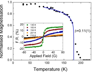
from arctan fits to hysteresis loops collected as a function of temper-ature (select loops shown in inset with half point density for clarity). Blue line shows the results of log-log fitting. . . 62 4.8 Log-log analysis of the Fe edge magnetic ordering data from a 1.1 ML
FePd trilayer film showing the influence of TC on the data linear-ity. The maximum range over which the linear trend hold occurs at 178.8 K providing a value of 0.11(1) from the gradient of the linear fit (blue line). NearTC data points for 170 and 175 K showed signif-icant deviation from the linear trend and are outside of the plotted range. . . 63
5.1 Taken from [102]. The critical dependence of ordering temperature on layer thickness in thin transition metal films. To produce a Co magnetic lattice which orders below 300 K, a film thickness of 1-2 ML must be used. . . 66 5.2 Taken from [107]. Schematic illustration of the expected magnetic
profile in an FeZr/CoZr multilayer. The grey regions represent the regions with higher ordering temperature (CoZr), embedded in a ma-terial with a lower ordering temperature (FeZr). At low temperatures (T = T1), the magnetization is expected to be constant. At elevated temperatures, a periodic magnetic profile emerges (T = T2 and T = T3). The width of the magnetization profile is denoted by W. . . 68 5.3 Taken from [107]. MOKE data showing the magnetic ordering
be-haviour of a series of FeZr/CoZr multilayers as a function of FeZr thickness. The results of further analysis are shown in the included table. An increase in the ordering temperature is observed in the thinnest sample due to the overlap of the induced moment profiles. . 69 5.4 Simultaneously fitted hard and resonant (Fe edge) x-ray reflectivity
5.5 The structural profile of a 50-2 FeZr/CoZr multilayer, produced through the fitting of Fe edge resonant reflectivity data. A corre-sponding sample schematic is included. “FeZr Oxide” is an alloy of 93% FeO and 7% ZrO. “AlZr Oxide” is an alloy of 70% Al2O3 and 30% ZrO. The di↵erences in amplitudes of the SLDs at the CoZr positions are an artifact of rebinning. . . 73 5.6 Simultaneously fitted Fe edge x-ray reflectivity data from an
FeZr/CoZr multilayer material with FeZr and CoZr thicknesses of 50 and 2 ˚A respectively. Data were collected at the temperatures indicated by Martina Ahlberg from Uppsala University. . . 74 5.7 Magnetic profiles from fitting Fe edge reflectivity data from an
FeZr/CoZr multilayer material with FeZr and CoZr thicknesses of 50 and 2 ˚A respectively. Lower panel shows 50 K data while the upper panel shows the temperature dependence of the profile shape. 75 5.8 Magnetic hysteresis loops, as a function of temperature, from a
FeZr/CoZr multilayer with FeZr and CoZr thicknesses of 50 and 1 ˚Arespectively. . . 77 5.9 The magnetic ordering behaviour of a 50-1 FeZr/CoZr multilayer
ex-tracted from fitted hysteresis loops as a function of temperature. The data show a linear decrease in remanent moment, indicated by the broken red line, before a sharp fall to zero atTC ⇡205 K. . . 78 5.10 Log-log analysis of the magnetic ordering behaviour of a 50-1
FeZr/CoZr multialyer (points). The gradient of the linear fit (line) produces an ambiguous ordering exponent of ef f = 0.15(1). . . 79
5.11 Log-log analysis of a hysteresis loop from a 50-1 FeZr/CoZr multilayer close toTC(points). The gradient of the linear fit (line) produces an ambiguous ordering exponent of = 7(1). . . 80 5.12 A hysteresis loop from a 50-1 FeZr/CoZr multilayer at 220 K,
ap-proximately 15 K above the ordering temperature of the system. . . 82 5.13 Fe edge magnetic reflectivity data (points) from a 50-1 FeZr/Zr
5.14 The resultant magnetisation profiles from Fe edge magnetic reflec-tivity data as a function of field from a 50-1 FeZr/CoZr multilayer. A small field first aligns a uniform moment with the FeZr. Further increases in field strength lead to the stabilisation and subsequent enhancement of the induced moment profile. . . 86
6.1 Taken from [119]. Ordering exponent, , versus Fe -layer thickness, dFe, in FePd trilayer samples as determined by direct fitting and by double logarithmic plotting. The dashed horizontal lines represent of the 2D XY, 3D Ising, and 3D Heisenberg models. The solid line serves as a guide to the eye. Typical uncertainties in and thickness are indicated. . . 90 6.2 Modified from [119]. Spheres of polarised Pd form around Fe
im-purities. Further addition of Fe within the same 2D plane creates a polarised region varying only in the out-of-plane direction. The approximate distribution of Fe and Pd moments integrated in the in-plane direction are indicated. . . 93 6.3 Upper panels show resonant x-ray reflectivity data, at the Pd (black)
and Fe (blue) L3 edges, from a 1.4 ML Fe -layer in Pd. Lower panels show polarised neutron reflectivity data (red) from the same sample. Data fitting performed using GenX (green) was used to extract the element specific magnetic profiles. . . 95 6.4 Upper panels show resonant x-ray reflectivity data, at the Pd (black)
and Fe (blue) L3 edges, from a 0.5 ML Fe -layer in Pd. Lower panels show polarised neutron reflectivity data (red) from the same sample. Data fitting performed using GenX (green) was used to extract the element specific magnetic profiles. . . 96 6.5 X-ray reflectivity data, at the Pd (black) and Fe (blue) L3 edges,
from 0.7 and 1.1 ML Fe -layers in Pd. Data fitting performed using
GenX(green lines) was used to extract the element specific magnetic profiles. . . 97 6.6 The scattering length density (SLD) as a function of depth showing
6.7 The e↵ect of a changing magnetic magnetic profile shape (right panel) on the Fe edge magnetic reflectivity (left panels) from a 1.1 ML Fe -layer in Pd. Fits and profiles carry corresponding colours. No significant change to the quality of fitting is observed between profile shapes; the modification of interface moments can not be proven. . . 100 6.8 The magnetic scattering length density (SLD) as a function of depth
showing the distribution of element specific magnetic moments for a varying Fe -layer thickness in a Pd/Fe/Pd trilayer at 10 K (Pd and PNR) or 30 K (Fe). . . 101 6.9 Incomplete layer coverage associated with fractional monolayers
illus-trated in the 1.4 and 0.7 ML regimes. Areas with greater and lesser concentrations of Fe have a discrepancy inTCproducing a broadening of the magnetic ordering response. . . 102 6.10 Upper panels show the structural (reflectivity) and magnetic (F.R.)
contributions to the magnetic x-ray reflectivity (points) of a 5% FePd alloy. Data were collected at 10 K at the Pd L3edge with the incident photon polarisation reversed at each point. The GenX simulation (line), and resulting magnetic scattering length density profile (lower panel), shows uniform magnetisation throughout. . . 104 6.11 Left and right panels show Pd edge hysteresis loop data (points) fitted
to pairs of arctan functions (lines) for 5% FePd alloy and 0.7 ML FePd trilayer films respectively. Temperatures are given as fractions ofTC, whereTC(Alloy) = 267.5 K andTC(Trilayer) = 117 K. . . 105 6.12 A comparison between the zero-field magnetic susceptibilities of a 5%
FePd alloy and a 0.7 ML FePd trilayer. The alloy material displays a uniform susceptibility with a sharp peak atTC(broken line) indicative of a uniform loss of the magnetic moment throughout the sample. The broad susceptibility peak displayed by the trilayer characterises a narrowing polarised region. Temperatures are given as fractions of
TC, where TC(Alloy) = 267.5 K and TC(Trilayer) = 117 K. . . 106 6.13 Left and right panels respectively show Fe and Pd edge hysteresis
6.14 The magnetic ordering behaviour of Pd moments from a 0.5 ML Fe -layer in Pd. The blue line is a linear least squares fit to the log-log data (lower panel) additionally translated onto the linear scale (upper panel) for illustrative purposes. Lower temperature data are not included in the fit as the data deviate from critical behaviour. . 108 6.15 Power-law scaling behavior of the two magnetic sub-lattices as a
func-tion of reduced temperature (left) with data o↵set for clarity. E↵ ec-tive scaling exponents as a function of Fe thickness (right). The Pd exponents (black circles) closely follow the exponents determined us-ing MOKE [119] (broken line). The Fe exponents (purple squares) could only be measured for samples with an Fe thickness 1 ML. . . 109 6.16 Normalised magnetisation of the Fe (squares) and Pd (circles)
sub-lattices for the 1.4 ML Fe sample as a function ofT /TC. The best fit to an e↵ective critical exponent is shown by solid lines with the low temperature behavior parameterised by a polynomial (broken line). Inset: Ratio of the two fitted curves shows a linear dependence with normalised temperature over the range 0.2T /TC0.8. . . 112 6.17 Fe XMCD as a function of energy in a field of 80 G. A clear magnetic
signal with the expected shape and sign reversal is observed at the L2,3edges for the 0.7 ML sample (line). No detectable magnetic signal was seen for the 0.5 ML sample (squares). Inset: Field dependence of the XRMS (points) and Langevin fit (line) from the 0.7 ML sample as a function of temperature. . . 114 6.18 Element specific magnetic ordering data (left panel), from an Fe5Pd95
alloy, show identical behaviour approachingTC with prominent field induced tails in the Fe moments above TC. Both show mean field behaviour extracted from the log-log data (lower right). Pd edge hysteresis loops (upper right) show no change in field response as the transition is approached. . . 116
7.1 AFM image of circular FePd alloy islands on a square grid. Blue arrows indicate two possible magnetic vortex arrangements. . . 122 7.2 AFM image of an array of 400 nm Pd/Fe0.6 ML/Pd circular islands
7.3 Pd edge magnetic hysteresis loops collected in the specular scattering condition (left panel) and 1 satellite peak position (right panel) from an array of 450 nm FePd alloy islands on a 500 nm square grid. Coloured dots indicate field values later used for rocking curves. . . . 128 7.4 Upper and lower panels respectively show structural and magnetic
contributions to the Pd edge rocking curves across the specular and
±1 satellite peaks, from an array of 400 nm FePd alloy islands on a 500 nm square grid, with a fixed qz of 0.0953 ˚A 1. Data were
collected at saturating fields of ± 40 mT. The specular peak shows fitted Pearson VII function (dotted line), as discussed in the text. . . 129 7.5 Upper and Lower panels respectively show the structural and
mag-netic contributions to the Pd edge rocking curves across the 1 satel-lite peak from an array of 450 nm FePd alloy islands on a 500 nm square grid. . . 130 7.6 Magnetic contributions to the Pd edge rocking curves across the 1
satellite peak from an array of 450 nm FePd alloy islands on a 500 nm square grid. Field values correspond to the coloured dots indicated in figure 7.3. . . 131 7.7 Squares and circles respectively show the inter-island ordering
tem-perature, as a fraction ofTC, from a 1.2 ML and 0.6 ML Fe -layer in Pd, as a function of inverse island diameter. Taken with permission from [135]. . . 133 7.8 Left panels show structural (upper) and magnetic (lower)
contribu-tions to a Pd edge magnetic rocking curve, from 400 nm circular Pd/Fe/Pd islands on am 800 nm square grid, displaying periodici-ties governed by the in-plane structure. Right panel shows Pd edge hysteresis loops (points), collected at the indicated positions, fitted to pairs of arctan functions (lines). The dominance of the structural component of the total scattering suppresses the observed F.R. in the specular condition. The Sum is normalised to 1 for convenience. . . 134 7.9 Upper and lower panels respectively show structural and magnetic
7.10 Comparison of loops from dots (left) and continuous film (right). Data (points) are fitted to arctan functions (lines) to enable the mag-netic ordering behaviour to be reliably extracted. Temperatures are given as a fraction ofTC, whereTC= 117 and 124 K for the patterned and continuous films respectively. . . 138 7.11 Field dependent magnetic ordering from a continuous Pd/Fe/Pd
tri-layer film, with an Fe -tri-layer thickness of 0.7 ML. The data are nor-malised to H=2 mT at 15 K. . . 140 7.12 Field dependent magnetic ordering from 400 nm circular Pd/Fe/Pd
dots on an 800 nm square grid with an Fe -layer thickness of 0.6 ML. The data are normalised to H=2.06 mT at 10 K . . . 141 7.13 Zero-field magnetic susceptibility from FePd trilayer in both 0.6 ML
Acknowledgments
I must first express my gratitude to my supervisor, Dr Thomas Hase. Not only
for providing me with the excellent opportunity to continue my studies, but for
providing me with help and support throughout the years we have worked together.
I would also like to extend this gratitude to the wider physics department at the
University of Warwick for providing a friendly and engaging work environment where
I have spent many happy years. I would like to thank the members of the materials
physics department at the University of Uppsala. In particular I would like to
thank Martina Ahlberg, Dr Unnar Arnalds, Dr Matts Bj¨orck and Prof. Bj¨orgvin
Hj¨orvarsson with whom I had the great pleasure of working closely.
This work would not have been possible without the help from the
instru-ment scientists at the various facilities visited throughout the course of my doctoral
studies. This includes, but is not limited to, Dr Laurence Bouchenoire and Dr Paul
Thompson at XMaS, Dr Daniel Haskel, Dr Yongseong Choi and Dr Jonathan Lang
at 4-ID-D, Dr Cecilia S´anchez-Hanke at X13A and Dr Christy Kinane at CRISP.
Their generosity with time, knowledge and expertise not only ensured the success
of our many experiments, but was invaluable to my overall development and
un-derstanding of the field. I would also like to gratefully acknowledge the financial
support of the EPSRC.
Finally, I would like to express my ultimate thanks to my family, and in
Declarations
This thesis is submitted to the University of Warwick in support of my application
for the degree of Doctor of Philosophy. It has been composed by myself and has not
been submitted in any previous application for any degree.
Unless otherwise stated, the responsibilities for the data presented are as
follows:
The measurements in chapter 5 were performed at the X13A beamline at
the NSLS by the author, Dr Thomas Hase and Dr Matts Bj¨orck. The temperature
dependent reflectivity data in figures 5.4 and 5.6 were collected by Martina Ahlberg
and collaborators at the University of Uppsala. All data analysis and fitting in this
chapter was performed by the author under the supervision of Dr Thomas Hase.
The measurements in chapter 6 were performed at the 4-ID-D beamline at the APS
by the author, Dr Thomas Hase, Dr Laurence Bouchenoire and Dr Paul Thompson,
and using the CRISP instrument at the ISIS facility by the author and Dr Thomas
Hase. The Fe edge data in figure 6.18 were collected at U4B at the NSLS by Dr
Thomas Hase. All data analysis and fitting in this chapter was performed by the
author under the supervision of Dr Thomas Hase. The measurements in chapter 7
were conducted at the XMaS beamline at the ESRF and at the 4-ID-D beamline at
the APS by the author, Dr Thomas Hase, Dr Laurence Bouchenoire and Dr Paul
Thompson. The SEM images in figure 7.1 and 7.2 were provided by Dr Unnar
Arnalds at the University of Uppsala. All data analysis and fitting in this chapter
was performed by the author under the supervision of Dr Thomas Hase.
All samples used in this thesis were prepared by Martina Ahlberg, Dr Unnar
Publications
Publications based on work presented in this thesis:
The e↵ect of proximity on the magnetic ordering in itinerant Pd/Fe/Pd
heterostructures
Thomas P. A. Hase, Matthew S. Brewer, Unnar B. Arnalds, Martina Ahlberg,
Vassil-ios Kapaklis, Matts Bj¨orck, Laurence Bouchenoire, Paul Thompson, Daniel Haskel,
Yongseong Choi, Jonathan Lang, Cecilia S´anchez-Hanke, and Bj¨orgvin Hj¨orvarsson
Submitted to: Physical Review X
Element resolved magnetization profiles in Pd/Fe/Pd trilayer
M.S. Brewer, U.B. Arnalds, E. Holmstr¨om, M. Bj¨orck, G. Andersson, M. Ahlberg,
V. Kapaklis, L. Bouchenoire, P.B.J. Thompson, D. Haskel, J. Lang, C. S´
anchez-Hanke, C.J. Kinane, B. Hj¨orvarsson and T. P. A. Hase
In Prep for: Journal of Physics: Condensed Matter (Letters)
Reflectivity Studies of Magnetic Heterostructures
Matts Bj¨orck, Matthew S. Brewer, Unnar B. Arnalds, Erik ¨Ostman, Martina Ahlberg,
Vassilios Kapaklis, Evangelos Th. Papaioannou, Gabriella Andersson, Bj¨orgvin
Hj¨orvarsson and Thomas P.A. Hase
Thermal transitions in nano-patterned XY-magnets
Unnar B. Arnalds, Martina Ahlberg, Matthew S. Brewer, Vassilios Kapaklis,
Evan-gelos Th. Papaioannou, Masoud Karimipour, Panagiotis Korelis, Aaron Stein,
Sveinn ´Olafsson, Thomas P. A. Hase and Bj¨orgvin Hj¨orvarsson
Submitted to: Applied Physics Letters
Other Publications:
Growth and characterisation of NiSb(0001)/GaAs(111)B epitaxial films
James D. Aldous, Christopher W. Burrows, Ian Maskery, Matthew Brewer, David
Pickup, Marc Walker, James Mudd, Thomas P. A. Hase, Jon A. Du↵y, Stuart
Wilkins, Cecilia S´anchez-Hanke and Gavin R. Bell
Journal of Crystal Growth,3571-8 (2012)
DOI: 10.1016/j.jcrysgro.2012.07.010
Depth-dependent magnetism in epitaxial MnSb thin films: e↵ects of
sur-face passivation and cleaning
J.D. Aldous, C.W. Burrows, I. Maskery, M.S. Brewer, T.P.A. Hase, J.A. Du↵y, M.R.
Lees, C. S´anchez-Hanke, T. Decoster, W. Theis, A. Quesada, A.K. Schmid and G.
R. Bell
Journal of Physics - Condensed Matter, 2414 146002 (2012)
Abstract
Detailed knowledge of the interaction of magnetic moments is key to develop-ing the next generation of magnetic devices. Systems with induced moments provide an ideal regime in which to study this fundamental behaviour. Resonant x-ray scat-tering and polarised neutron reflectivity are complementarily used to map induced moment profiles in continuous FeZr/CoZr multilayer films and both continuous and patterned Pd/Fe/Pd trilayer films. Resonant scattering is additionally employed to measure the dimensionality of the magnetic lattice through observations of the magnetic ordering behaviour.
The shape and extent of the induced profiles was resolved with unprecedented accuracy, and was found to conform to the theoretical expectation: all profiles de-cayed exponentially from the inducing material, with an extent in the nm regime. Adjacent magnetic lattices were found to interact only through the magnitude of their moments, acting through the magnetic susceptibility of the induced material. The dimensionality of adjacent magnetic lattices were therefore found to be inde-pendent. Additionally, a significant, and unexpected, observation was made of the thinnest Fe layers studied: the Fe moment was seen to vanish though a pronounced induced moment remained in the neighbouring Pd. The definitive cause of this un-usual behaviour has yet to be discovered. In the patterned materials, the interaction between adjacent islands was found to contribute minimally to the overall behaviour in the geometry studied. The energy cost of rotating the moments within an indi-vidual island was the dominating contribution to the magnetic ordering behavior.
Chapter 1
Motivation
Technological advancements have historically often been linked with a novel ex-ploitation of artificially created materials, or the modification of material properties to meet the requirements of a novel application. In its simplest and earliest form this might involve increasing the strength and durability of a material, for example adding carbon to iron to produce steel. Centuries later, the same process can now be seen in modern transistors where silicon is doped with, for example, phosphorous or boron to produce the requisite semiconducting properties.
For these advancements, both the understanding of material properties and manufacturing processes must be sufficiently developed. Manufacturing methods have, however, developed to the point of atomic scale precision [1]. The only real barriers remaining are the time and cost of production, and sufficient understanding of fundamental material properties. The latter drives a wealth of diverse research projects at institutions around the world [2–7]. This project concentrates on the magnetic properties of layered materials and the atomic scale magnetic interactions at the interfaces therein. Magnetism is a property which is commonly exploited in computing, most notably in magnetic hard disk drives [8].
loss of data [10, 11]. The continuous magnetic film is patterned into islands, each representing an individual data bit, which are physically separated to prevent amal-gamation. The interplay between adjacent magnetic islands is, however, governed by a wealth of competing interaction processes which need to be fully understood before such a device can be successfully realised and its limitations quantified.
Another emerging field reliant upon magnetic processes is that of ”spin-tronics” [12]. Spintronic logic devices are a proposed successor to the electronic transistor; a device already reduced in size to a point which approaches the limit of what is practically achievable [13].
The now famous Moore’s Law [14], describing the exponential increase in transistor density over time, cannot continue indefinitely using traditional silicon semiconductor devices. Though the hard limit on transistor size may be the atomic scale [15], the practical limit is dictated by power, i.e. the amount of energy required per unit time for the transistor to operate, as electronic devices rely on manipulating packets of charge to perform computational tasks. As the devices reduce in size, the power density increases to unmanageable levels. A new branch of devices, known as “spintronic” devices, are being developed with the aim of overcoming this limitation [12]. Spintronic devices manipulate the electron spin, rather than the traditional method of exploiting the charge, to transmit information. The electron has two convenient spin states (up and down) in which it can exist, which can represent 1 and 0. In theory then, a single electron could carry a individual bit of information throughout a logic process. Creating and controlling a spin-polarised current can only be achieved using magnetic materials [16]. Fundamental magnetism research in this area must pay particular attention to the magnetic properties at material interfaces, as it is the control of the electron spin across such interfaces that is critical to the realisation of a device of this type [12, 17].
scale interactions can be investigated [18–20]. Reduced dimensionality systems, i.e. ultrathin systems which can be considered two dimensional, represent an ideal example for study, as by their nature they have properties di↵erent to that of their bulk, three dimensional counterparts [21, 22].
To study magnetic interactions within such systems, it is necessary to in-clude interfaces between di↵erent regions displaying di↵erent magnetic behaviour. A convenient method to enable this is to study polarisable materials. These do not display a natural spontaneous moment, but gain an induced moment when in prox-imity with a magnetic material [23]. This provides not only an interface across which the magnetic moments are fundamentally coupled, but removes the added influence of a second magnetic layer with potentially independent magnetic bulk properties. The interface between a ferromagnetic and polarisable material then represents the desired interface between regions displaying non-bulk properties, providing an av-enue for studying the fundamental, atomic scale, magnetic interactions in a coupled magnetic system.
Chapter 2
Introduction
2.1
Magnetism
Magnetism has a quantum mechanical origin due to the intrinsic angular momentum of electrons, which is referred to as theirspin. The spin moment of each electron is dictated by its spin quantum number, which can only take one of two values±1/2, which produces angular momenta of S~ =±¯h/2 [23]. These are commonly referred to as spin-up and spin-down. The measurable spin moment, along an applied field direction, produced by the angular momentum of a single electron can be calculated using [24]:
µS=g
e
2me
~
S, (2.1)
whereeis the charge carried by an electron,meis the rest mass of an electron, and
g ⇡ 2. This produces spin-moments of ±µB. However, an electron bound to an atom has an additional moment due to its orbit around the nucleus, analogous to the path of an electric current within a solenoid. These spin and orbital moments are electromagnetically coupled through the spin-orbit interaction [23]. This leads to a subtle energy shift between electrons of opposing spin states within the same electron orbital. In the simplest model, these electron orbitals fill in accordance with Hund’s rules [23]. For an isolated atom, these rules are followed to ensure the lowest possible energy state is realised, i.e the orbital half fills with electrons which are in an identical spin state, filling all available spaces for this spin state before the opposite spin state is allowed.
moment. In materials with highly localised outer shells, such as the f-shell, the sharing of electrons with neighbouring atoms is not energetically favourable, leading to a retention of a strong orbital moment. Materials in which this occurs are the “Rare Earths” such as Gd and Ho [25].
There is another class of materials within the periodic table which can show spontaneous magnetic order. These are the transition metals Fe, Co and Ni. Rather than being highly localised, the outer d-bands of these metals overlap [26], allowing them to share electrons in anitinerant electron band. To understand the origin of a spontaneous moment in an itinerant system, the energy of electrons within this conduction band must be considered.
2.1.1 Itinerant Magnetism
In an itinerant, delocalised electron band, the orbital moment is minimised as the electrons no longer follow well defined orbital paths. The electrons can be considered
orbitally quenched [27]. The spin-orbit interaction is subsequently minimised and
all electrons can be assumed to have the same energy. The lowest energy state is therefore realised through a population with equal numbers of spin-up and spin-down electrons, as the nett moment is minimised. These populations can be considered as two equally populated electron sub-bands. However, in order for a material to be magnetic, there must be a population di↵erence between these two sub-bands (creating a nett spin moment), which increases the kinetic energy of the electron system making it energetically unfavourable.
One way in which a population imbalance can be stimulated is through the application of an external magnetic field [28]. If a field is applied, a shift in the energy levels of the two spin states at the Fermi energy occurs [23]. This lifts electrons in one band above the Fermi energy while lowering the energy in the other sub-band. This arrangement is energetically unfavourable, and so those electrons above the Fermi energy reverse their spin and swap sub-bands. This creates the desired population imbalance between the number of electrons with each spin, and so a magnetic moment is formed. This e↵ect is Pauli paramagnetism [29]. The magnetic moment, M, induced by applied field, H, in a Pauli paramagnet then follows the relation
M = P·H, (2.2)
temperatures. Above the magnetic ordering temperature (discussed in section 2.1.2), thermal excitations cause the spontaneous moments carried by the atoms within the lattice to lose alignment with their neighbours resulting in zero nett moment [30]. An applied field exerts a torque on each moment which seeks to align them with the applied field direction and generate a nett moment once more. Paramagnetic systems revert back to the equilibrium state, and lose their gained nett magnetic moment, if the applied field is removed.
The second process which can result in a population imbalance between the two spin-states arises due to a significant, additional contribution to the total en-ergy from the exchange interaction between electrons; the result of the overlap of the electron wavefunctions [31]. In order to obey exchange symmetry, the total wave-function, comprised of spin and spatial contributions, of two interacting electrons must be antisymmetric [23]. If the spin-states are symmetric (i.e. the spins align) then the spatial state must be antisymmetric which, due to the exchange interac-tion, allows the electrons to be further apart in real space, reducing the electrostatic potential [31]. This means that if the electron density of states is sufficiently high, the spins will begin to align spontaneously. In order that each band is filled exactly to the Fermi energy, the more populated band shifts to a lower energy while the less populated band shifts to a higher energy. The nett result is the same as that of the Pauli paramagnetic response outlined above. The exchange interaction thus leads to an additional contribution to the magnetic susceptibility, known as the Stoner factor [32]. The total susceptibility becomes [23]
meas= P
1 U ·D(EF)
= PS, (2.3)
where U is the coulomb energy due to the exchange interaction, D(EF) is the electron density of states at the Fermi energy, andSis the Stoner enhancement factor [32], a temperature dependent material property [29]. The onset of ferromagnetic order is then defined as the point at which an infinite susceptibility can first exist [30], and so materials are ferromagnetic if they satisfy the relation:
U·D(EF) 1. (2.4)
This non-zero coercivity causes a magnetic hysteresis e↵ect meaning the magnetic moment is not only dependent on the applied field strength, but the history of the applied field [24]. This will be discussed in more detail in section 2.3.2.
When considering a magnetic material above the atomic scale, it is conve-nient to ignore the behaviour of individual itinerant electrons in the Stoner Model, and instead consider each atom as an independent magnetic particle coupled to those around it. This forms the basis of the Curie-Weiss Model [24]. In this Model, the magnetisation within a solid permeates the system as a lattice of coupled moments centred at the atomic positions. Each moment is coupled to each neighbouring moment with a strength defined by the moments and the coupling constant, J. Immediately, this simplification ignores long-range interactions. A further simpli-fication can be made by ignoring local variations in J and instead assuming that each neighbouring pair of moments is coupled by the average value of J through-out the lattice. This is the basis of mean-field theory [24], which is sufficient for a basic description of the lattice behaviour. By summing over all interactions, the Hamiltonian for such a system can then be described as
H= 1 2
X
i6=j
Jmi·mj, (2.5)
whereiandjare the atomic indices andmi/j are the atomic moments. IfJ >0, the magnetic potential described by the Hamiltonian is clearly maximised for collinear moments and thus ferromagnetic alignment represents the energetic ground state. Conversely, ifJ <0, antiferromagnetic alignment is energetically favourable. Ther-mal energy within the system seeks to misorientate the aligned moments. The energy required to overcome the magnetic potential leads directly to an approxima-tion of the temperature above which spontaneous magnetisaapproxima-tion is lost; the Curie Temperature, TC. Investigating the manner in which these magnetic bonds break, through the application of heat, can elucidate the true nature of the coupling be-tween adjacent moments. Thus, measurements of the global magnetic response can indirectly probe the magnetic behaviour on a fundamental scale. This is the basis of magnetic ordering studies.
2.1.2 Magnetic Ordering
[33] shows the order disorder transition is governed by a simple power law:
M /(TC T)1/2. (2.6)
This simple model, however, breaks asTCis approached as it assumes that all regions of the sample remain the same. This is clearly unphysical as certain moments begin to reverse. It also ignored the magnetic correlations associated with long-range order which become critical as TC is approached [34]. To more accurately describe the ordering behaviour, a less simplistic approach is required.
To determine the nature of the coupling within the lattice, the first indicator is the ordering temperature: a higherTC means stronger coupling. However,TC is strongly influenced by, for example, the finite volume of the sample [35, 36]. A more illustrative measure can therefore be how rapidly the magnetisation is lost asTC is approached. In the Landau model, the exponent of 0.5 crudely predicts that all lattices will approachTC similarly. However, the actual behaviour is dictated by the allowed orientations of the moments within the lattice, because a magnetic lattice of coupled moments, with a magnetic potential described by equation 2.5, has an energy cost for reorientating an individual moment.
The impact of this energy cost can be determined by considering the Helmholtz free energy, which for a ferromagnetic system can be described as:
E =U T S, (2.7)
If an additional spacial dimensionality is included, creating the 2D Ising system, a magnetic defect can extend over both dimensions. The energy cost of creating a defect scales with the defect size. However, the entropy gain can also be shown to scale with the defect size [38]. This creates a regime in which magnetic order can exist, even for an infinite system. In any magnetically ordered lattice, there will be a finite temperature above which T S exceeds U and the magnetic order is lost. This is an alternative description of the Curie Temperature, TC. As a 2D Ising system approaches TC, the high energy cost of reversing an individual moment leads to the preservation of the total magnetic moment until T is very close toTC. At this point, the thermal excitations are sufficient to reverse a significant proportion of individual moments and the magnetisation very rapidly diminishes to zero [30].
The magnetic moments within the lattice can also be allowed additional de-grees of freedom. If one additional degree of freedom is introduced, so that moments are constrained to point in any direction within a 2D plane, the XY (d = 2) spin system is formed. The final, third degree of freedom allows the moment to point in any direction, forming the Heisenberg,d= 3, system.
In both of these cases, the energy required to reorient a moment becomes a function of the degree of reorientation, with the minimum energy tending to zero. This produces regimes in which magnon modes can exist. These are the magnetic equivalent of phonon modes and are magnetic excitations mediated through the magnetic lattice. The number of magnon modes which are excited then dictates the degree of magnetisation which is lost from full alignment. This can be achieved by integrating the magnon density of states and, for a 3D Heisenberg system, results in Bloch’s law [39] which states that, in the low temperature region,
M =MT=0 aT3/2, (2.8)
long-ranged, and are thus suppressed allowing ferromagnetic order to be preserved. A 3D Heisenberg system, can dissipate thermal energy with much greater efficiency than an Ising system generally leading to a significant increase inTCand resulting in a much more gradual decline in the nett moment of the lattice asTC is approached [30].
In the 2D XY system, the addition of anisotropy is not sufficient to pro-duce a globally ordered phase at any finite temperature. Instead, the moments form into a pseudo-ordered vortex state, where the moments form into concentric rings. The energetic ground-state of such a vortex system produces equal numbers of clockwise and anti-clockwise vortices (vortices and anti-vortices) which form into pairs in order to minimise the free energy. These vortex anti-vortex pairs have a small nett moment. However, these pairs also have a lower entropy than unpaired vortices. As the temperature increases, the entropy term of the free energy begins to dominate and it becomes energetically beneficial for the pairs to separate. Un-paired vortices carry no nett moment. This is a topological phase transition called the Kosterlitz-Thouless-Berezinskii transition [41] which allows the ordering of the otherwise disordered 2D XY phase.
As these di↵erent states have di↵erent expected behaviours as they approach
TC, their combination of spin and spacial dimensionalities can be investigated by observing the magnetisation as a function of temperature. The Landau model (equa-tion 2.6) can then be expanded upon by allowing the exponent to di↵er for di↵erent ordering models. The magnitude of the total moment (i.e. the moment summed over the whole lattice) is then described by a power law where the magnetisation,
M, as a function of temperature, T, is of the form
M = (TC T) , (2.9)
Spin(d) Spatial(D)
0.125 1 2
0.23 2 2
0.31 1 3
0.33 2 3
[image:33.595.248.394.111.213.2]0.35 3 3
Table 2.1: Critical ordering exponents, from [30].
These exponents are the result of experimental determination with the ex-ception of the 2D Ising case for which this exact solution can be derived. Due to the similarity in exponents, the di↵erence between the magnetic responses for these di↵erent dimensionalities is quite subtle. Idealised plots of the normalised magnetic ordering behaviour for 2D Ising, 2D XY and 3D Heisenberg classes are illustrated in figure 2.1. As M(T = 0) and TC are material dependent quantities, both are normalised to 1 to aid visual comparison.
Ideal critical ordering behaviour is difficult to achieve experimentally; any sample or field inhomogeneity will cause small variations in local magnetic be-haviour. In the simplest case, this will lead to a distribution of ordering tem-peratures within the material. A Gaussian distribution of ordering temtem-peratures causes a Gaussian convolution to be applied to the ordering data. The most pro-nounced e↵ect of this convolution is a residual moment above TC manifested as an extended tail in the ordering data. However, the data will be subtly altered at all temperatures, with the critical ordering exponent, , also subtly altered.
Figure 2.1: The expected temperature dependent magnetisation curves for univer-sality classes with ideal critical exponents (solid lines). Dashed line shows a Gaussian convolution to the 2D Ising case to show the influence of field or sample inhomo-geneity on the magnetic ordering. TC and M(T = 0) are arbitrarily normalised to 1 to aid visual comparison.
= 1
(T c T) , (2.10)
where is a critical exponent. This technique is employed to analyse data above
TC making it a useful, complementary technique to analysis ofM(T) through . A final critical exponent can be extracted from the magnetic response to the applied field atTC, which follows the relation [24]
M =H1/ , (2.11)
governed by a third critical exponent, . These three ordering exponents are clearly highly correlated, and in fact it can be shown that the three are related through the Widom equality [42]:
Spin(d) Spatial(D)
7/4 15 1 2
- 15 2 2
[image:35.595.222.420.111.212.2]1.2373(2) 4.78 1 3 1.3177(5) 4.81 2 3 1.388 4.78 3 3
Table 2.2: Critical exponents compiled from [30] and [24].
More practically, both and have theoretically or experimentally determined values for each universality class, shown in table 2.2. is omitted for the 2D-XY case as it is not defined, due to the evolution of magnetic correlation lengths within the array. As discussed, is dictated by the susceptibility of the system just above the ordering temperature. Above the ordering temperature, the moments are globally disordered, but some localised order may remain. The magnetic correlation length, which will be discussed in more detail in chapter 7, is a measure of the size of these locally ordered regions. Kosterlitz [41] showed that the correlation length,
⇠, in the 2D-XY regime varies as
⇠⇡exp⇣b(TC T)1/2
⌘
, (2.13)
where b = 1.5. Similarly, the susceptibility, rather than being governed by the Curie-Weiss law, follows the relation
⇡exp (b(TC T)(2 ⌘)), (2.14) where⌘is the critical exponent of the correlation function, and in this case is equal to 1/4. In this thesis, phase transitions with various dimensionalities will be studied. In order to consistently perform this analysis, the magnetisation as a function of temperature will predominately be investigated, and so is the experimental value of interest.
be termede↵ective exponents denoted, for example, ef f, to distinguish them from
determinations of bulk behaviour. These e↵ective exponents are still meaningful, and may still fall into one of the described universality classes. However, the e↵ect of interfaces on the magnetic lattice can not be ignored.
2.2
The Magnetic Interface
As metallic heterostructures reduce in size, the magnetic behaviour will begin to deviate from that of the bulk because of the added influence of the material interfaces [43–45]. This has two contributing factors: the termination of the magnetic lattice, and shape anisotropy.
The termination of the magnetic lattice necessarily results from the termina-tion of the crystal lattice at a material surface. Within the Curie-Weiss descriptermina-tion, this termination leads to a modification of the magnetic behaviour of those moments closest to the interface due to a reduction in coupled nearest neighbours. The range of interactions is not, however, limited to nearest neighbour interactions in real sys-tems; the greater the range of magnetic interactions, the further from the interface deviation from bulk magnetic properties will be observed.
This phenomenon was explored by Taroni and Hj¨orvarsson [46] who per-formed simulations on freestanding magnetic lattices of Ising spins. For a 10 mono-layer (ML) film, assuming only nearest neighbour interactions, TC was seen to de-crease to 0.96 of that of an otherwise identical 40 ML film. The ordering behaviour was found to di↵er as a function of depth, as shown in the upper panel of figure 2.2 with an overall ef f of 0.23. The simulation was repeated assuming the range of
interactions was five interatomic distances (lower panel figure 2.2). Clearly the e↵ect of the interface permeates further into lattice. This e↵ect lead to a greater relative reduction in TC to 0.92 of that of an otherwise identical 40 ML film. With this greater interaction range, ef f was 0.40. This pronounced change in the e↵ective
exponent, induced by changing only the range of interactions, is greater than the di↵erence expected of a dimensionality change (see table 2.1). This highlights the critical importance of interfaces in systems with reduced size, and also the difficulty in robustly determining the dimensionality of a terminated lattice.
Figure 2.2: Taken from [46]. The simulated magnetic ordering behaviour of a free-standing, cubic lattice of Ising spins with a thickness of 10 ML. Upper and lower panels show the influence of the interfaces when considering the range of interactions to be 1 and 5 interatomic distances respectively.
support magnetic excitations in a direction forbidden in another. If a 2D lattice is magnetically adjacent to a 3D lattice, will the interaction between 2D and 3D mo-ments stimulate magnetic excitations in the forbidden direction of the 2D lattice? The nature of the interactions at such an interface is poorly understood.
The second significant contribution is due to magnetic anisotropy, i.e. the preferential alignment of the magnetic moments along particular directions. A bulk, amorphous material, can be considered isotropic. A crystalline material is subject to magnetocrystalline anisotropy, where the crystal structure dictates preferential directions for magnetic alignment. In the simplest case, an infinite 2D rectangu-lar lattice of moments will have a magnetic easy axis along the minor axis of the rectangle and a hard axis along the major axis. The easy axis represent the en-ergetic minimum for the moment orientation, and the hard axis represents a local maximum. An applied field can align the moments to another direction if the field strength is sufficient to overcome the energy barrier. If the lattice is truncated those moments at the periphery will have an additional energy cost if they are aligned perpendicular to the interface. There then exists a competition between the latter
shape anisotropy and the former magnetocrystalline anisotropy.
It is clear then that the e↵ect of magnetic interfaces and truncated systems can have a significant e↵ect on a wealth of magnetic properties including the mag-netic ordering behaviour, the ordering temperature and the moment orientation. In this work, systems with reduced dimensionality will be investigated. In partic-ular, the e↵ect of a reduction in spacial extent of a film on the magnetic ordering dimensionality will be investigated.
2.2.1 Magnetic Proximity E↵ect
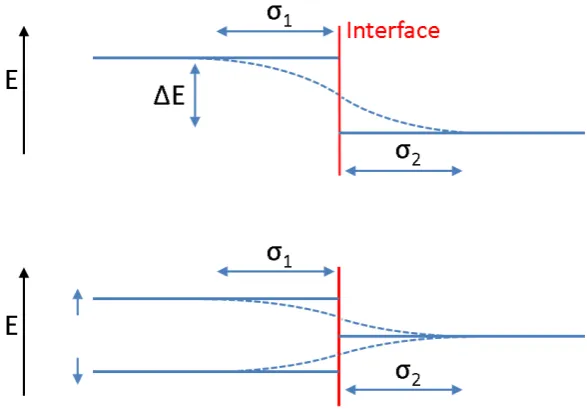
When considering the magnetic interface, it is prudent to consider the chemical po-tential between atomically adjacent materials, i.e. the interaction of electrons across the interface. In a metallic heterostructure, materials on both sides of an interface will have conduction electrons. These itinerant electron bands will hybridise and influence each other [47]. This can give rise to an observable e↵ect whereby mag-netisation is stimulated in some materials when adjacent to FM materials. This is known as the magnetic proximity e↵ect. This results in the stimulation of ferro-magnetic order in a paraferro-magnetic material through direct contact with an inducing ferromagnet [48].
individ-Figure 2.3: Electron di↵usion produces a gradual and continuous transition in the electron energy across a material interface (upper panel). If one of these materials has a spin-split band, this splitting permeates into the neighbouring material (lower panel).
ual electrons not bound to particular atoms [47]. At an interface between two such materials, the electron clouds from the adjacent materials overlap and become hy-bridised. The electrons are then free to move between the two electron clouds, across the interface, as long as the nett electron flow remains zero. The potential is then blurred across the material interface as shown in the upper diagram in figure 2.3. If one of the materials at the interface is magnetic, the population imbalance between the two electron sub-bands leads to an energy di↵erence between the two. Each sub-band then has it own chemical potential at the interface to the neighbouring material, as shown in the lower diagram of figure 2.3. The electron di↵usion length within each material, , dictates the shape of this potential and is governed by the localisation of electrons within the material: localised electrons produce a narrow potential, itinerant electrons produce a broad, hybridised profile.
[image:39.595.172.466.129.337.2]induce FM order in a traditionally non-magnetic material. In practice, the material in which magnetic order can be stimulated must already be close to meeting the Stoner Criterion e.g. Pd and Pt [49]. The range of the induced magnetic moment is limited by the spin di↵usion length, i.e. the finite penetration depth over which the polarisation of the di↵using electrons is maintained. Beyond this distance, scatter-ing processes lead to the equilibrium spin state of the material bescatter-ing met, and any modification to the electron population being lost.
In the case of the itinerant paramagnet Pd, a material which is very close to fitting the criteria for spontaneous ferromagnetic order, atomic contact with a ferromagnetic material such as Fe, leads to a hybridisation of the Fe 3d and Pd 4d electron bands. This increases the electron DOS sufficiently in the 4d electron band causing the band to become exchange split, and thus the Pd to become indepen-dently, spontaneously ferromagnetic [50]. The inverse process, unpolarised electrons di↵using from the PM into the FM, can lead to the suppression of FM order in typically FM materials [51].
Due to the finite probability of the di↵using electron undergoing a spin-flipping scattering event per unit distance, the nett polarisation of the di↵using electrons exponentially tends towards that of the conducting material with increas-ing distance from the interface. A semi-quantitative description of the polarisation, is given by [52]:
S(r)⇠ P 3k2
F
⇡r exp (
2kFr
p
S/3) (2.15)
wherer is the distance from the polarising atom, P is the Pauli susceptibility, kF
is the wave vector at the Fermi surface, andSis the Stoner enhancement factor. As the magnetisation is likely to scale with the degree of polarisation of the di↵using current, this description can be applied to the magnitude of the induced magnetic moment. The range of the induced moment is therefore dependent only upon ma-terial constants and the temperature dependent Stoner factor,S. A modification to this polarisation description arises due to long-ranged RKKY interactions [53–55]. The influence of these interactions is oscillatory as a function of distance from the material interface, successively enhancing and suppressing the polarisation. As the e↵ect is small relative to the contribution described by equation 2.15, it only pro-vides a noticeable contribution in the outermost polarised regions. For simplicity, it will be ignored.
at an interface can be studied. The magnetic behaviour at interfaces is a crucial area of study for the realisation of spintronic devices which rely on the manipulation of spin polarised currents across material interfaces. Conducting a spin polarised current can only be achieved using magnetic materials. Due to the hybridisation of the electron bands at such an interface, the magnetisation at the interfaces are intrinsically coupled. The nature of this coupling is, however, poorly understood. In patterned materials, desirable for magnetic data storage devices, additional inter-actions between the islands are introduced, adding a further layer of complexity to the magnetic coupling present in the system. To study these types of interactions, methods for probing the behaviour of the magnetic lattice are therefore required.
2.3
Studying Magnetism
Studies of the magnetic ordering behaviour, which are necessary to probe the cou-pling within the magnetic lattice, are commonly conducted using Superconducting Quantum Interference Device (SQUID) magnetometry. These measurements are highly sensitive to the total moment of a sample and as such, are of particular use when studying freestanding crystals or encapsulated powders. A layered metallic sample, such as those of particular interest to this work, must be grown on a sub-strate material and may have only a small volume of the sample which is magnetic. The high sensitivity of the SQUID technique then makes any small diamagnetic or paramagnetic response from areas within the sample which are not of particular interest, difficult to remove. As the sample orientation can also not be accurately controlled, directional studies are difficult. As such, in this thesis, scattering tech-niques will be employed throughout. These involve scattering a particle (either a photon or a neutron) from the sample, and measuring the response. The details of these studies, and their sensitivity to the magnetisation within the sample will be discussed below and in the following two chapters.
Initial categorisation of samples as well as previous work was performed using the magneto-optic Kerr e↵ect (MOKE). These previous studies were performed by collaborators at the University of Uppsala and form the foundation of the studies presented in this thesis.
2.3.1 MOKE
photon polarisation with respect to the incident polarisation [56]. The electric field of an incident photon exerts a force on the photons within the target material in accordance withF =qE. The oscillatory motion of the electrons interacts with the magnetic field within the material (due to the Lorentz force law: F = q(V ⇥B), creating an additional component of the electric field vector in a direction perpen-dicular to both the magnetic field and polarisation directions, and with a magnitude proportional to the sample magnetisation. This additional component induces an ellipticity in the polarisation of the reflected photons, with a major axis rotated from the incident polarisation direction. Quantification of this Kerr rotation, typically achieved by separating the additional component from the reflected beam with a second polariser, then directly yields a value proportional to the sample magnetisa-tion.
This magnetic sensitivity can be exploited in a number of geometries in order to probe sample magnetisation in di↵erent directions. Sensitivity to the in-plane magnetisation desired in this work is possible in the “Longitudinal Geometry” shown in figure 2.4. An external field is applied in the in-plane direction using a Helmholtz coil. The angle of incidence, and thus of reflection, is fixed to be approximately 60 . This is due to the trigonometric dependence of the degree of rotation arising from the Lorentz force vector cross product. At 90 , used in the polar MOKE geometry, the additional component acts along the beam direction, producing no measurable rotation. 60 maximises the rotation, increasing signal to noise.
The high flux of modern lasers allows high count rates, and fast data col-lection. As there is little absorption of optical photons in air, experiments do not need to be conducted in vacuum allowing greater flexibility and interchangeability of sample environments. Cryogenically cooled sample environments, with optically transparent windows, incorporating electromagnetic coils allow routine access to a wide range of temperatures and fields. Optical photons, however, only have a rel-atively short penetration depth into metallic materials (typically around 20 nm) [57], potentially causing difficulties as sample thicknesses increase. MOKE is only sensitive to the volume integrated magnetisation within the penetration depth of the beam. MOKE does not provide depth resolution nor element specificity.
Figure 2.4: Longitudinal MOKE employs linearly polarised optical photons reflected o↵ a magnetic sample surface. The Kerr rotation of the major axis of the ellipti-cally polarised reflected photons, with respect to the incident polarisation, is then proportional to the in-plane sample magnetisation.
2.3.2 Magnetic Hysteresis
Magnetic hysteresis is the inability of a system with spontaneous magnetic order to reachM = 0, H= 0 through the application of an applied magnetic field. Instead, the magnetisation will trace a path around a loop centred on M = 0, H = 0 as shown in figure 2.5. The shape of the loop contains important information about the behaviour of the system.
A ferromagnetic material, when cooled from above its ordering temperature, can exhibit zero nett moment due to the formation of magnetic domains the re-orientation of which is energetically challenging [24]. With the application of an external field, the domains can be aligned. Once all the moments are aligned with the field, further increase of the applied field strength yields no further increase in sample magnetisation, and the material is said to have reached its saturation mag-netisation, MSat. The minimum field required to fully align the moments is then
HSat. An increase in temperature within a magnetic system will reduce the
Figure 2.5: Example hysteresis loop data from a system in a ferromagnetic phase (left) and paramagnetic phase (right) with key parameters indicated.
If the field is reduced from saturation, the system does not have enough en-ergy to revert back to its starting position at H = 0, M = 0 and so maintains a remanent moment, MRem. MRem, after the application of a saturating field, is an
unbiased measure of the samples temperature dependent, spontaneous magnetisa-tion since it removes the influence of the domain structures. In order to remove the sample magnetisation in a system with non-zero remanence, an externally ap-plied reversing field is required. The minimum field strength required to remove this magnetisation is the coercive field, Hc, which is a measure of the energy required
to reorientate the magnetic structures within the sample. In larger structures, the increase in sample volume makes magnetic reorientation more difficult, increasing
Hc. Conversely, thermal energy within the system makes it easier to overcome the
magnetic alignment, and thus lowersHc. The collapse of the coercive field to zero
is an accurate measure of the thermally driven loss of ferromagnetic order atTC as it necessarily coincides with the loss of the remanent moment and thus the onset of the paramagnetic phase [30].
![Table 2.1: Critical ordering exponents, from [30].](https://thumb-us.123doks.com/thumbv2/123dok_us/9557415.460415/33.595.248.394.111.213/table-critical-ordering-exponents-from.webp)

![Table 2.2: Critical exponents compiled from [30] and [24].](https://thumb-us.123doks.com/thumbv2/123dok_us/9557415.460415/35.595.222.420.111.212/table-critical-exponents-compiled.webp)
![Figure 2.2: Taken from [46]. The simulated magnetic ordering behaviour of a free-standing, cubic lattice of Ising spins with a thickness of 10 ML](https://thumb-us.123doks.com/thumbv2/123dok_us/9557415.460415/37.595.185.447.116.562/figure-simulated-magnetic-ordering-behaviour-standing-lattice-thickness.webp)

![Figure 3.6: Simulations of an [Fe50 ˚ACo5 ˚A]⇥10 multilayer on a Si substrate at both10 keV and 708 eV](https://thumb-us.123doks.com/thumbv2/123dok_us/9557415.460415/59.595.132.487.109.504/figure-simulations-fe-aco-multilayer-si-substrate-both.webp)
![Figure 4.6: The magnetic scattering length density (MSLD) can be tailored at aninterface when fitting reflectivity data using GenX [94]](https://thumb-us.123doks.com/thumbv2/123dok_us/9557415.460415/79.595.146.469.132.380/figure-magnetic-scattering-density-tailored-aninterface-tting-reectivity.webp)