University of Warwick institutional repository: http://go.warwick.ac.uk/wrap
A Thesis Submitted for the Degree of PhD at the University of Warwick
http://go.warwick.ac.uk/wrap/66903
This thesis is made available online and is protected by original copyright. Please scroll down to view the document itself.
Cyclic behaviour of external diaphragm
joint between steel I-section beam and
circular hollow section column
by
Majd Khador
A thesis submitted in fulfilment of the requirements for the
degree of
Doctor of Philosophy in Engineering
University of Warwick, School of Engineering
This Thesis is dedicated to my home country Syria
My ultimate pride and pain
3
Contents
Dedication ... 2
Contents ... 3
List of figures ... 8
List of tables ... 13
Acknowledgments ... 15
Declaration ... 17
Summary ... 18
Symbols ... 19
Abbreviations ... 29
Chapter 1
–Introduction
1.1. Advantages of hollow sections ... 321.2. Aims and objectives of this project... 35
1.3. Outline of thesis ... 36
Chapter 2
–Literature Review
2.1. Introduction ... 382.2. Moment joints to tubular columns... 39
2.3. Externally stiffened joints to tubular columns ... 44
2.3.1. T-stiffeners ... 44
4
2.3.3. External diaphragm stiffeners ... 47
2.4. Concluding remarks ... 60
Chapter 3
–Joint Design Development
3.1. Introduction ... 623.2. Joint design philosophy ... 63
3.3. Details of the joint arrangement ... 64
3.4. Design calculations of the joint components ... 73
3.4.1. Tapered cover plates (TCPs) ... 74
3.4.1.1. Geometric properties ... 74
3.4.1.2. Material properties ... 75
3.4.1.3. Design tension resistance ... 75
3.4.2. I-section beam - UKB 203×133×30 ... 77
3.4.2.1. Geometric properties ... 77
3.4.2.2. Material properties ... 78
3.4.2.3. Cross section classification ... 78
3.4.2.4. Design bending resistance ... 79
3.4.2.5. Design shear resistance ... 82
3.4.2.6. Shear buckling check ... 83
3.4.3. The connection between a TCP and an I-beam flange ... 84
3.4.3.1. Geometric properties ... 84
3.4.3.2. Material properties ... 85
3.4.3.3. Local buckling checks ... 85
3.4.3.4. Design shear resistance of the M22 bolt ... 86
3.4.3.5. Design bearing resistance of the M22 bolt in the TCP ... 86
3.4.3.6. Design bearing resistance of the M22 bolt in the I-beam ... 87
3.4.3.7. Design resistance of the TCP-beam connection ... 87
3.4.3.8. Design slip resistance of the TCP-beam connection ... 88
3.4.4. Diaphragm plates ... 89
3.4.4.1. Geometric properties ... 90
3.4.4.2. Material properties ... 91
5
3.4.4.4. Design tension resistance of the DP section at the column face ... 92
3.4.4.5. Design tension resistance of the DP ring section ... 93
3.4.4.6. Local buckling check for the ring cross section ... 94
3.4.5. The connection between a TCP and a DP ... 94
3.4.5.1. Geometric properties ... 94
3.4.5.2. Material properties ... 95
3.4.5.3. Design shear resistance of the M22 bolt ... 95
3.4.5.4. Design bearing resistance of the M22 bolt in the TCP ... 95
3.4.5.5. Design bearing resistance of the M22 bolt in the DP ... 95
3.4.5.6. Design resistance of the TCP-DP connection ... 95
3.4.5.7. Design slip resistance of the TCP-DP connection ... 96
3.4.6. Web stub ... 96
3.4.6.1. Geometric properties ... 97
3.4.6.2. Material properties ... 97
3.4.6.3. Design shear resistance of the web plate ... 97
3.4.6.4. Design block tearing resistance of the web plate ... 99
3.4.6.5. Design bending resistance of the web plate ... 100
3.4.7. The connection between the I-beam web and the web stub ... 100
3.4.7.1. Geometric properties ... 101
3.4.7.2. Material properties ... 102
3.4.7.3. Design shear resistance of the M16 bolt ... 102
3.4.7.4. Design bearing resistance of the M16 bolt in the I-beam web ... 102
3.4.7.5. Design bearing resistance of the M16 bolt in the web stub ... 102
3.4.7.6. Design resistance of the web connection ... 102
3.4.7.7. Design slip resistance of the web connection ... 103
3.4.8. CHS column ... 104
3.4.8.1. Geometric properties ... 104
3.4.8.2. Material properties ... 104
3.4.8.3. Cross section classification ... 104
3.4.8.4. Design bending resistance ... 105
3.4.8.5. Design shear resistance ... 105
3.4.9. Design of weld ... 106
6
3.4.9.2. Material properties ... 107
3.4.9.3. Design resistance of the weld subject to shear ... 107
3.4.9.4. Design resistance of the weld to combined shear and bending ... 108
3.5. Concluding remarks ... 109
Chapter 4
–Tensile Coupon Tests
4.1. Introduction ... 1104.2. Tensile coupons preparation ... 111
4.3. Instrumentation of the tensile coupon tests ... 116
4.4. TC test procedure ... 118
4.5. TC test results ... 120
4.6. Concluding remarks ... 123
Chapter 5
–Experimental Set-up
5.1. Introduction ... 1245.2. Preparation of test specimens ... 125
5.3. Test rig ... 131
5.4. Geometry measurements ... 137
5.5. Geometry imperfection measurements ... 142
5.6. Loading protocol ... 146
5.7. Test instrumentation ... 148
5.7.1. Actuator ... 148
5.7.2. Strain gauges ... 149
5.7.3. Inclinometers ... 158
5.7.4. Displacement transducers... 164
5.7.5. Test-data logging ... 171
5.8. Concluding remarks ... 173
7
6.2. Tests results ... 175
6.2.1. Strain levels in the joint components ... 175
6.2.1.1. Column web panel ... 176
6.2.1.2. Web stub ... 180
6.2.1.3. I-section beam ... 181
6.2.1.4. Diaphragm plates ... 186
6.2.1.5. Tapered cover plates ... 189
6.2.2. Failure modes ... 192
6.2.3. Hysteretic response ... 193
6.2.4. Initial rotational stiffness of the joint ... 199
6.2.5. Energy dissipation ... 200
6.3. Analysis and comparison of the tests results... 202
6.3.1. Steel grade comparison ... 203
6.3.2. Use of stiffeners comparison... 207
6.3.3. Size of bolt holes comparison ... 211
6.3.4. Bolt preloading force comparison ... 216
6.4. Concluding remarks ... 220
Chapter 7
–Conclusions
7.1. Research summary ... 2227.2. Key findings of the research ... 225
7.3. Limitations of this project ... 227
7.4. Suggestions for future work ... 228
7.5. Scientific outcomes ... 229
References... 231
Appendix A – LabVIEW Graphical Codes ... 246
Appendix B – Rotation of The Column Hinges ... 251
Appendix C – Elastic Deformation of The I-beam ... 254
Appendix D – Connection Slip Measurements ... 256
8
List of Figures
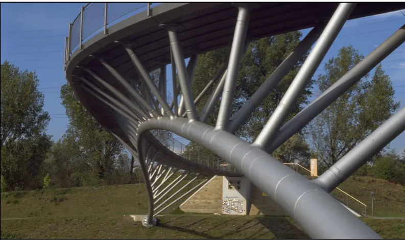
Fig 1.1. Ripshorster Bridge, Germany ... 33
Fig 1.2. Kansai International Airport in Osaka, Japan ... 33
Fig 1.3. University House at the University of Warwick, UK ... 33
Fig 1.4. An under-construction frame composed of steel I-beams connected to circular CFT columns with external diaphragm plates ... 35
Fig 2.1. Internal diaphragm joint ... 41
Fig 2.2. Through diaphragm joint ... 41
Fig 2.3. External diaphragm joint ... 41
Fig 2.4. Type–I joint with flared plates ... 48
Fig 2.5. Type–II joint with external diaphragms ... 48
Fig 2.6. Side view of the failure of joint Type–I: weld and flange fracture ... 50
Fig 2.7. Top view of the failure of joint Type–II: diaphragm and column wall fractures ... 50
Fig 2.8. Front view of the failure mode of joints made with RBS beams ... 54
Fig 2.9. Front view of the failure mode of joints made with the minimum width ring ... 54
Fig 2.10. Top view of the exterior 3D joint to CHS column stiffened with external diaphragms ... 55
Fig 2.11. Front view of the exterior 3D joint to CHS column stiffened with external diaphragms ... 55
9
Fig 3.1. The components of the beam to column joint before assembly... 65
Fig 3.2. The beam to column joint after assembly ... 65
Fig 3.3. Moment of the joint in relation to the beam moment ... 81
Fig 3.4. Widths of different sections in the DP ... 90
Fig 3.5. Design assumption for the DP ring according to Wang et al. (2011) ... 93
Fig 3.6. Web stub subject to shear force ... 96
Fig 3.7. Block tearing of the web plate ... 99
Fig 4.1. General shape and geometry of the tensile coupons ... 114
Fig 4.2. Attachments of the displacement transducer to a tensile coupon ... 117
Fig 4.3. Instrumentation of tensile coupon tests ... 117
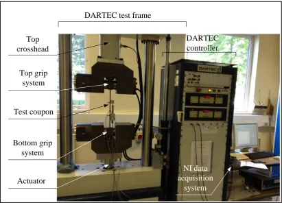
Fig 4.4. A tensile coupon test using the DARTEC 9500 testing facility ... 119
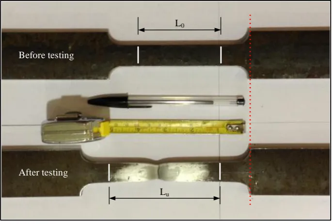
Fig 4.5. A tensile coupon before and after testing ... 120
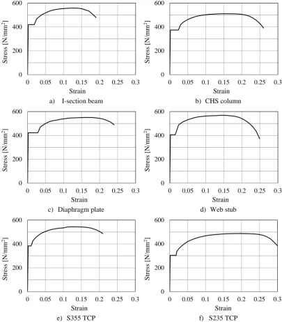
Fig 4.6. Average engineering stress-strain curves of the joint components ... 121
Fig 5.1. The column assembly ... 125
Fig 5.2. Photographs of the weld work in the column assembly ... 126
Fig 5.3. Details of the fillet welds in the column assembly ... 126
Fig 5.4. Details of the FPB welds in the column assembly ... 127
Fig 5.5. Details of the fillet welds in the beam assembly ... 128
Fig 5.6. Geometry of the beam stiffener ... 128
Fig 5.7. A photograph of the weld work in the beam assembly ... 128
Fig 5.8. A tapered cover plate assembly and its weld details ... 129
Fig 5.9. Bolt tightening process ... 130
Fig 5.10. Test specimen assembled inside the test rig ... 130
Fig 5.11. 3D illustration of the swivel hinges and their components ... 131
Fig 5.12. Function of the swivel hinges... 132
Fig 5.13. Schematic arrangement of the test rig ... 133
Fig 5.14. Schematic arrangement of the lateral supports for the I-beam ... 134
Fig 5.15. Photographs of the lateral support arrangement for the I-beam ... 134
10
Fig 5.17. Photograph of the column bottom hinge ... 136
Fig 5.18. The digital calliper ... 137
Fig 5.19. The Ball-Micrometer ... 137
Fig 5.20. Geometry measurements of the I-section beam ... 138
Fig 5.21. Geometry measurements of a diaphragm plate ... 141
Fig 5.22. Geometry imperfection measurements of the I-beam ... 142
Fig 5.23. Geometry imperfection measurements of the I-beam top flange ... 143
Fig 5.24. Calculation of the actuator displacements for the loading protocol ... 146
Fig 5.25. Displacement-controlled loading cycles ... 147
Fig 5.26. Calibration of the actuator load cell in tension ... 149
Fig 5.27. Sketch of the column web panel zone and its strain gauges ... 151
Fig 5.28. Location of strain gauges on the column web panel zone ... 151
Fig 5.29. Sketch of the two diaphragm plates and their strain gauges ... 152
Fig 5.30. Location of strain gauges on the top diaphragm plate ... 153
Fig 5.31. Location of strain gauges on the bottom diaphragm plate ... 154
Fig 5.32. Sketch of two unstiffened TCPs and their strain gauges ... 154
Fig 5.33. Location of strain gauges on a top unstiffened TCP ... 155
Fig 5.34. Location of strain gauges on a bottom unstiffened TCP ... 155
Fig 5.35. Top and 3D views of two stiffened TCPs and their SGs ... 156
Fig 5.36. Location of strain gauges on top and bottom TCP stiffeners ... 156
Fig 5.37. Location of strain gauges on a top stiffened TCP ... 157
Fig 5.38. Location of strain gauges on a bottom stiffened TCP ... 157
Fig 5.39. Location of strain gauges on the I-section beam ... 157
Fig 5.40. Sketch of the test specimen detailing the location of INCs ... 158
Fig 5.41. Fixing arrangement of INC–1 to the column web panel ... 159
Fig 5.42. Fixing arrangements of INC–2 and INC–4 to the specimen front face ... 160
Fig 5.43. Fixing arrangement of INC–3 to the back face of the beam web ... 161
Fig 5.44. Calibration of inclinometers ... 163
Fig 5.45. Location of displacement transducers (DTs) on a test specimen ... 164
Fig 5.46. Fixing arrangements of DT–1 and DT–4 ... 166
Fig 5.47. Fixing arrangement of DT–2 and DT–3 viewed from different angles ... 166
Fig 5.48. Locations of DT–5, DT–6, DT–7 and DT–8 on a test specimen ... 168
11
Fig 5.50. Calibration of displacement transducers ... 170
Fig 5.51. The measurement hardware modules from National Instruments ... 172
Fig 5.52. The front panel of the testing program ... 173
Fig 6.1. Load–strain curves of the column web panel in Tests 1–9 ... 177
Fig 6.2. Local deformation of the column web panel in Tests 1–9 ... 179
Fig 6.3. Local deformation of the web stub in Tests 1–9 ... 181
Fig 6.4. Load–strain curves of the I-beam critical section in Tests 1–9 ... 183
Fig 6.5. Moment-rotation curves of the I-beam in Tests 1–9 ... 186
Fig 6.6. Load–strain curves of the diaphragm plates in Tests 1–9 ... 189
Fig 6.7. Load–strain curves of the tapered cover plates in Tests 1–9 ... 191
Fig 6.8. Buckling of the top TCP in Test–6: S235-NSH-NS-FP ... 192
Fig 6.9. Normalised moment-rotation curves of the joint in Tests 1–9 ... 195
Fig 6.10. Normalised moment-rotation curves of the plastic hinge region ... 197
Fig 6.11. Stiffness classification of the joint in Tests 1–9 ... 200
Fig 6.12. Accumulated energy dissipation in Tests 1–9 ... 201
Fig 6.13. Accumulated energy dissipation beyond the 25th cycle in Tests 1–9 ... 202
Fig 6.14. Steel grade comparison between the results of Test–1 and Test–4 ... 204
Fig 6.15. Steel grade comparison between the results of Test–2 and Test–5 ... 205
Fig 6.16. Steel grade comparison between the results of Test–6 and Test–7 ... 206
Fig 6.17. Use of stiffeners comparison between the results of Test–1 and 2 ... 208
Fig 6.18. Use of stiffeners comparison between the results of Test–6 and 3 ... 209
Fig 6.19. Use of stiffeners comparison between the results of Test–4 and 5 ... 211
Fig 6.20. Size of holes comparison between the results of Test–1 and 6 ... 212
Fig 6.21. Size of holes comparison between the results of Test–2 and 3 ... 213
Fig 6.22. Size of holes comparison between the results of Test–4 and 7 ... 215
Fig 6.23. Preloading force comparison between the results of Test–1 and 8 ... 217
Fig 6.24. Preloading force comparison between the results of Test–5 and 9 ... 219
Fig A.1. Block diagram of the main joint-test programme in LabVIEW ... 247
12
Fig A.3. Block diagram detail – Data acquisition function ... 248
Fig A.4. Block diagram detail – Recalling the sub-programme “Calibration” ... 249
Fig A.5. Block diagram detail – Producing a plot in LabVIEW ... 249
Fig A.6. Block diagram detail – Saving calibrated measurements to a file ... 250
Fig B.1. Moment-rotation curves of the column hinges in Tests 1–9 ... 253
Fig C.1. Elastic rotation of a cantilever at a given section... 255
13
List of Tables
Table 3.1. Geometry and properties of the joint components ... 69
Table 3.2. Tests label according to the type of TCPs used in the test specimens .... 72
Table 3.3. Design tension resistance of the TCPs ... 76
Table 3.4. The joint moment at full plasticity of the TCPs middle sections ... 80
Table 3.5. Spacing, end and edge distances for the TCP to the beam connection .. 85
Table 3.6. Spacing, end and edge distances for the TCP to the DP connection ... 95
Table 3.7. Spacing, end and edge distances for the web connection ... 101
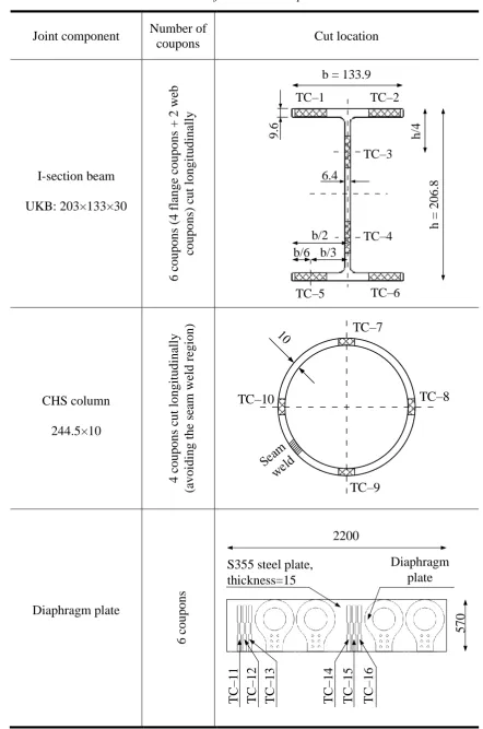
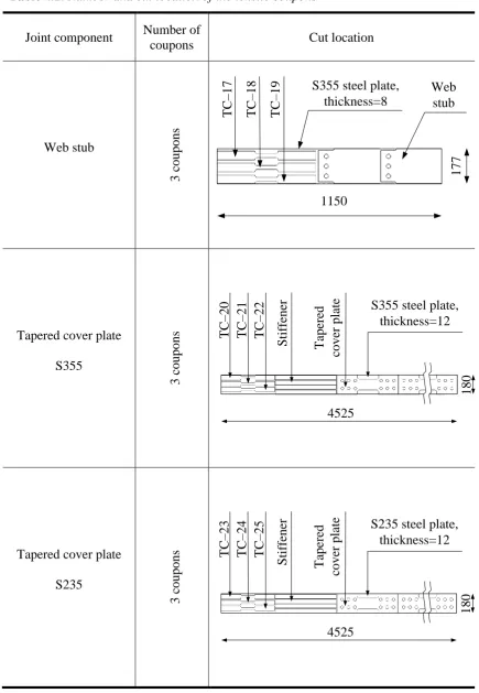
Table 4.1. Number and cut location of the tensile coupons ... 112
Table 4.2. Detailed dimensions of the tensile coupons ... 115
Table 4.3. Strain rates and crossheads separation velocities for the TC tests ... 119
Table 4.4. Key results from the tensile coupon tests ... 122
Table 5.1. Geometry measurements of UKB 203×133×30 ... 138
Table 5.2. Tolerance on the measured dimensions of UKB 203×133×30 ... 139
Table 5.3. Geometry measurements of the CHS column ... 140
Table 5.4. Geometry measurements of the diaphragm plates ... 140
Table 5.5. Geometry measurements of the web stub ... 141
Table 5.6. The I-beam out-of-squareness measurements ... 144
Table 5.7. The major-axis out-of-straightness measurements of the I-beam ... 145
14
Table 5.9. Instruments connections to the NI hardware modules ... 172
Table 6.1. The number of completed loading cycles for the nine joint tests ... 175
Table 6.2. The main response parameters obtained from the nine joint tests ... 193
Table 6.3. Maximum rotation of the plastic hinge region in the nine joint tests ... 198
Table 6.4. Initial rotational stiffness of the joint in Tests 1-9 ... 199
15
Acknowledgments
This research was carried out under the supervision of Dr Tak-Ming Chan whose
great knowledge, patience and motivation have guided me throughout the course of
my research until the completion of this doctoral thesis. I would like to express my
sincere gratitude and appreciation to Dr Tak-Ming Chan for all the support he has
given me on both the academic and personal levels during this journey. This work
would have not been completed without his invaluable advice and great expertise.
I would like also to thank Dr Ken Mao for being my supervisor during the last few
months of my PhD course. I had the privilege to do my Master’s degree under his
supervision a few years ago and I am very thankful for having had another chance to
benefit from his invaluable support and advice.
I am very thankful to Prof Toby Mottram and Prof Leroy Gardner who examined my
PhD viva and gave me their honest and invaluable feedback. I would also like to
thank Prof Mottram for allowing me to benefit from his great knowledge and
technical expertise whenever I approached him with a question during my PhD
course.
I am indeed grateful to Damascus University in Syria for their financial support,
16 School of Engineering at the University of Warwick for their financial awards. The
technical support from the Structures Laboratory at the University of Warwick is
gratefully acknowledged. I would like to thank in particular Mr Juan Munoz Leal
who put a lot of time and effort into the preparation and conducting of the project
laboratory experiments, and has been also a great friend I am very lucky to have met.
Beyond Engineering, I would like to thank all my close friends who had sometimes
to tolerate my mood swings and never stopped being supportive or amazing. I would
like to thank Dr Sotiris Paraschas for the great times we have had together; Selina
Moutia for being so supportive, loving and caring; Dr Ahmad Issa for always being
there for me; Dr Lena Al Khudairy for being my best friend and confidante; Kahtan
Almahmoud for the great friendship we have had together since our childhood; and
to Marcus Cross, I doubt there will be enough words to express how thankful I am
for all the support you have given me, for believing in me and sharing with me my
best and worst moments.
Last but not least, I would like to thank my family without whom I would not be
where I am today. To my mother Wafaa Sulaiman and my father Sami Al Khadour, I
lose words in front of your unconditional love and support. I hope I can keep you
always proud of me and give back to you some of the endless kindness you have
shown me. To My brother Dr Ebrahim Al’Khadour, thank you for being my
backbone and making me a stronger person. To my sister Dr Sarah Khadour, thank
you for being a caring sister and a faithful friend; and to my beautiful princess and
little sister, Leen Al’Khadour, I am so proud of being your brother, thank you for
drawing a smile on my face at all times.
17
Declaration
This thesis is submitted to the University of Warwick in support of my application
for the degree of Doctor of Philosophy in Structural Engineering. It has been
composed by myself and has not been submitted in any previous application for any
degree.
The work presented (including data generated and data analysis) was carried out all
by myself unless otherwise stated. The theoretical planning of the joint design, test
loading protocol and instrumentation were derived from collaborative work with Dr
Alireza Bagheri Sabbagh during his employment as a Research Fellow at the School
of Engineering, University of Warwick.
The parts of the thesis, which have been published (or submitted for publication) by
me as a first author during the period of my study for this degree, are detailed in the
“Scientific Outcomes” section in the “Conclusions” Chapter of this thesis.
18
Summary
Tubular columns own many structural and architectural advantages that, in certain
cases, make them more favourable than open-section columns in steel
moment-resisting frames. These advantages are sometimes underexploited due to the relative
lack of design guidance on their moment joints to open-section beams, in particular
on semi-rigid joints with special detailing for seismic actions. Different
configurations of I-beam to tubular column joints have been investigated in the past,
including through, internal and external diaphragm joints. This project investigates
experimentally the cyclic behaviour of an external diaphragm joint between a steel
I-beam and a circular hollow section column. The proposed joint includes two
diaphragm plates (DPs) welded to the outer circumference of the column and bolted
to the I-beam flanges with two tapered cover plates (TCPs). A web stub is welded to
the column face and bolted to the I-beam web. Full-scale laboratory experiments
were conducted to investigate the hysteretic response and energy dissipative
performance of the proposed joint under cyclic loading. TCPs were integrated in the
joint to act as replaceable sacrificial components that dissipate most of the energy
whilst the rest of the joint components remain elastic to minimise the post-seismic
repair. The test specimens were identical except their TCPs that had the same
geometry but differed in steel grade, size of bolt-holes, use of stiffeners or bolt
preloading force. The use of higher grades of steel for the TCPs and stiffening them
imposed higher strain demands in the beam and DPs and dissipated less energy than
the joints with lower grades and unstiffened TCPs, respectively. The results
confirmed that the main energy dissipation fuse in these joints was yielding in the
TCPs while the other components remained elastic. Connection slippage created a
second fuse for energy dissipation when the bolt preloading force was properly
controlled, and the rotation of the plastic hinge region exceeded the minimum
19
Symbols
a Effective throat thickness of fillet weld
A Percentage elongation after fracture for a tensile-testing piece
a0 Original thickness of a tensile-testing piece
Ab Gross cross section area of a bolt
Abeam Area of the I-beam cross section
Ac Area of the CHS column cross section
ADP,cf Area of the DP cross section at the column face
ADP,r Area of the cross section of the DP ring
ADP,rec Area of the DP rectangular cross section
Af Area of the I-beam flange
Agr Area of the gross section
Anet Area of the net cross-section at holes for bolts
Ant Net area subject to tension
Anv Net area subject to shear
Ared Area of the reduced section of the TCP
As Tensile stress area of a bolt
Av Shear area of the I-beam
20 Aw Area of the I-beam web
Awpl Area of the web plate cross section
b Width of the I-beam cross section
B Width of a tensile-testing piece
b0 Original width of the parallel length of a tensile-testing piece
c Width or depth of a part of a cross section
d Nominal bolt diameter
d0 Bolt-hole diameter
D0 External diameter of the CHS column
d0,bw Bolt-hole diameter in the I-beam web
d0,wpl Bolt-hole diameter in the web plate
da Vertical displacement of the actuator
E Modulus of elasticity
e1 End distance from the bolt hole centre to the adjacent end of the
connected part in a line in the direction of load transfer
e2 Edge distance from the bolt hole centre to the adjacent edge of the
connected part measured in a line perpendicular to the load transfer
direction
Ebeam Modulus of elasticity of the I-beam steel
eM1 Eccentricity of the design shear force of the web connection with
respect to the web plate edge
eM2 Eccentricity of the design shear force of the web connection with
respect to the column face
Fb,Rd,min Minimum design bearing resistance of an individual bolt
21
Fbf,end,b,Rd Design bearing resistance of an end bolt in the I-beam flange
Fbf,inner,b,Rd Design bearing resistance of an inner bolt in the I-beam flange
Fbw,end,b,Rd Design bearing resistance of an end bolt in the I-beam web
Fbw,inner,b,Rd Design bearing resistance of an inner bolt in the I-beam web
FDP,end,b,Rd Design bearing resistance of an end bolt in the DPs
FDP,inner,b,Rd Design bearing resistance of an inner bolt in the DPs
Fp,Cd Preload force of a bolt
FRd,min Minimum design resistance of an individual bolt
Fs,Rd Design slip resistance of a connection
FTCP,b,Rd Design bearing resistance of a single bolt in the TCPs
FTCP,end,b,Rd Design bearing resistance of an end bolt in the TCPs
FTCP,inner,b,Rd Design bearing resistance of an inner bolt in the TCPs
fu Ultimate strength
fu,beam Ultimate strength of the I-beam steel
fu,c Ultimate strength of the CHS column steel
fu,DP Ultimate strength of the diaphragm plate steel
fu,TCP Ultimate strength of the TCP steel
fu,w Ultimate strength of the fillet weld
fu,ws Ultimate strength of the web stub steel
fub Ultimate tensile strength of a bolt
Fv,Rd Design shear resistance of a single bolt
fvw.d Design shear strength of weld
Fw,Ed Design value of the weld force per unit length
Fw,Rd Design weld resistance per unit length
22
Fws,inner,b,Rd Design bearing resistance of an inner bolt in the web stub plate
fy Yield strength
fy,beam Yield strength of the I-beam steel
fy,c Yield strength of the CHS column steel
fy,DP Yield strength of the diaphragm plate steel
fy,TCP Yield strength of the TCP steel
fy,wp Yield strength of the column web panel steel
fy,ws Yield strength of the web stub steel
fyb Yield strength of a bolt
h Depth of the I-beam cross section
hs Height of the TCP stiffener
hw Depth of the I-beam web
hwpl Height of the web plate
hws Height of the gross section of the web stub
Iwpl Second moment of area of the web plate cross section about its major
axis
Iy Second moment of area about the major axis of a cross section
k Out-of-squareness of the I-beam bottom flange
k' Out-of-squareness of the I-beam top flange
ks Factor depending on bolt hole size
L0 Original gauge length of a tensile-testing piece
Lc Length of the parallel reduced section of a tensile-testing piece
Lcc Distance between the loading point and the column centre
23 Lcr Length of the I-beam between the centre of the loading application
area and the beam critical section
LDP,rec Distance between the loading point and the critical cross section of
the rectangular part of the DP
Le Initial displacement transducer gauge length
Leff Effective length of the I-beam between the centre of the loading
application area and the beam connected end
Lt Total length of a tensile-testing piece
Lu Length between gauge length marks on a tensile-testing piece after
rupture
Lw Total length of fillet weld
Lw,eff Effective length of fillet weld
M2 Moment calculated at the location of INC–2
M4 Moment calculated at the location of INC–4
M5 Moment calculated at the location of INC–5
Mb,el,y,Rd Design elastic bending resistance of the I-beam cross section
Mb,pl,y,Rd Design plastic bending resistance of the I-beam cross section
Mc,el,y,Rd Design elastic bending resistance of the CHS column cross section
Mcc,ED Design bending value at the column centre
Mcf Moment at the column face
Mj Moment of joint
Mj,b,el Joint moment when the beam critical section reaches its design
elastic bending resistance
Mj,b,pl Joint moment when the beam critical section reaches its design
24
Mj,max Maximum moment of the joint calculated at the connected end of the
I-beam
Mj,pl Joint moment when the reduced section areas of the TCPs (and their
stiffeners when applicable) reach full plasticity
Mw,ED Design bending value at the fillet weld cross section
Mwpl,ED Design bending value in the web plate
Mwpl,el,RD Design elastic bending resistance of the web plate cross section
n Number of friction planes
N Number of bolts in a connection
NDP,cf,t,Ed Design tension value in the DP cross section at the column face
NDP,cf,t,Rd Design tension resistance of the DP cross section at the column face
NDP,r,t,Rd Design tension resistance of the cross section of the DP ring
NDP,rec,t,Ed Design tension value in the DP rectangular cross section
NDP,rec,t,Rd Design tension resistance of the DP rectangular cross section
Npl,Rd Design plastic resistance of the gross section
Nred,pl,Rd Design plastic resistance of the reduced cross section of the TCP
NTCP,t,Rd Design tension resistance of the TCP cross section
Nu,Rd Design ultimate resistance of the net cross-section at holes for bolts
Nw Number of fillet weld lines
P Vertical load acting on the free end of a cantilever
P1 Spacing between centres of bolt holes in a line in the direction of load
transfer
P2 Spacing between centres of bolt holes in a line perpendicular to the
load transfer direction
25 r Root radius
S Leg size of fillet weld
S0 Original cross-section area of the parallel length of a tensile-testing
piece
Sj,ini Initial rotational stiffness of a joint
Swpl First moment of area of the web plate section above its major axis
tc Thickness of the CHS column wall
tDP Thickness of the diaphragm plate
tf Thickness of the I-beam flange
ts Thickness of the TCP stiffener
tTCP Thickness of the TCP
tw Thickness of the I-beam web
tws Thickness of the web stub
Vbw-ws,Rd Design resistance of the web connection
VEd Design shear value
Veff,1,Rd Design block tearing resistance
Vel,Ed Design shear value in the I-beam at yield onset in its critical section
Vel,Rd Design elastic shear resistance
Vpl,Rd Design plastic shear resistance
VTCP-bf,Rd Design resistance of the TCP-beam connection
VTCP-bf,v,Ed Design shear value in the TCP-beam connection
VTCP-bf,v,Rd Design shear resistance of the TCP-beam connection
VTCP-DP,Rd Design resistance of the TCP-DP connection
VTCP-DP,v,Ed Design shear value in the TCP-DP connection
26
Vwp,Ed Design shear value in the column web panel
Vwp,Rd Design plastic shear resistance of the column web panel
Vwpl,el,Rd Design elastic shear resistance of the web plate cross section
Vwpl,pl,Rd Design plastic shear resistance of the web plate cross section
Wc,el,y Elastic section modulus of the CHS column cross section about its
major axis
Wc,pl,y Plastic section modulus of the CHS column cross section about its
major axis
WDP,cf Width of the diaphragm plate at the column face
WDP,fe Width of the diaphragm plate flat end
WDP,r Width of the diaphragm plate ring
Wel,y Elastic section modulus about the major axis
Wpl,y Plastic section modulus about the major axis
Wred Width of the reduced section area of the TCP
WTCP Width of the TCP
Ww,el,y Elastic section modulus of the fillet weld cross section about its major
axis
Wwpl,el,y Elastic section modulus of the web plate cross section about its major
axis
y-y Major axis
z1 Lever arm between the coupling forces acting on the centroids of the
top and bottom TCPs cross sections
z2 Lever arm between the coupling forces acting in the shear planes of
27 z3 Lever arm between the coupling forces acting on the top and bottom
DPs cross sections
αb,end Factor αb for an end bolt
αb,inner Factor αb for an inner bolt
βw Correlation factor for fillet welds
γM0 Partial safety factor
γM2 Partial safety factor
γM3,ser Partial safety factor for serviceability limit state
γov Material overstrength factor
ε Factor depending on fy
εbeam Strain in the beam
εc Strain in the column
εDP Strain in the diaphragm plate
εmax,beam Maximum strain observed in the I-beam during a test
εmax,DP Maximum strain observed in the diaphragm plates during a test
εsh Work-hardening strain
εTCP Strain in the tapered cover plate
εu Ultimate strain
εy Yield strain
εy,beam Yield strain of the I-beam steel
εy,c Yield strain of the CHS column steel
εy,DP Yield strain of the diaphragm plates steel
εy,TCP Yield strain of the tapered cover plates steel
η Factor for shear area
28 θ1 Rotation measurement from INC–1
θ2 Rotation measurement from INC–2
θ3 Rotation measurement from INC–3
θ4 Rotation measurement from INC–4
θ5 Rotation measurement from INC–5
θb Rotation at the beam section located 200mm from the connection end
θb,crit Rotation at the beam critical section (at the connection end)
θc,h Rotation of the column end hinges
θdr Interstory drift angle
θel Angle of elastic rotation of the beam
θp Rotation of the plastic hinge region
θp,DCM Minimum rotation capacity of the plastic hinge region for structures
of medium ductility class (DCM)
θp,max Maximum rotation of the plastic hinge region
θwp Rotation of the web panel
θws Rotation of the web stub
μ Slip factor
σ┴ Normal stress perpendicular to the fillet weld throat
τ║ Shear stress in the plane of the fillet weld throat and parallel to the
axis of the weld
τ┴ Shear stress in the plane of the fillet weld throat and perpendicular to
the axis of the weld
τEd Design value of the local shear stress
29
Abbreviations
2D Two-dimensional
3D Three-dimensional
AIJ Architectural Institute of Japan
AISC The American Institute of Steel Construction
BSI British Standards Institution
CFT Concrete filled tube
CHS Circular hollow section
CJP Complete joint penetration weld
COV Coefficient of Variation
DCH High ductility class
DCM Medium ductility class
DP Diaphragm plate
DT Strain gauge displacement transducer
EC Eurocode
ECCS The European Convention for Constructional Steelwork
FE Finite element
FEMA Federal Emergency Management Agency
30 FPB Full penetration butt weld
HP Bolts are preloaded to half the value in Eurocode 3: Part 1–8
HSFB High strength friction bolt
INC Inclinometer
LSP Lateral support plate
NI National Instruments corporation
NS No stiffeners for the tapered cover plates
NSH Normal-size holes
OSH Oversized holes
PTFE Polytetrafluoroethylene – a synthetic material that has a very low
coefficient of friction
RBS Reduced beam section
SG Strain gauge
SLS Serviceability Limit State
SMF Special moment frame
SSoW Safe system of work
TC Tensile coupon
TCP Tapered cover plate
VS Vertical stiffener
31
Chapter 1
Introduction
This chapter presents an overview of the advantages of hollow sections, the aims and
objectives of this research and the outline of the thesis. The definitions of
connections and joints in this thesis follow those given in Clauses 1.4.2 and 1.4.4 in
BS EN 1993-1-8: 2005, where a single-sided beam-to-column joint consists of the
32
1.1.
Advantages of hollow sections
Structural hollow (tubular) sections possess many structural and architectural
advantages due to their closed geometry. Their aesthetically pleasing profiles have
offered architects a great alternative to use in structures with visible steel sections. In
structures where steel sections are exposed to high humidity and aggressive
atmosphere, those made with tubular sections require less protection against
corrosion and have a longer corrosion protection life than comparable structures
made with open sections. This is due to the round corners of hollow sections, the
absence of sharp edges and having smaller surfaces exposed to corrosion than those
in comparable open sections {Mesquita et al. (2009); Wardenier et al. (2010)}.
Furthermore, tubular sections, especially circular hollow sections, are favoured in
offshore structures because of their lower drag coefficients in comparison to open
sections. Another advantage of structural tubular sections is that their internal void
may be used to incorporate ventilation systems or to be filled with concrete.
Concrete filled tubes (CFT) have higher compression resistance and enhanced fire
resistance duration than their hollow counterparts {Wardenier et al. (2010)}. Tubular
sections have been used in various structural applications; such as buildings, bridges,
halls and offshore structures. Figures 1.1 to 1.3 show a few examples of structures
made with hollow sections {Wardenier et al. (2008) and (2010)}.
Circular, square and rectangular hollow sections (CHS, SHS and RHS respectively)
have been the most common tubular sections in structural applications. New tubular
shapes are becoming more popular recently such as elliptical hollow sections (EHS),
33 emerged from recent research studies such as {Ruiz-Teran and Gardner (2008);
Chan and Gardner (2010); Gardner et al. (2011)}.
Figure 1.1: Ripshorster Bridge, Germany
Figure 1.2: Kansai International Airport in Osaka, Japan
Figure 1.3: University House at the University of Warwick, UK
In terms of design resistances, hollow sections are very efficient with respect to their
torsional stiffness and bending in both directions because of their relatively high
moment of area and section modulus about the minor axis in comparison to their
open-section counterparts, {Kurobane et al. (2004); Chan and Gardner (2008);
[image:34.595.119.516.136.371.2]34 The use of structural hollow sections in columns has many other advantages over
open sections of the same section size, such as higher compression resistance
{Mesquita et al. (2009)}. This is because the radius of gyration about the minor axis
is higher for hollow sections and subsequently their slenderness ratio is lower than
that of a similar size and similar effective length open section column. In addition to
that, residual stresses resulting from the manufacturing process are usually
distributed in hot-rolled hollow sections in a more favourable way than that in open
sections due to the geometrical characteristics of the former {Kurobane et al.
(2004)}. Finally, structural hollow sections are generally produced in long lengths,
up to 20m, that enable, where applicable, the use of one length per column for the
total height of a building {Kurobane et al. (2004)}.
Overall, open sections are more economical than hollow sections when they are
subject to bending about the major axis because the unit material of tubular columns
is more expensive than that of open sections. However, in cases when the design
bending resistance of the section is largely reduced by lateral buckling or when
bending about both axes is present, hollow sections offer a better weight-to-strength
ratio than open sections. Hence, through proper design, the use of hollow sections
could result in more cost effective moment frames {Kurobane et al. (2004);
Elghazouli et al. (2009); Wardenier et al. (2010)}.
These structural and architectural advantages of tubular columns are sometimes
underexploited due to the relative lack of design guidance on moment joints between
open-section beams and tubular columns, and in particular the design of semi-rigid
joints with special detailing for seismic actions. Figure 1.4 shows a composite frame
I-35 beams joined together by external diaphragm connections. More details about
previous research on moment joints to tubular columns are presented in Chapter 2.
Figure 1.4: An under-construction frame composed of steel I-beams connected to circular CFT columns with external diaphragm plates {Han et al. (2011)}
1.2.
Aims and objectives of this project
The main aim of this project is to develop an I-beam to CHS column joint that is
architecturally appealing, practical for construction and most importantly achieves
the required structural performance and ductility under seismic loading for
dissipative structures (moment resisting frames for this project). Furthermore, the
joint should enable having no permanent deformations in the primary members of
the moment-resisting frame to minimise the operations and time of repair for
post-seismic damages of the structure.
External Diaphragm plates
Steel I-beam
36 The Federal Emergency Management Agency (FEMA) in the United States of
America published the FEMA-356 (2000) report, prepared by the American Society
of Civil Engineers, on the seismic rehabilitation of buildings. In this report, the
structural performance of buildings was classified according to post-earthquake
damages into four different levels and two intermediate ranges. The structural
performance of buildings in FEMA-356 report ranges from the level of immediate
reoccupancy of the structure after a seismic event, to the collapse prevention level, at
which the building continues to support gravity loads but is not safe for reoccupancy
and the required repair of the damages may not be practical nor economical because
the structure is on the verge of partial or total collapse.
This project aims at designing joint detailing that allows the investigated
moment-resisting frame to be classified in the Damage Control Structural Performance range,
in which the post-seismic repair operations are required, yet are minimal to provide
quick reoccupancy of the building. To achieve this, the proposed joint incorporates
built-in replaceable links that dissipate most of the seismic energy and act as
sacrificial components to be easily replaced after a seismic event, whilst the rest of
the joint components remain elastic. Different types of the replaceable links were
investigated in the experimental programme because of their influence on the overall
seismic performance of the joint.
1.3.
Outline of thesis
This thesis contains seven chapters with the main contents as follows;
Chapter 1 gives a brief introduction on the advantages of hollow sections, the
37
Chapter 2 is a review of relevant literature with a particular focus on steel joints
made with external diaphragm plates.
Chapter 3 presents the design philosophy adopted at the design stage of the
project, the details of the proposed joint and the design calculations for the joint
components.
Chapter 4 reports the tensile coupon tests conducted to characterise the different
joint components and the key results.
Chapter 5 presents all the preparations that were carried out in the Structures
Laboratory for the full-scale experimental program. It scopes the preparation of
the test specimens, the test rig, the geometry and geometry imperfection
measurements, the loading protocol and the instrumentation plan.
Chapter 6 presents in its first section the tests results obtained from the full-scale
laboratory experiments. The second section of the chapter covers a detailed
parametric comparison study between the different tests results.
Chapter 7 is used to summarise the research and present the key findings and
limitations. Suggestions for future work and the scientific outcomes of the PhD
38
Chapter 2
Literature Review
2.1.
Introduction
This chapter presents a review of relevant literature on the subject of joints to tubular
columns in moment-resisting frames with additional emphasis on frames having
CHS columns with external diaphragm joints designed for seismic loadings. Firstly,
a brief overview of different configurations of moment joints to tubular columns is
presented. Then, a more focused review of experimental, numerical and analytical
39
2.2.
Moment joints to tubular columns
In steel moment-resisting frames, open I-section beams are the most commonly used
due to their efficiency in resisting bending about their major axis, while the columns
can have either open or tubular sections. As mentioned in the Chapter 1, tubular
columns have many structural and architectural advantages over open-section
columns. Nonetheless, these advantages are sometimes underexploited due to the
relative lack of design guidance on moment joints between open-section beams and
tubular columns, and in particular the design of semi-rigid joints with special
detailing for seismic actions.
Research studies on moment joints to hollow section columns have varied depending
on the column shape and desired performance of the joint. There seems to be
relatively fewer studies on moment joints to circular hollow section columns in
comparison to their square and rectangular counterparts. This could be due to facing
more difficulties in detailing joints to the curved surface of CHS columns than that
to the flat faces of SHS or RHS columns.
Moreover, most of these studies have focused on joints to concrete filled tubes
(CFT) rather than joints to unfilled hollow section columns. CFT columns combine
the advantages of ductile steel and stiff concrete. The concrete restrains local
buckling of the steel tube, while the steel tube eliminates the need of construction
framework, acts as longitudinal reinforcement to the concrete and provides its lateral
confinement {Bergmann et al. (1995); Alostaz and Schneider (1996); Fukumoto and
Morita (2005); Wu et al. (2007); Shin et al. (2008)}. References to previous studies
on joints to CFT columns are only for those configurations that can be applied to
40 Conventional configurations of semi-rigid bolted joints to open-section columns
were examined for tubular columns as well. The closed geometry of hollow sections
limits access to their outer walls only, and hence fastening techniques that do not
require access to the columns inner wall were crucial to the fabrication of such
joints. Connections made using the flowdrill system, which is a thermal drilling
technique used for the extrusion of holes in a tubular column wall, were investigated
by France et al. (1999) and (1999a). The blind-bolting system, which involves the
use of modern bolts provided with a built-in interlock mechanism that activates when
they are tightened, is another technique employed in recent years to join open-beams
to tubular/CFT columns using bolted angle, flush end plate or extended end plate
connections {Elghazouli et al. (2009); Mesquita et al. (2009) and (2010); Wang et
al. (2013)}. Reverse channel connections, in which a reverse channel is welded to
the column skin and bolted to the beam with angles or an end plate, were proposed in
the work of Liu and Wang (2009) and Málaga-Chuquitaype and Elghazouli (2010) as
a practical and cost-effective alternative for joining I-section beams to SHS/CHS
columns in moment resisting frames.
The width of an open-section beam that frames into a tubular column is usually less
than the column width. Previous research studies revealed that joints made by
welding open-section beams directly to the outer skin of tubular columns without the
use of any stiffeners were not suitable for seismic applications because they
exhibited, under cyclic loading, unfavourable stiffness and strength characteristics
and significant distortions of the tube wall, which prevented plastic hinging of the
beam and led to brittle failures of the weld and the beam flanges {Alostaz and
41 Reinforcing the column at the levels of the beam flanges with stiffeners, which act
similarly to continuity plates in open-section columns, was, when properly designed,
found to increase the shear resistance of the column web panel and transfer the axial
forces from the beam flanges to the column more efficiently {Kurobane et al.
(2004); Wang et al. (2011)}. Figures 2.1 to 2.3, taken from the Foolad Machine
company website, show the general details of three conventional joints to tubular
columns employing internal, through and external stiffeners (diaphragm plates)
respectively. These joints have been used in the design of moment-resisting frames
mainly in Japan and some other Asian countries such as China and Korea.
Figure 2.1: Internal diaphragm joint, taken
from Foolad-Machine company website www.fooladmachine.com
Figure 2.2: Through diaphragm joint, taken
from Foolad-Machine company website www.fooladmachine.com
Figure 2.3: External diaphragm joint, taken from Foolad-Machine company website
42 Internal diaphragm joints, in which the tube is usually cut in one location and
continuity plates are welded around its inside wall at the position of beam flanges,
have been investigated by many researchers {Chen et al. (2004); Ricles et al. (2004);
Cheng et al. (2007); Wang et al. (2014)}. The fabrication of such arrangement is not
simple nor cost effective because it requires extensive welding work and skilled
welders to eliminate frequently detected weld defects of these joints {Alostaz et al.
(1997); Ricles et al. (2004); Kurobane et al. (2004)}.
Through diaphragm joints, in which the tube is cut in two locations and its three
pieces are welded to two diaphragm plates that themselves are welded or bolted to
the beam flanges, were also investigated {Nakashima et al. (1998); Cheng and
Chung (2003); Nishiyama et al. (2004); Kurobane et al. (2004); Jiao et al. (2011);
Qin et al. (2014)}. The use of through diaphragm plates was found to transfer axial
loads from the beam flanges into the column web in a simple manner and increase
the strength and stiffness of the joint. Nevertheless, this arrangement discontinues
the column and requires a lot of welding work that results in higher risks of weld
defects. Furthermore, this arrangement is not practical when the beams framing into
a column are of different depths. In spite of these weaknesses, the use of welding
robots and other suitable production resources have made through diaphragm joints
the most popular arrangement for joining I-beams to tubular columns in Japan
{Kurobane et al. (2004); Wang et al. (2011)}.
The difficulties and risks associated with internal and through stiffening of tubular
columns increased the necessity of finding efficient designs of external stiffeners.
Different shapes of outer stiffeners and external diaphragm plates have been
examined during the last two decades. The use of external diaphragm plates allows
43 costs and provide structural integrity between the beam and the column {Alostaz and
Schneider (1997); Kurobane et al. (2004); Wang et al. (2011)}. Joints made with
either external diaphragm plates or other forms of external stiffeners are discussed in
more detail in Section 2.3.
Overall, there have been relatively more research studies in Japan than anywhere
else on stiffened joints to empty or concrete filled tubular columns, but most of these
studies are written in Japanese. Kurobane et al. (2004) reviewed many of the
Japanese studies in the CIDECT design guide number 9. They presented the design
formulae that were established for through and external diaphragm joints in the
Japanese Codes {AIJ (1990) and (2001)}. Kurobane et al. (2004) made a few
amendments to these formulae to follow the ultimate limit state design format and
take into account later studies that helped to enhance their reliability and validity
range. These formulae enable design calculations for the ultimate resistance of the
stiffened joint, assuming a rigid full-strength joint between the beam and the column.
Morino and Tsuda (2003) and Fukumoto (2005a) reviewed the most common
configurations of moment joints between steel beams and square/circular CFT
columns in Japan. These included internal, through and external diaphragm joints,
and reported on their elasto-plastic behaviour. Fukumoto (2005a) reported that for
through and external diaphragm joints, decreasing the width-to-thickness ratio of the
tube column increased its resistance to tensile forces from the beam flanges due to an
increased out-of-plane resistance. Moreover, increasing the beam-to-column width
ratio resulted in higher resistances in the column wall and the diaphragm plates.
Morino and Tsuda (2003) stated that there were no significant differences found in
either the energy dissipation capacity or the elasto-plastic behaviour between steel
44
2.3.
Externally stiffened joints to tubular columns
This section presents relevant published literature on the subject of externally
stiffened joints to tubular columns in moment-resisting frames. Previous research
studies on the use of T-stiffeners, channel stiffeners and external diaphragm
stiffeners in tubular column joints are covered in this section. Because this project
investigates an external diaphragm joint to a tubular column, previous studies on the
use of external diaphragm plates are well-detailed in Subsection 2.3.3.
2.3.1.
T-stiffeners
Ting et al. (1991) inspected numerically the monotonic response of moment joints
between steel I-beams and square hollow section columns using different
arrangements of external stiffeners. These externally stiffened joint arrangements
were studied experimentally under monotonic and cyclic loading scenarios in the
work of Lee et al. (1993) and Shanmugam and Ting (1995). Flat triangular stiffener
plates welded to the I-beam flanges and to the column face were examined first.
Their results showed better distribution of stresses in the column web panel zone
than that in directly-welded beam to column joints, especially when the combined
width of each beam flange and its stiffeners matched the full width of the column
wall. Parametric studies revealed that by having a 25o angle, or less, between the
stiffener outer edge and the beam flange enhanced the flow of stresses from the
flanges to the column wall. However, high stress concentrations were still found to
exist at the location of welds between the stiffeners and the column wall corners.
Ting et al. (1991) examined the influence of using angle stiffeners instead of flat
triangular ones and found that stress concentrations were still present at the same
45 The use of T–stiffeners, made of horizontal triangular and vertical rectangular plates,
was reported to be the most efficient among the arrangements characterised. This is
because they relatively enhanced the stiffness, strength and ductility of the joint and
reduced stress concentrations at the weld region, by shifting them into the column
webs, {Ting et al. (1991); Lee et al. (1993); Shanmugam and Ting (1995)}.
Nevertheless, these joints failed by fracture of the beam flanges and their welding to
the column. Recommendations of the optimum design and length of T–stiffeners to
distribute stresses in the joint more evenly were given by Ting et al. (1991) and Lee
et al. (1993). Further numerical and experimental studies on joints reinforced by
external T–stiffeners between steel open-section beams and square CFT columns
were conducted by Kang et al. (2001) and Shin et al. (2004), and their results
showed that the use of properly designed T–stiffeners enhanced the moment-rotation
characteristics of the joint, which then failed, mostly, in a brittle manner by fracture
of the stiffeners welds.
Shin et al. (2008) and Kim et al. (2008) investigated the influence of using improved
designs of T–stiffeners on the seismic performance of joints with square CFT
columns. The use of T–stiffeners with tapered horizontal plates led to a gradual
stress flow from the beam flanges to the stiffeners and reduced stress concentrations
at the beginning of their junctions. A similar observation was presented in the work
of Ricles et al. (2004). Another suggested improvement to the design of T–stiffeners
was adding a hole into their horizontal plates, being near to their tips to reduce stress
concentrations in that region. This technique was not effective for all the specimens
on which it was tried and further research on the optimum location and size of these
46
Shin et al. (2008) and Kim et al. (2008) examined a strategy for combining T–
stiffeners with a reduced (dog-bone-shaped) beam section (RBS) to shift the location
of the beam plastic hinge and beam flange buckling further away from the stiffeners
ends. This development was an attempt to reduce the possibility of weld fracture
between the stiffeners horizontal plates and the beam flanges. However, a specimen
that was designed using this strategy failed by premature fracture of the weld
between the stiffener vertical plate and the column. Shin et al. (2008) suggested
increasing the design safety margin in such joints by adopting a strain hardening
factor higher than the one recommended in the AISC seismic provisions
{ANSI/AISC 341-10 (2010)} to allow for the full development of a plastic hinge in
the RBS before the occurrence of any other failure.
2.3.2.
Channel stiffeners
Kumar and Rao (2006) investigated numerically and experimentally a joint between
RHS column and beam under cyclic loading. The joint incorporated two channel
sections of uniform thickness welded to the column wall and bolted from their webs
to the beam flanges to transfer forces from the latter to the column webs without the
need of internal column stiffeners. A rectangular opening with rounded corners was
made in the RHS beam web to help install the bolts between the beam flanges and
the two channels. A doubler plate was welded to the column web to avoid shear
yielding of the column web panel. Different channel sizes were examined and it was
found that using high strength channels resulted in stable hysteretic response of the
joint and sufficient ductility and energy dissipation capacities. Failure initiated as a
crack in the beam net section, away from the column face, leading to its rupture. Rao


![Figure 5.1: The column assembly - dimensions in [mm]](https://thumb-us.123doks.com/thumbv2/123dok_us/9525531.457788/126.595.170.466.408.729/figure-column-assembly-dimensions-mm.webp)
