Abstract—In this paper, a sun-tracking intelligent control based on fuzzy logic for maximizing the amount of solar energy acquired by photovoltaic panels is presented. The fuzzy inference engine is designed with IF-THEN rules containing human-based-knowledge, which is obtained from the astronomical yearbook records. The information into the fuzzy rules is transmitted through a neural network, for mapping fuzzy information to seasonal and daily motions. In contrast with conventional sun-tracking systems, our proposal lets to include knowledge about the solar motion. Therefore, this control scheme can reach an optimum panel position, perpendicular to the sun-rays, without any sun-tracking sensors. Experimental results validate our proposed sun-tracking controller, by using an experimental prototype of two degrees of freedom.
Index Terms—Solar Tracking Controller, Fuzzy Logic, Solar Energy, Astronomical Yearbook Records
I. INTRODUCTION
T is clear that the efficiency of solar cell panels can be increased by means of sun-tracking systems in order to maintain a suitable angle, approximately 90°, between panels and sun-rays [1]. For this reason have been proposed several systems, which are constructed from manual to automatic mechanisms [2, 3]. Although the issue of sun-tracking mechanisms is not a new problem, recently, new control techniques and technologies have appeared; suggesting that new approaches could be found on the basis of intelligent mechatronic systems.
Since the maximum amount of solar energy, captured by the collector, is related to the accuracy for tracking sun’s position [4, 5], then a high-precision sun tracking controller should be considered. In previous years, several schemes have been proposed to improve tracking systems for following the trajectory of the sun based on orientation and tilt motion control [6]. These schemes include: optimizing tilt and orientation angles of solar collectors by using geographical latitudes information [7], mathematical models [8], and tracking algorithms [9, 10]. In order to automatically adjust tilt and orientation angles in relation to the sun position, in the field con control engineering some approaches have been proposed based on motion control [11, 12] and signal processing by using information coming from electronic devices [13, 14]. Recently, some of the most relevant and prominent control schemes, in solar
Manuscript received March 11, 2013; revised and accepted April 02, 2013. Authors are with the Manufacturing Technology Department, Polytechnic University at Durango, Mexico ([email protected], cesar.ortega, felix.mar, [email protected]).
applications, have been introduced in the field of artificial intelligence which include: sun tracking systems using fuzzy control based on light-sensors, ambient temperature and electric load variations [15, 16], fuzzy algorithms to connect domestic apparatus on either the electrical grid or a photovoltaic panel [17], prediction [18, 19] and estimation of solar radiation [20], and hybrid systems using solar energy with technology based on genetic algorithms [21].
Although exist various approaches based on intelligent techniques, the human knowledge has been interpreted just as information coming from sensors and electronics devices. But there exists human knowledge generated since many years ago in astronomical and physic research [22] that should be a powerful tool-based-knowledge. For example, the advantage of integration between fuzzy logic and neural networks, called neuro-fuzzy, is due to the learning ability of neural networks and the human-like reasoning of fuzzy logic [23, 24]. Therefore, this scheme suggests that human knowledge could be included not only based on electronic devices information but also based on astronomical information obtained from databases and scientific knowledge accumulated through the years. Recently, a controller inspired by the similar principle of neuro-fuzzy technique, called fuzzy rules emulated networks(FREN), has been developed and applied to control various non-linear plants [25, 26]. This structure is simple and allows the initial setting of network parameters to be intuitively selected. Thus by following IF–THEN rules, similar to human sense, astronomical information could be included into the fuzzy inference system. This favorable condition suggests that this algorithm could be used in solar energy applications.
In this paper, a novel dual-axis solar tracking controller based on fuzzy-rules emulated networks and astronomical yearbook records is presented. The fuzzy rules are based on the human knowledge found in astronomical records. The fuzzy rules are evaluated taking into consideration seasonal and daily solar positions. Experimental results validate our proposed sun-tracking controller, by using an experimental prototype of two degrees of freedom.
II. TRACKING CONTROLLER BASED ON FREN AND ASTRONOMICAL YEARBOOK
A. Solar Path based on Astronomical Yearbook Records
There are a number of celestial coordinate systems we can use to indicate the position of celestial bodies on the celestial sphere [27-29]. One of them is the equatorial coordinate system (Fig. 1). This system is very similar to the longitude-latitude system used to specify positions on the
Dual-Axis Solar Tracking Controller Based on
Fuzzy-Rules Emulated Networks and
Astronomical Yearbook Records
J. Armendariz, C. Ortega-Estrada, F. Mar-Luna, and E. Cesaretti
Earth’s surface. The lines on a map of the Earth that run north-south are lines of longitude and when projected onto the sky, they become lines of right ascension. The lines on a map of the Earth that run east-west parallel to the equator are lines of latitude and when projected onto the sky, they become lines of declination [29]. Declination works on the surface of the celestial sphere much like latitude does on the surface of the Earth. The altitude of the sun is dependent on its declination. For an observer in the northern hemisphere, when the declination of the sun is x and the latitude of the observer is l, altitude of the noon sun = 90° - l + x, as shown in Fig. 2.
[image:2.595.305.541.348.682.2]Figure 1. Equatorial coordinate system (right ascension and declination [29]).
Figure 2. Altitude of the sun depends on its declination.
[image:2.595.86.265.366.498.2]In addition, the angular displacement of the sun from east to west is of importance in order to estimate the angular displacement due to rotation of the earth on its axis (Fig. 3). In this work 15 degrees per hour is considered [27].
Figure 3. Angular displacement of the sun east/west.
The Astronomical yearbooks are tables primarily containing the coordinates of celestial bodies (right ascension and declination for the sun, moon, planets, satellites, and stars) and compiled for each calendar year, in addition, contain tables of solar and lunar eclipses, which are based on mathematical theories of the motions of bodies of the solar system worked out by the methods of celestial
mechanics. Astronomical yearbooks are used in scientific, technological, astronomical, geodetic, cartographic, and geophysical research, and in computing the trajectories of artificial satellites and space probes, as well as for studying their movements. They are also used in solving problems of navigation on seas, air, and space. In this paper, the astronomical yearbook is used for constructing the knowledge-based system in order to determine angles of solar declination.
B. Development of the Artificial Controller
Considering the information stated above, the maximum power of energy, transformed by the photovoltaic solar cell, is achieved when maintaining the sun-light incidence direction perpendicular in relation to the panel surface, as shown in Fig. 4. To keep this condition is necessary to control the tilt and the orientation angles, corresponding to the seasonal motion and the daily motion, respectively. The range of values of these angles varies from country to country, but this information can easily be obtained in the astronomical yearbook records to each country. In response to this need, we design a controller based on IF-THEN rules to control and parameters for maximizing the amount of solar energy acquired by the photovoltaic system.
Figure 4. Maximum power of energy is obatined when perpendicular direction in relation to the panel surface is reached. To this end, the tilt and the orientation angles should be controlled .
Firstly, we represent the fuzzy inference system corresponding to the seasonal motion by IF-THEN rules. Let R+
be the days during the year represented by positive real numbers, and let R be the seasonal motion, in the
z y x z
x
z
y
0° 180°
0° 47.1°
Sun-light
Solar-cell
Motor
Motor
Zenith
Noon sun at summer solstice
Noon sun at
equinox (celestial equator)
Noon sun at winter solstice
Southern Horizon
23.5°
23.5°
90°- Latitude
Sun Declination
of the Sun
[image:2.595.82.250.590.672.2]line of real numbers, to be reached by the system via servo-motor. For each -input there is a particular -output, and each fuzzy IF-THEN rule may be written as
RULEi: IF IS THEN ), (1)
where the rule i=1,2,…,n indicates that if belongs to the
fuzzy set with the corresponding membership value ,
then the fuzzy value of the output of this rule, denoted by , is equal to . After all rules have been processed, the output is calculated by using a defuzzification scheme.
Now we proceed with a similar representation of the fuzzy inference system corresponding to the daily motion by means of fuzzy IF-THEN rules. Let R+
be the hours during the day represented by positive real numbers, and let R be the daily motion, in the line of real numbers, to be reached by the system via servo-motor. Therefore, for each -input there is a corresponding -output, and each fuzzy IF-THEN rule may be written as
RULEj: IF IS THEN ), (2)
where the rule j=1,2,…,k indicates that if belongs to the
fuzzy set with the corresponding membership value ,
then the fuzzy value of the output of this rule, denoted by , is equal to . In the same manner, after all rules have been processed, the output is calculated.
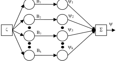
Then, the dual-axissolar tracking controller is composed by two FREN controllers concerning to both the seasonal motion and the daily motion. And these controls are derived based on the fuzzy rules presented above, and its structure can be decomposed into five layers as shown in Fig. 5 and Fig. 6, for the seasonal and daily motions, respectively. As it can be noticed, FREN has a simple structure, which is able to transfer the human knowledge about the solar path during the year and the day (obtained from the astronomical yearbook records), based on fuzzy rules injected into the network. The function of each layer can be described as follows:
Layer 1. This is called the seasonal and daily input layer, for each FREN respectively. In this layer both the input and the input are sent directly to the next layer, therefore, there is no computation on it.
Layer 2. This is called the membership function layer. Each node in this layer has a corresponding membership function produced by gaussian, linear, or sigmoid mathematical functions that correspond to one linguistic level (e.g. negative, positive, etc.); some examples are given in Fig. 10 and Fig. 12. The output value at the i-th and j-th node of each FREN is calculated by and for the input in days and the input in hours, respectively.
Layer 3. This is called the linear consequence layer. In this layer each node is connected directly from the previous node, thus, there are n and k nodes in this layer, for each FREN respectively. The output at the i-th node, in the seasonal FREN, is calculated as
. (3)
And the output at the j-th node, in the daily FREN, is calculated as
, (4)
[image:3.595.326.534.211.318.2]where the parameters and correspond to the i-th node, the parameters and correspond to the j-th node, and the and parameters represent the slope of the linear consequences, corresponding to each FREN controller (Fig. 11 and Fig. 13).
Figure 5. The structure of the seasonal motion FREN controller.
Figure 6. The structure of the daily motion FREN controller.
Layer 4. This is called the output position layer. As it can be notice in Fig. 5 and Fig. 6, the structure of this layer is similar to the output layer of an artificial neural network with weights equal to unity. Thus the output generated by the FREN controller, for the seasonal position, is calculated as
, (5)
where the vector … and the vector … . Finally the output generated by the FREN controller, for the daily position, is calculated as
, (6)
where the vector … and the vector … .
This decomposition into four layers lets the designer to set the initial values of the neural network intuitively. When implementing the proposed dual-axissolar tracking FREN
∑
B1
B2
B3
Bk
∑
A1
A2
A3
An
1
2
3
n
1
2
3
k
[image:3.595.330.530.348.454.2]controller, the control receives both the input and the input corresponding to the days during the year and the hours during the day, respectively. Thereafter, the nominal control signals and , desired positions, are computed by the controller.
III. EXPERIMENTS
A. Experimental Setup and Procedure
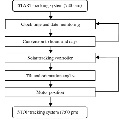
For implementing the controller, an experimental prototype was developed and integrated in our laboratory, based on DYNAMIXEL AX-12 motors by ROBOTIS Inc. Drivers and user interface are programmed in MATLAB. The Dual-Axis Solar Tracking prototype consists on two degrees of freedom to control the tilt and the orientation angle, as shown in Fig. 7. The program reads hour and date from the computer in order to generate suitable inputs to the control algorithm, as shown in Fig. 8. This information is transformed in degrees (or angular position) by means of the intelligent controller and sent to servo-motors for positioning the solar cell. The position of the solar cell is automatically adjusted online when both the clock time and day vary. In Fig. 9, the experimental methodology is summarized as follows:
[image:4.595.306.552.62.323.2]1) The clock time (hour/minutes/seconds) and date (year/month/day) are read from the computer, and converted into hours and days, respectively.
Figure 7. Dual-Axis Solar Tracking prototype.
2) The tilt and orientation positions are computed by the controller for positioning the solar cell perpendicular to the sun.
[image:4.595.338.546.356.562.2]3) The system tracks the sun by adjusting the angular motor position, based on the fuzzy inference system. Although mathematically, there exists a relationship between tilt and orientation angles, day of the year, and clock time; a mathematical model should be defined for each country because this relation varies from country to country. On the other hand, a data base based on the astronomical yearbook could be used for each country, but in practice, this could be an exhaustive task, and a high computational cost is required to execute position control. Besides that in these records, the solar trajectory is described with large intervals between data samples for each set of parameters (, , date, hour), which represents incomplete information about the whole time vector space.
Figure 8. Control system of FREN structure to control seasonal and daily motion, where subscript d denotes desired position.
Figure 9. Flowchart of the experimental methodology.
In contrast, by using our proposed control scheme to maintain the cell normal direction regarding to the sun-light, we provide a formal mathematical description. The fuzzy-based approximation model only needs the range of the tilt angle [min,max] and the range of the orientation angle [min,max] which can be obtained from the astronomical yearbook records for each country. This approach has a low computational cost, that is, in the sense of soft-computing.
By means of the fuzzy inference system, we include the astronomical information based on fuzzy IF-THEN rules. In this regard, we have to define two sets of fuzzy rules. The first set corresponds to the seasonal motion and the second to the daily motion.
The seasonal motion can be defined based on the
following fuzzy rules:
Clock time and date monitoring START tracking system (7:00 am)
Conversion to hours and days
Solar tracking controller
Tilt and orientation angles
Motor position
STOP tracking system (7:00 pm) Controller
Computer Tracking System
d
d
Desired
position
Actual position TABLEI
MATHEMATICAL REPRESENTATION FOR SEASONAL MOTION BASED ON LINGUISTIC LEVEL
Linguistic level Membership Function Linear Consequence
JF, RB 1 exp 0.111 31
MA, RM 12 2053
MJ, RS 1
2 100
24
JA, FS 12 26250
SO, FM 1
2 297
22
ND, FB 1 exp 0.11 320
Motor
Motor Solar-cell
Computer Clock time and date monitoring
Rule 1: IF is JFTHEN is RB, Rule 2: IF is MATHEN is RM, Rule 3: IF is MJTHEN is RS, Rule 4: IF is JATHEN is FS, Rule 5: IF is SOTHEN is FM, Rule 6: IF is NDTHEN is FB,
where JF, MA, MJ, JA, SO, and ND denote January-February, March-April, May-June, July-August, September-October, and November-December linguistic level, respectively. On the other hand, RB, RM, RS, FS, FM, FB
denote Return direction with Big angle, Return direction with Medium angle, Return direction with Small angle,
Forward direction with Small angle, Forward direction with
[image:5.595.47.277.258.384.2]Medium angle, and Forward direction with Big angle, respectively. The membership functions (MFs) are shown in Fig. 10, where all rules are processed.
Figure 10. Setting of membership functions of the dual-axis solar tracking controller, for selected in the input-range [0, 365] days.
After all rules have been processed, the crisp output is computed based on the corresponding linear consequences (LCs) by using defuzzification, as shown in Fig 11. According to the astronomical yearbook records, the initial setting of parameters are given as 48, 30,
15, 15, 30, 48. The mathematical representation of MFs and LCs related with the linguistic levels are shown in Table I.
Figure 11. Setting of linear consequences of the dual-axis solar tracking controller, for selected in the output-range [0, 47.1] degrees, in accordance with astonomical records.
In a similar way, we introduce the daily motion in accordance with the following fuzzy rules:
Rule 1: IF is mTHEN is S, Rule 2: IF is nTHEN is M, Rule 3: IF is aTHEN is L,
where m, n, a, L, M, and S denote morning, noon, afternoon, large, medium, and small, respectively. The membership functions (MFs) are shown in Fig. 12, where all rules are processed. After all rules have been processed, the crisp
output is computed based on the corresponding linear consequences (LCs) by using defuzzification, as shown in Fig 13. According to the astronomical yearbook records, the initial setting of parameters are given as 60,
100, 180. The mathematical representation of MFs and LCs related with the linguistic levels are shown in Table II.
As it can be noticed, the setting of MFs and LCs are selected according to the information coming from the astronomical yearbook records, and the ranges [min,max] and [min,max] can easily be changed depending of the country location. This approach let us to insert knowledge into the controller based on the combination of fuzzy logic and astronomical measurements.
Figure 12. Setting of membership functions of the dual-axis solar tracking controller, for selected in the input-range 7:00 to 19:00 hours.
Figure 13. Setting of linear consequences of the dual-axis solar tracking controller, for selected in the output-range [0, 180] degrees, in accordance with astonomical records.
0 0.1 0.2 0.3 0.4 0.5 0.6 0.7 0.8 0.9 1
0 5 10 15 20 25 30 35 40 45 50
Membership grade
A
ngl
e [
degr
ees]
RB and FB RM and FM
RS and FS
0 50 100 150 200 250 300 350
0 0.2 0.4 0.6 0.8 1
Day of the year
M
e
m
b
er
s
h
ip gr
a
de
JF
MA MJ
JA
SO
ND
0 0.1 0.2 0.3 0.4 0.5 0.6 0.7 0.8 0.9 1
0 50 100 150 200
Membership grade
A
ngl
e [
degr
ees
] L
M
S
6 8 10 12 14 16 18 20 22 24
0 0.2 0.4 0.6 0.8 1
Time [hours]
M
em
b
er
shi
p gr
ade m
n
a
TABLEIII
INFORMATION ACCORDING TO ASTRONOMICAL YEARBOOK RECORDS FROM MEXICO
Parameter Description Range of operation
clock time (input) [7, 19] hours
date (input) [1, 365] days seasonal motion (output) [0, 47.1] degrees daily motion (output) [0, 180] degrees
TABLEII
MATHEMATICAL REPRESENTATION FOR DAILY MOTION BASED ON LINGUISTIC LEVEL
Linguistic level Membership Function Linear Consequence
m, S 12 1.812.5
n, M 1
2 16.2
1.8
[image:5.595.312.545.458.583.2] [image:5.595.73.281.525.636.2] [image:5.595.312.541.618.739.2]B. Experimental Results
In order to illustrate the performance of the proposed intelligent control scheme for positioning the solar cell, real-time experiments were carried out. The control algorithm was implemented on the prototype presented above (Fig. 7). The inputs and outputs of the controller were selected according to the astronomical yearbook records from Mexico [28], summarized on Table III. Based on these four parameters (, , , ), the control automatically computes and adjusts the position with the purpose of achieving perpendicular direction in relation to the panel surface.
To the end of supporting the effectiveness of the proposed controller, experimental results were evaluated and compared with those recorded in the database from the astronomical yearbook. The results of seasonal motion (tilt angle) are depicted in Fig. 14. As it can be notice, good agreement is found between database and experiments. For each day of the year (input), the control is able to compute a suitable output angle-.
The results of daily motion are illustrated in Fig. 15. In this figure is shown the evolution of the output angle- for each corresponding input based on clock time. One can observe that the accuracy of the controller remains during this motion, which is an approximation of a straight line.
This approximation based on fuzzy logic and astronomical information, from a practical point of view, represents a suitable and relevant approach, because the solar tracking system does not required of any electronic devices (as light-sensor, GPS trackers, etc.) for transmitting the relative position of the sun to the controller.
Figure 14. Tilt angle- computed by the proposed controller and compared with the angle obtained from the astronomical records.
Figure 15. Orientation angle- computed by the proposed controller and compared with the angle obtained from the astronomical records.
IV. CONCLUSION
In this paper, a novel dual-axis solar tracking controller has been presented. The core of the control system is based on fuzzy rules constructed by means of the astronomical yearbook records. This scheme automatically adjusts the tilt and orientation angles, taking into consideration the day of the year and clock time. The flexible structure of the control design allows to be used depending on the country location by just modifying the maximum and minimum range of values for and . It is of importance to notice that the control does not require any sensor-device information related with the sun position because its intelligent structure based on the fuzzy engine lets to approximate or infer the sun location. The intelligent algorithm has been implemented in a practical prototype of two degrees of freedom. The experimental results demonstrate the effectiveness and make evident the potential characteristics of our proposal. Finally, we conclude that the proposed controller can easily be implemented for real-world applications, without any solar tracking-sensor, and with low computational cost.
REFERENCES
[1] B. Ai, H. Shen, Q. Ban, B. Ji, X. Liao, “Calculation of the hourly and daily radiation incident on three step tracking planes”, Energy Conversion and Management, Elsevier, Vol. 44, pp. 1999-2011, 2003. [2] P. Roth, A. Georgiev, and H. Boudinov, “Design and construction of a system for sun-tracking”, Renewable Energy, Elsevier, Vol. 29, pp. 393-402, 2004.
[3] F. R. Rubio, M. G. Ortega, F. Gordillo, M. Lopez-Martinez, “Application of new control strategy for sun tracking”, Energy Conversion and Management, Elsevier, Vol. 48, pp. 2174-2184, 2007. [4] M. A. Yakup, and A. Q. Malik, “Optimum tilt angle and orientation
for solar collector in Brunei Darussalam”, Renewable Energy, Elsevier, Vol. 24, 223-234, 2001.
[5] Koray Ulgen, “Optimum Tilt Angle for Solar Collectors”, Energy Sources, Taylor & Francis, Vol. 28, 1171-1180, 2006.
[6] H. Mousazadeh, A. Keyhani, A. Javadi, H. Mobli, K. Abrinia, and A. Sharifi, “A review of principle and sun-tracking methods for maximizing solar systems output”, Renewable and Sustainable Energy Reviews,Vol. 13, 1800-1818, 2009.
[7] S. Bari, “Optimum slope angle and orientation of solar collectors for different periods of possible utilization”, Energy Conversion and Management, Elsevier, Vol. 41, 855-860, 2000.
[8] V. Badescu, “Theoretical derivation of heliostat tracking error distribution”, Solar Energy, Elsevier, Vol. 82, 1192-1197, 2008. [9] A. Bairi, “Method of quick determination of the angle of slope and
the orientation of solar collectors without a sun tracking system” Solar and Wind Technology, Elsevier, Vol. 7, 327-330, 1990. [10] M. Blanco-Muriel, D. C. Alarcón-Padilla, T. López-Moratalla, M.
Lara-Coira, “Computing the solar vector”, Solar Energy, Elsevier, Vol. 70, 431-441, 2001.
[11] F. R. Rubio, M. G. Ortega, F. Gordillo, and M. López-Martínez “Application of new control strategy for sun tracking”, Energy Conversion and Management, Elsevier, Vol. 48, 2174–2184, 2007. [12] P. Roth, A. Georgiev, and H. Boudinov, “Cheap Two Axis sun
following device”, Energy Conversion and Management, Elsevier, Vol. 46, 1179–1192, 2005.
[13] P. Roth, A. Georgiev, and H. Boudinov, “Design and construction of a system for sun-tracking”, Renewable Energy, Elsevier, Vol. 29, 393-402, 2004.
[14] R. Doraiswami, S. Price, “A Robust Position Estimation Scheme Using Sun Sensor”, IEEE Transactions on Instrumentation and Measurement, Volume 47, 595-603, 1998.
[15] M. Alata, M.A. Al-Nimr, and Y. Qaroush, “Developing a multipurpose sun tracking system using fuzzy control”, Energy Conversion and Management, Elsevier, Vol. 46, 1229-1245, 2005. [16] I.H. Altas, and A.M. Sharaf, “A novel maximum power fuzzy logic
controller for photovoltaic solar energy systems”, Renewable Energy, Elsevier, Vol. 33, 388-399, 2008.
0 50 100 150 200 250 300 350
0 10 20 30 40 50
Day of the year
T
il
t angl
e [
de
grees
]
Controller
Astronomical Yearbook
8 10 12 14 16 18 20
0 50 100 150 200
Time [hours]
Or
ie
n
tat
io
n
an
gl
e
[
d
eg
re
e
s
]
Linear reference
[image:6.595.48.286.423.562.2] [image:6.595.43.283.596.739.2][17] C. B. Salah, M. Chaabene, and M. B. Ammar, “Multi-criteria fuzzy algorithm for energy management of a domestic photovoltaic panel”, Renewable Energy, Elsevier, Vol. 33, 993-1001, 2008.
[18] M. Paulescu, P. Gravila, and E. Tulcan-Paulescu “Fuzzy logic algorithms for atmospheric transmittances of use in solar energy estimation”, Energy Conversion and Management, Elsevier, Vol. 49, 3691-3697, 2008.
[19] A. Mellit, and A. M. Pavan, “A 24-h forecast of solar irradiance using artificial neural network: Application for performance prediction of a grid-connected PV plant at Trieste, Italy”, Solar Energy, Elsevier, Vol. 84, 807-821, 2010.
[20] A. Moghaddamnia, R. Remesan, M. H. Kashani, M. Mohammadi, D. Han, and J. Piri, “Comparison of LLR, MLP, Elman, NNARX and ANFIS Models with a case study in solar radiation estimation”, Journal of Atmospheric and Solar-Terrestrial Physics, Elsevier, Vol. 71, 975–982, 2009.
[21] H. Yang, W. Zhou, L. Lu, and Z. Fang, “Optimal sizing method for stand-alone hybrid solar-wind system with LPSP technology by using genetic algorithm”, Solar Energy, Elsevier, Vol. 82, 354-367, 2008. [22] F. M. Al-Naima, and N. A. Yaghobian, “Design and construction of a
solar tracking system”, Solar and Wind Tech., Elsevier, Vol. 7, 611-617, 1989.
[23] J.S. Jang, “ANFIS: adaptive-network-based fuzzy inference system”, IEEE Transactions on Systems, Man, and Cybernetics, Vol. 23, 665-685, 1993.
[24] C. H. Lee, C. C. Teng: “Identification and control of dynamic systems using recurrent fuzzy neural networks”, IEEE Transactions on Fuzzy Systems, Vol. 8, 349-366, 2000.
[25] C. Treesatayapun, “Fuzzy rules emulated network and its application on nonlinear control systems”, Applied Soft Computing, Elsevier, Vol. 8, 996-1004, 2008.
[26] J. Armendariz, C. Treesatayapun, A. Baltazar, “Force feedback controller based on fuzzy-rules emulated networks and hertzian contact with ultrasound”, Mechanical Systems and Signal Processing, Elsevier, vol. 27, pp. 534-550, 2011.
[27] J. A. Duffie, W. A. Beckman, “Solar Engineering of Thermal Processes”, Wiley, 3rd edition, 2006.
[28] Astronomical yearbook records from Mexico, Institute of Astronomy, UNAM, Mexico ( http://www.astroscu.unam.mx/anuario/ ). [29] T. Shin Yeow, “The Analemma for Latitudinally-Challenged People”,
![Figure 1. Equatorial coordinate system (right ascension and declination [29]).](https://thumb-us.123doks.com/thumbv2/123dok_us/475295.545850/2.595.305.541.348.682/figure-equatorial-coordinate-right-ascension-declination.webp)