Abstract—In Japan, regional activation is one of the most important problems for regional areas such as Fukui prefecture. Therefore, several kinds of activities are performed for local res-idents. Moreover, some approaches with ICT are performed for sightseeing because the rank of sightseeing in Fukui prefecture is somewhat lower than other prefecture in Japan. It is expected that the sightseeing advances and the region is activated with these approaches. In this paper, we propose a video streaming system for the sightseeing in order to advance the regional activation. In this system, a virtual network for each tourist spot is constructed over a physical network by using the network virtualization technology, and the real-time video of the tourist spot is delivered to other spots over the virtual network. The local residents and the tourists become interested in the tourist spot by watching the video. Here, virtual networks are designed with two optimization problems so that resources are used in each link evenly and the total amount of resources that are used in the virtual networks is minimized. Note that each virtual network is designed as a star topology with the optimization problems. We evaluate the performance of our proposed method with simulation, and numerical examples show the effectiveness of the proposed method.
Index Terms—Virtual networks, Topology design, Optimiza-tion problem, Video streaming, Regional activaOptimiza-tion
I. INTRODUCTION
I
N Japan, regional activation is one of the most important problems for regional areas such as Fukui prefecture. Several kinds of activities are performed for the regional activation. Table I shows the data in terms of the sightseeing for each prefecture in Japan. From these data, the rank of Fukui prefecture is somewhat lower than other prefectures. Therefore, in Fukui prefecture, several efforts such as the infrastructure construction are performed. In addition, some approaches with ICT have been performed [1], [2]. For example, [2] utilizes virtual networking technologies [3], [4], [5] and delay tolerant network technologies [6], [7], [8] to increase the number of tourists in Fukui prefecture for the regional activation. Such activities are expected to be effective for many regional areas around the world not only for Fukui prefecture.To increase the number of tourists in regional areas, it is indispensable to provide the sightseeing information in real time with users. On the other hand, the real-time video streaming requires a high bandwidth in the Internet. This degrades the quality of other services, and hence it is not expected that such a video streaming system is utilized worldwide.
Y. Urayama is with Graduate School of Engineering, University of Fukui, Fukui 910–8507, Japan. Email: [email protected]
T. Tachibana is with Graduate School of Engineering, University of Fukui, Fukui 910–8507, Japan. Email: [email protected]
TABLE I
DATA OF47PREFECTURES INJAPAN[9].
Number of
visitors Travel cost
Degree of satisfaction
Future visit intension 1. Tokyo
14,990,000 1. Okinawa93,400 yen 1. Okinawa91.0% 1. Hokkaido33.8% 2. Hokkaido
9,780,000 2. Hokkaido66,800 yen
2. Kyoto
90.9% 2. Okinawa31.7% 3. Kanagawa 8,370,000 3. Tokyo 62,900 yen 3. Miyagi 88.1% 3. Kyoto 17.3% .. . ..
. 18. Fukui84.4% ... ..
. 42. Fukui
1,370,000 ... ... 42. Fukui1.5% ..
. 33,600 yen43. Fukui ... ..
.
In this paper, we propose a video streaming system that utilizes virtual network technologies. In this system, to provide the real-time promotional video of each tourist spot with users, a virtual network where all spots are included is constructed for each tourist spot. Here, the bandwidth of a link between two tourist spots is higher than that of other links. This keeps the quality of the streaming video at other tourist spots. Moreover, a topology of each virtual network is designed by solving two optimization problems. The derived topology can avoid the intensive utilization of network resources at each link and can reduce the total amount of resources that are used to construct virtual net-works. We evaluate the performance of our proposed system with simulation.
The rest of this paper is organized as follows. Section II explains related work and Sect. III describes the overview of our proposed system. Section IV describes a virtual net-work construction method for our proposed system. Section V shows some numerical examples, and Sect. VI denotes conclusions.
II. RELATED WORK
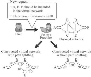
Fig. 1. Path splitting.
constructing the virtual network to a service provider. The request has the information about nodes that should be included in the virtual network and the amount of network resources that are used in the virtual network. The service provider designs a topology of the virtual network ac-cording to the user’s request by performing the path splitting and the path migration. Here, these processes are formulated as optimization problems for the network resource allocation. In the path splitting, the service provider can design a new virtual network where there are one or more links between any two requested nodes (see Fig. 1). On the other hand, the path splitting may trigger a packet reordering in each virtual network because multiple routes can be used at the same time between a source node and a destination node [11]. Therefore, users select whether the path splitting is used or not by setting the value of as follows:
Now, virtual networks have been constructed over the physical network. Let the total amount of resources for link
between node and node be denoted as and
the total amount of resources of node be denoted as . Moreover, and are the amount of resources that have
been used for and in the th virtual
network, respectively. In the new virtual network, denotes the amount of resources that are used in , and
denotes the amount of resources that are used in . When a user sends a request for constructing a new virtual network to a service provider, a new topology of the virtual network is designed by solving the following optimization problem.
subject to
Fig. 2. Path migration.
In this optimization problem, the topology of the new virtual network is designed by deriving and . In (1), the topology of the new virtual network can be designed so that the robustness of the physical network is maximized, that is, network criticality can be minimized [12]. Here, in this optimization problem, and are selected among the requested nodes before solving the opti-mization problem. Note that and are selected among the requested nodes and the above optimization problem is performed until the topology design is completed.
[image:2.595.70.265.54.219.2] [image:2.595.313.529.56.514.2]problem for the path migration is formulated as follows:
subject to
Amount of resources of node that have been used for in new virtual network.
Amount of resources of link that have been used for in virtual network .
Amount of resources of node that have been used for in virtual network .
Number of tourist spots. Set of tourist spots. Set of other general spots.
Amount of resources of virtual link that have been used between spot and spot in virtual network .
Amount of resources of link that have been used for in virtual network .
Total amount of resources of link that have been used between spot and spot in virtual network .
Amount of resources of link that are connected to tourist spot in a virtual network.
Amount of resources of link that are connected to other general spot in a virtual network.
Solution offirst optimization problem.
As is the case with the path splitting, and are determined in advance. In this optimization problem, for the constructed virtual networks, topologies of virtual networks are redesigned so as to satisfy construction conditions from (31) to (37). Moreover, topologies of virtual networks are redesigned so as to satisfy construction conditions from (38) to (45).
When is equal to zero in the new request, the path splitting can not be performed for the new virtual network. Therefore, the above optimization problem (16) to (45) has to be modified. First, construction conditions (22) to (25) is omitted from the above optimization problem, and the following construction conditions are added.
III. PROPOSED VIDEO STREAMING SYSTEM
Fig. 3. Overview of our proposed system.
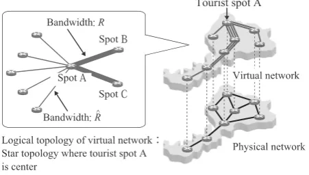
Figure 3 shows an overview and the effective of our proposed system. As shown in Fig. 3, in our proposed system, the real-time promotional video of each tourist spot is delivered to other spots. Local residents and tourists can get the information about each tourist spot in real time, and it is expected that the local residents and the tourists take an interest in the tourist spots by watching the videos. In order to realize our proposed system, a virtual network for each tourist spot is constructed over a physical network. In each virtual network, a promotional video for a tourist spot is delivered to other spots.
Figure 4 shows an example where promotional videos for two tourist spots are delivered to tourists and local residents by using our proposed system. In this figure, a virtual network for the tourist spot and a virtual network for the tourist spot are constructed over a physical network. The promotional video of spot and that of spot are delivered over the corresponding virtual network, respectively. Because these virtual networks are constructed independently, each promotional video is delivered independently of other pro-motional videos.
If a tourist watches a promotional video for a tourist spot at another spot and the tourist becomes interested with the tourist spot, he might move to the spot for the sightseeing. Moreover, if local residents watch promotional videos, they may visit the spots frequently. Therefore, it is expected that the number of tourists for each spot increases and the region is activated by utilizing our proposed system.
IV. TOPOLOGY DESIGN OF VIRTUAL NETWORKS
In our proposed system, multiple virtual networks for tourist spots are constructed over a physical network where some existing services have been provided. Therefore, when our proposed system is utilized, it is important to consider the impact of the construction of virtual networks on the quality of the existing services. In particular, it is expected that this system is operated with less network resources because this
Fig. 4. Virtual networks for two tourist spots.
system is only used for the sightseeing whose priority is not high. In this paper, the topology of virtual networks is limited to the star topology. Moreover, we design these topologies by solving two optimization problems about network resources.
A. Avoidance of intensive utilization of network resources Now, let denote the number of all spots in a physical network as and the number of tourist spots as . In the physical network, virtual networks are constructed for the tourist spots. Here, the set of the tourist spots is denoted as , and the set of other general spots that are not included in is denoted as . When we denote an adjacency matrix
for a tourist spot as , an element for the
th row and the th column of is given by
(54)
In (54), and denote the amount of resources that are allocated to each link in each virtual network, and these are set so as to satisfy . This means that more network resources (bandwidth) are allocated to a link between two tourist spots nodes in order to deliver the promotional video with high quality (see Fig. 5).
In terms of the virtual network for the tourist spot , we denote an adjacency matrix for the physical network as . Moreover, the amount of resources that is used in link between nodes and in the physical network is denoted as
. Because each virtual network satisfies (54), is given by
(55)
From (55), the element for the th row and the th column of is given by
(56)
[image:4.595.62.277.54.298.2] [image:4.595.338.510.54.203.2]Fig. 5. Topology design of virtual networks for the sightseeing.
the following optimization problem.
(57)
subject to (58)
(59) (60) In (57), the maximum amount of resources that are used at links in the physical network is minimized in order to avoid the intensive utilization of network resources. Moreover, (58) shows the total amount of resources that can be used at each link in the virtual networks. (59) and (60) show the amount of resources that are used at each link in the virtual networks. By solving the above optimization problem, we can construct the virtual networks while avoiding the intensive utilization of network resources in the physical network.
B. Reduction of total amount of resources for virtual net-works
After the optimization problem in the subsection IV-A is solved, another optimization problem is solved and the optimal topologies of the virtual networks can be obtained. By solving the second optimization problem, the total amount of network resources that are needed to construct the virtual networks can be reduced. When the solution of the first optimization problem is , the second optimization problem is formulated as follows:
(61)
subject to (62)
(63) (64) (65) In (61), the total amount of resources that is used in virtual networks can be minimized. Moreover, in (62), the intensive utilization of network resources can be avoided because the solution of the first optimization problem is kept. In (63), the maximum amount of resources that are used at links in the physical network is minimized as is the case with (58). (64) and (65) show the amount of resources that are used at each link in the virtual networks as is the case with (59) and (60). By solving this optimization problem, we can obtain the topologies so that the total amount of resources for virtual networks are reduced.
Fig. 6. Physical network for simulation.
V. NUMERICALEXAMPLES
In this section, we evaluate with simulation the effective-ness of our proposed system for a physical network shown in Fig. 6. In this physical network, the number of nodes is 12 and the number of links is 18. Moreover, for tourist spots, virtual networks are constructed over the physical network by using our proposed topology design explained in Sect. IV. In each virtual network, the amount of resources that is allocated to a link between two tourist spots is set to 15, and the amount of resources that is allocated to other links is set to 2. For the performance comparison, we evaluate the performance of another virtual network construction method that is calledMinimized hopsin the following. In the minimized hops method, star topologies are designed so as to minimize the total number of hops from a tourist spot whose promotional video is delivered to other spots.
[image:5.595.56.282.57.185.2]Figure 7 shows the maximum amount of resources that are used in links when is equal to 2. Here, the set of tourist spots includes two nodes that are selected from , , , and in Fig. 6. From Fig. 7, we canfind that our proposed system can reduce the maximum amount of resources used in links more significantly than the minimized hops method regardless of a pair of tourist spots. Therefore, the intensive utilization of network resources can be avoided by using our proposed system.
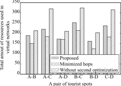
Figure 8 shows the total amount of resources that are needed to construct virtual networks when is equal to 2. From thisfigure, we canfind that our proposed system uses more network resources than the minimized hops method. In the minimized hops method, each spot is connected along the shortest path. As a result, the total amount of resources that are needed to construct the virtual networks is small. However, in the proposed system, the total amount of resources can be reduced by solving the second optimization problem that described in subsection IV-B. As a result, the effectiveness of our proposed method is not lower than the minimized hops method so much.
[image:5.595.50.293.237.315.2] [image:5.595.53.293.569.648.2]Fig. 7. Maximum amount of resources used in links ( =2) .
Fig. 8. Total amount of resources that are needed to construct virtual networks ( =2) .
VI. CONCLUSIONS
In this paper, for the regional activation, we proposed a video streaming system of the sightseeing information by using network virtualization technologies. In this system, a virtual network is constructed for each tourist spot, and the promotional video for each tourist spot is delivered to other spots over each virtual network. Topologies of these virtual networks are designed by solving two optimization problems. We evaluated the effectiveness of our proposed system with computer simulation. From numerical examples, we found that the intensive utilization of network resources for the physical network can be avoided by using our proposed system. Moreover, we found that the total amount of resources that are needed to construct virtual networks is reduced by performing the optimization problems.
ACKNOWLEDGEMENT
This work was partly supported by the Strategic Informa-tion and CommunicaInforma-tions R&D PromoInforma-tion Programme of the Ministry of Internal Affairs and Communications, JAPAN.
REFERENCES
[1] S. Murata and T. Tachibana, “Information Distribution System with Dis-tributed Reinforcement Learning for Providing Local Information,”The International Multi Conference of Engineers and Computer Scientists 2014 (IMECS 2014), Mar. 2014.
[2] T. Tachibana, T. Hori, S. Fukuma, M. Fujimoto, and N. Handa, “A Study on Software Defined Networking and Delay Tolerant Networking Technologies for Regional Security and Activation,” NS2013–105, Aug. 2013.
[image:6.595.69.273.56.200.2]Fig. 9. Maximum amount of resources used in links ( =3) .
Fig. 10. Total amount of resources that are needed to construct virtual networks ( =3) .
[3] A. Berl, A. Fischer, and H. Meer, “Using System Virtualization to Cre-ate Virtualized Networks,”Electronic Communications of the EASST, vol. 17, pp. 1–12, Mar. 2009.
[4] H. Aun, P. Richard, and N. Akihiro, “Challenges in Resource Allocation in Network Virtualization,” inProc. 20th ITC Specialist Seminar on Network Virtualization, May 2009.
[5] A. Nakao, “Network Virtualization as Foundation for Enabling New Network Architectures and Applications”IEICE Transactions on Com-munications, vol. E93.B, no. 3, pp. 454–457, Mar. 2010.
[6] V. Cerf, S. Burleigh, A. Hooke, L. Torgerson, R. Durst, K. Scott, E. Travis, and H. Weiss, “Delay-tolerant Network Architecture,”IETF RFC4348, Apr. 2007.
[7] J. Shen, S. Moh, and I. Chung, “Routing Protocols in Delay Tolerant Networks: A Comparative Survey,” in Proc. The 23rd International Technical Conference on Circuits/Systems, Computers and Communi-cations (ITC-CSCC 2008), July 2008.
[8] E. Bulut and B.K. Szymanski, “Friendship Based Routing in Delay Tolerant Mobile Social Networks,” in Proc. IEEE Globecom 2010, pp. 1–5, Dec. 2010.
[9] http://www.j-smeca.jp/attach/kenku/shibu/h23/y fukui.pdf.
[10] Y. Urayama and T. Tachibana, “Virtual Network Construction with K-Shortest Path Algorithm and Optimization Problems for Robust Phys-ical Networks,” submitted toInternational Journal of Communication Systems.
[11] M. Yu, Y. Yi, J. Rexford, and M. Chiang, “Rethinking Virtual Network Embedding: Substrate Support for Path Splitting and Migration,”ACM SIGCOMM Computer Communication Reviewvol. 38, no. 2, pp. 17–29, Apr. 2008.
[12] A. Tizghadam and A. Leon-Garcia, “Autonomic Traffic Engineering for Network Robustness,”IEEE Journal on Selected Areas in Commu-nicationvol. 28, no. 1, pp. 39–50, Jan. 2010.
[image:6.595.68.272.235.381.2] [image:6.595.323.529.236.382.2]