222 IEEE JOURNAL OF QUANTUM ELECTRONICS, VOL. 38, NO. 2, FEBRUARY 2002
Modeling of High-Power Continuous-Wave Tm:YAG
Side-Pumped Double-Clad Waveguide Lasers
Jacob I. Mackenzie, Student Member, IEEE, Cheng Li, David P. Shepherd, Member, IEEE, Raymond J. Beach, and
Scott C. Mitchell
Abstract—A plane-wave model accounting for cross-relaxation, upconversion, ground-state depletion, and gain saturation in continuous-wave laser systems is applied to side-pumped Tm:YAG double-clad planar waveguides. The temperature profile due to high-power pumping, and the delivery and absorption efficiencies of proximity-coupled diode bars, are also calculated. The theo-retical performance is found to be a good fit to the experimental results, which show 15-W output at 2 m from 43 W of diode pump power. The output channels for the absorbed power are quantified, and it is shown that upconversion limits the gain and, hence, the size of the output coupling that can be used in such lasers. The same theory is then used to design a very compact waveguide laser capable of delivering 100 W of output power.
Index Terms—Laser thermal factors, lasers, upconversion, waveguides.
I. INTRODUCTION
H
IGH-power lasers at 2 m are of interest for several appli-cations due to the strong absorption by water and human tissue, the low atmospheric absorption, and the eye-safe prop-erties of light in this wavelength region. Operation of Tm:YAG on the transition is an attractive system for such lasers as it allows pumping by AlGaAs diodes around 0.8 m, while maintaining high efficiency and low thermal loading. This is possible, despite the large difference between the pump and laser photon energies, because of a favorable cross-relaxation process that leads to a pumping quantum efficiency approaching 2. The disadvantages of the system include its quasi-three-level nature, the presence of energy-transfer upconver-sion, and a relatively low emission cross-section.End- and side-pumped bulk Tm:YAG lasers have been reported at continuous-wave (CW) powers of using lens ducts [1] and parabolic concentrators [2] to achieve the required intense pumping density. Waveguide geometries have also been used for 2- m laser systems, both in planar [3] and fiber [4] format. Recently, we have reported a double-clad Tm:YAG planar waveguide that delivers 15 W of output at 2 m when side-pumped by two 20-W diode bars [5]. The double-clad waveguide has the advantage of allowing prox-imity-coupling of the diode bars, leading to a very simple and compact device. Here, we model the performance of
Manuscript received August 23, 2001; revised November 5, 2001. This work was supported in part by a U.K. EPSRC Grant GR/M98449/01 and by Eglin Air Force Base under Contract F08630–99-C-0016.
J. I. Mackenzie, C. Li, and D. P. Shepherd are with the Optoelectronics Re-search Centre, University of Southampton, Southampton SO17 1BJ, U.K.
R. J. Beach and S. C. Mitchell are with the Maxios Laser Corporation, Liv-ermore, CA 94550 USA
Publisher Item Identifier S 0018-9197(02)00624-3.
this laser, including the delivery and absorption of the pump power and the expected thermal load, in order to investigate its potential for power scaling. The laser model is a modified version of that presented by Beach [6], which accounts for ground-state depletion, gain saturation, cross-relaxation, and upconversion. The model also allows easy identification of the channels into which the absorbed pump power is routed, clearly demonstrating the regime in which upconversion can come to dominate the laser performance.
This paper is organized as follows. Section II models the pump-power delivery achieved through the proximity-coupling technique, giving the waveguide numerical aperture ( ) and coupling distance requirements for efficient pump launch. Beam propagation method (BPM) calculations, which calculate the 3-D propagation of the field through the waveguide in small in-crements, are then used to model the absorption efficiency of the double-clad planar structure in comparison to that of uniformly doped material, demonstrating that taking the ratio of the doped to undoped areas is a good approximation for the reduction in absorption coefficient. In Section III, the CW theory of end-pumped quasi-three-level lasers presented by Beach [6] is mod-ified to account for side-pumping, the double-clad waveguide geometry, and the presence of upconversion and cross-relax-ation, to model the output power characteristics of the Tm:YAG waveguide laser. A close fit is obtained using values for the propagation loss and upconversion coefficient in good agree-ment with those reported in the literature. We then identify the amount of power going into the output, upconversion, fluores-cence, thermal and loss channels. Optimization of the present system is also discussed. In Section IV, the thermal properties of the slab-like waveguide are discussed and fed back into the laser model of Section III, allowing a design to be made for a compact 100-W waveguide laser that is well within any limits imposed by the thermal loading. Finally, in Section V, we give our concluding remarks.
II. PUMP-POWERDELIVERY ANDABSORPTIONEFFICIENCY
A. Pump-Power Delivery
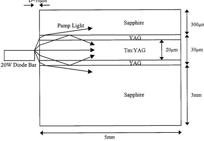
The geometrical match between the emission aperture of a diode bar and the planar waveguides used in these experiments allows the use of proximity coupling, leading to very simple and highly compact laser systems. The waveguide design and the proximity coupling of a single diode bar to the double-clad structure are shown schematically in Fig. 1. In the experiments described here, the Tm:YAG double-clad waveguide was pumped from both sides by two diode bars from Coherent Inc.
MACKENZIE et al.: MODELLING OF HIGH-POWER CW TM:YAG SIDE-PUMPED DOUBLE-CLAD WAVEGUIDE LASERS 223
Fig. 1. Schematic diagram of proximity-coupling a diode bar to a double-clad Tm:YAG waveguide.
with a specified full-width half-maximum (FWHM) divergence of 35 in the fast axis. Assuming a diffraction-limited Gaussian output beam from the diode in this axis and an anti-re-flection (AR)-coated input face, we can make an estimate of the delivery efficiency into the central YAG layers using
[image:2.612.305.546.351.569.2](1) where is the angle of propagation (in degrees) of the diver-gent diode beam with respect to the axis of the planar wave-guide. If the half-angle subtended by the YAG central layers to the diode emission aperture is smaller than the angular acceptance of the waveguide , then (1) describes the overlap of the diverging pump beam with the physical aperture of the YAG central layers. Any light incident on the waveguide outside this aperture is lost. If the angular acceptance of the waveguide is less than , then (1) describes the fraction of the diverging pump beam that is contained by the numerical aper-ture of the YAG/sapphire waveguide. In our experimental setup ( ), it is the latter condition that applies. Equation(1) will slightly underestimate the delivery efficiency due to the fact that pump light propagating at angles larger than the waveguide is not totally lost, as partial reflection will still occur at each bounce from the YAG/sapphire interface. A small contribution would also be made to the absorbed power by light reflecting from the upper sapphire/air interface. Fig. 2 shows how the delivery efficiency varies with diode coupling distance and the waveguide . It can be seen that the de-livery efficiency saturates as the is increased for a given coupling distance, and as the coupling distance is reduced for a given . It also shows that for the particular values of diode
Fig. 2. Delivery efficiency against coupling distance and waveguide numerical aperture.
beam divergence and waveguide dimensions used here, the cou-pling efficiency approaches 100% when the coucou-pling distance is m and the numerical apertures is . A delivery ef-ficiency of 0.942 is calculated for our combination of coupling distance (10 m) and (0.47).
224 IEEE JOURNAL OF QUANTUM ELECTRONICS, VOL. 38, NO. 2, FEBRUARY 2002
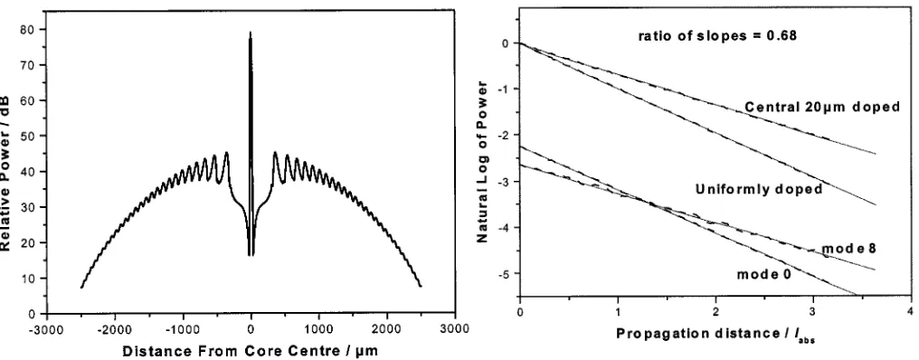
Fig. 3. Calculated pump power distribution at the end of the waveguide assuming no absorption (NB logarithmic scale).
diode, reflections from the AR coating, and (as previously dis-cussed) reflection of power beyond the of the waveguide. Nevertheless, it is clear that this is a very compact and efficient method of pump delivery.
B. Absorption Efficiency
A simple assumption can be made that the absorption coef-ficient of the pump radiation delivered to the waveguide will be reduced by a factor , equal to the ratio of the doped to undoped area of the YAG layers, compared to uniformly doped material. However, this assumption does not account for the dif-ferent overlap of the various propagation modes allowed by the waveguide with the central doped region. With this in mind, we used a commercial BPM package1 to compare the absorption
efficiency of the structure shown in Fig. 1 to a similar structure with uniform doping throughout the YAG layers. The results, shown in Fig. 4, show that the absorption coefficient is reduced by , whereas the simple assumption above leads to a value of 0.67. The very small difference in these figures is due to the larger absorption coefficients of lower order modes, which approach that of uniformly doped material, compared to those of higher order modes. This modeling is based on a per-fectly aligned diode, which leads solely to the excitation of even modes within the YAG layers. However, the same modeling for a diode offset vertically by 5 m, so that the odd modes are also excited, gives nearly identical results.
III. LASERPERFORMANCE
A. Output Power
The laser performance of the 1-cm-long double-clad Tm:YAG waveguide shown in Fig. 1, when pumped from both sides with two 20-W diode bars, was compared to predictions based on a quasi-three-level laser model [6]. This plane-wave model, modified to account for cross-relaxation and upconver-sion in the system and the side-pumped geometry, is
1Kymata Software
Fig. 4. Absorption of pump radiation against distance in units of absorption length (l ). Dashed lines: calculated power. Solid lines: linear fits. The upper two curves show the absorption in uniformly doped and centrally doped waveguides. The lower two curves show the absorption of the lowest order mode and a higher order mode in the centrally doped waveguide.
likely to be a good approximation due to the relatively uniform nature of the gain distribution and laser saturation. In the guided plane this is due to the double-clad waveguide structure. For the 10 at.%-doped, 5-mm-wide, double-clad waveguide and the output coupler used in our experiments, the single-pass pump absorption (see Appendix) is calculated to be 0.73 (compared to a nonsaturated absorption of 0.756), in good agreement with experimental observation. Thus, the double-sided pumping will also give a relatively uniform gain profile in the nonguided plane (we calculate a 24% variation in the upper-laser-level population density across the width of the guide for the case of unsaturated pump absorption). The laser saturation of the gain in the nonguided direction will also be relatively plane wave in nature, due to the highly multimode output in this axis. The model also allows easy identification of the various channels into which the absorbed pump power is routed. The details of the modified model are given in the appendix while here we present the main results and the parameters used.
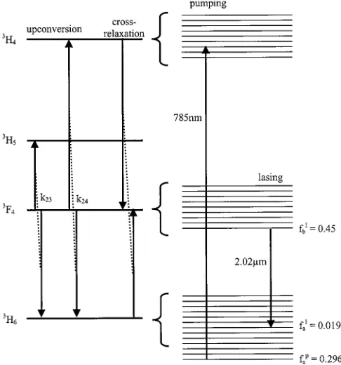
The Tm:YAG energy levels and the pumping, cross-relax-ation, upconversion and lasing processes are shown in Fig. 5. The output power of the laser is related to the incident pump power by
(2)
where the slope efficiency with respect to incident power is
(3)
and the threshold incident power is
MACKENZIE et al.: MODELLING OF HIGH-POWER CW TM:YAG SIDE-PUMPED DOUBLE-CLAD WAVEGUIDE LASERS 225
Fig. 5. Schematic diagram of the Tm:YAG energy levels involved in the 2-m laser operation. The upconversion and cross-relaxation processes considered in the model are indicated on the left and the Boltzmann occupation factors of the relevant Stark levels at 306 K are shown on the right.
In (3) and (4), is the population density of the excited state manifold given by
(5)
and and are the integrated inversion densities (with re-spect to width and length , respectively), and are referenced to the Stark levels coupled by the pump and laser radiation as
(6)
(7)
Here, is the lasing dopant density, is the terminal laser Stark level Boltzmann occupation factor, is the initial laser Stark level Boltzmann occupation factor, and is the initial pump Stark level Boltzmann occupation factor.
Table I gives a list of the parameters used in (3) – (7). The quantum yield, which accounts for the cross relaxation process shown in Fig. 5 is set at 1.98 using the data presented by Honea et al. [1] and accounting for our doping level of 10 at.%. The mode-fill efficiency is set at 1 as the laser mode is expected to efficiently sweep out the available gain due to the double-clad structure and its multimode nature in the nonguided axis. The emission and absorption cross-sections are set relative to the Boltzmann occupation factors [1], [6]. The overlap of the pump with the doped area was discussed in Section II and the overlap of the laser with the doped area is calculated assuming that the laser operates on the fundamental guided mode (as found exper-imentally). The Boltzmann factors are calculated using the Stark splittings reported by Gruber [7], and assuming an average op-erating temperature of 306 K (see Section III).
TABLE I LASERMODELPARAMETERS
The values for the effective lifetime and waveguide transmis-sion are found by fitting to the experimental laser performance as shown in Fig. 6. The effective lifetime of 2.1 ms is related to the low-excitation lifetime ms, and the upcon-version rate coefficient , by
(8)
226 IEEE JOURNAL OF QUANTUM ELECTRONICS, VOL. 38, NO. 2, FEBRUARY 2002
Fig. 6. Output power against pump power.
waveguides [10],[11] (0.2 dB/cm) and is approaching reported values at 1 m for bulk Nd:YAG rods [12] (0.03 dB/cm). The excellent fit to the experimental results using reasonable param-eter values allows predictions to be made for optimization and power scaling of this system with some confidence.
B. Output Channels for Input Power
The model allows for easy identification of the routing of the input pump power into the various possible output channels. Here, the output channels are identified as the output power, given by (2), the fluorescence power
(9)
the upconversion power
(10)
the quantum-defect thermal power
(11)
and the power loss
(12)
[image:5.612.303.547.68.253.2]Fig. 7 shows a plot of these various output channel powers against output coupling for the maximum experimental input power of 43.8 W. It should be noted that the corresponding ab-sorbed power varies with the output coupling, but is approxi-mately equal to 30 W across the range shown in Fig. 7. The graph shows that the use of a output coupler is near optimum for this pump power level and that the power going to heat at this point is nearly 7 W. It should be noted that a cer-tain fraction of the upconversion power will also be converted to heat due to nonradiative decay of the ions promoted into the level. However, at optimum output coupling, this contribution to the total heating power is small compared to the quantum-de-fect thermal power given in (11), and has been neglected in our thermal calculations (Section IV). It can also be seen that the
Fig. 7. Output channels for the input power against output coupler reflectivity for the maximum pump power of 43.8 W.
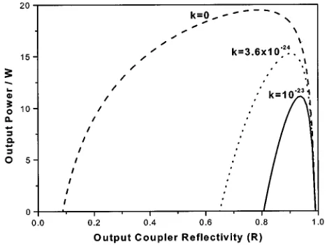
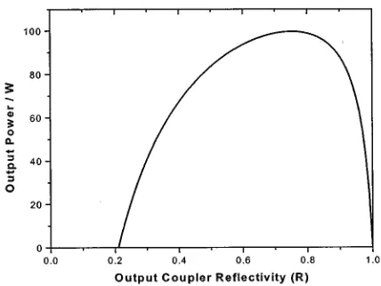
Fig. 8. Output power against output coupler reflectivity for various values of upconversion rate coefficientk (in m s ).
range of output coupling, and hence the achievable gain, is lim-ited due to upconversion becoming the dominant output channel for the absorbed pump power. This is confirmed by Fig. 8, where the theoretical output power is plotted against output coupling for various values of the upconversion rate coefficient. Our ex-perimental observation that we were unable to obtain lasing with a 50% output coupler is, therefore, attributed to the presence of upconversion. Similar effects due to energy-transfer upcon-version have also recently been described in CW -doped lasers [13]. The main reason for the drop in output power at low reflectivity for the case where no upconversion is present is depletion of the ground state, leading to a smaller absorption efficiency.
C. Optimization of Doping Level
[image:5.612.309.543.305.481.2] [image:5.612.37.291.421.585.2]MACKENZIE et al.: MODELLING OF HIGH-POWER CW TM:YAG SIDE-PUMPED DOUBLE-CLAD WAVEGUIDE LASERS 227
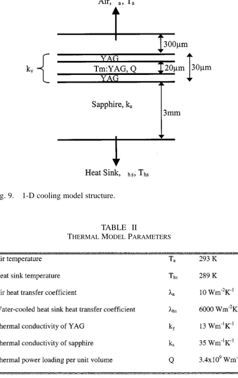
Fig. 9. 1-D cooling model structure.
TABLE II
THERMALMODELPARAMETERS
relatively uniform gain distribution. Reducing the width would also help to decrease the Fresnel number of the cavity and, hence, improve the of the output in the nonguided plane. However, this would bring with it a penalty in terms of increased upconversion coefficients [9] and a greater thermal load per unit volume. Consequently, a drop in output power of nearly 1 W is expected by going to the 15 at.% doping level. If we reduce the doping level from 10 at.%, we are forced to increase the width of the guide to maintain the same pump absorption efficiency, which in turn would adversely effect the output value. An initially very slight reduction in the quantum yield would also but we would nevertheless expect an increase in output power, due to reduced upconversion and thermal load, of 0.5 W by going to a 5 at.% doping level.
IV. THERMALPROPERTIES ANDPOWERSCALING
Planar waveguide lasers have been shown to exhibit simi-larly good thermal management properties to bulk slab lasers [14],[15]. Here, we model the temperature rise in our particular structure and its implications for power scaling to the 100-W level. A simple 1-D model [14], [15] based on the architecture shown in Fig. 9 and using the parameters listed in Table II gives the temperature distribution near the core shown in Fig. 10.
Fig. 10. Temperature distribution near the waveguide core.
The value of used in this model is based on a thermal power of 3.4 W. This is chosen to calculate the temperature used in the laser model (306 K) as an average figure between zero and full pumping power when 6.8 W of thermal power is predicted. The temperature in the core is predicted to be 324 K (51 C) at full pump power. It should be made clear that the cooling arrange-ment and the waveguide structure is not optimized in terms of minimizing the temperature rise. For instance, with both faces heat sunk and the use of 100- m-thick substrate and cladding layers (which would still give a robust and easy to handle the device and looking somewhat like a microscope cover slip), the temperature at maximum pump power is only 28 C for a heat sink temperature of 16 C.
At this point, it is useful to enquire into the power scaling of such a device. A simple analysis [15] suggests that, with the cur-rent thermal load and the thin, double-face-cooled waveguide described above, we would be three orders of magnitude below the surface stress fracture limit. Similarly, thermal lensing will be dominated by the guidance at such thermal power densities [15]. For the bonded waveguides described here, the different thermal expansion coefficients of the YAG and sapphire layers is a potential limitation but, in practice, they can clearly survive high temperatures as part of the fabrication process which in-volves annealing the structure at a few hundred degrees. Thus, the main thermal limitation for quasi-three-level lasers will be degradation of the laser performance due to increased popula-tion in the lower laser levels. As an example, Fig. 11 shows the expected laser performance for a range of temperatures (not ac-counting for any change in emission cross-section with temper-ature).
[image:6.612.45.282.68.444.2]228 IEEE JOURNAL OF QUANTUM ELECTRONICS, VOL. 38, NO. 2, FEBRUARY 2002
Fig. 11. Output power against output coupler reflectivity for various core temperatures.
Fig. 12. Output power against output coupler reflectivity for four 60-W diode pump lasers.
2-cm-long device, side-pumped by four 60-W diodes, showing a maximum of 100-W output power for a 0.75 output cou-pler. The output characteristic of this waveguide has important implications for which method could be used to control the spatial properties of the laser in the nonguided plane. Typically, the combination of side-pumping with the plane/plane laser resonator used here leads to highly multi-mode output in the non-guided plane [5], [10], [15]. It has been proposed [16] that monolithic hybrid-guided/unstable resonators would be a potential solution to this problem because of the high gains available from diode-pumped waveguide lasers. However, in the case of Tm:YAG, the fact that optimum output powers occur for relatively low output coupling, due to upconversion, means that the potential for use of unstable resonators will be limited. However, the very low propagation loss found here suggests that zig-zag-path stable cavities should be feasible for control of the nonguided spatial mode.
V. CONCLUSION
We have successfully applied a plane-wave model for CW operation of quasi-three-level lasers to a side-pumped double-clad Tm:YAG waveguide laser. The model accounts for ground-state depletion, gain saturation, cross-relaxation, and upconversion. We have also accounted for the pump delivery efficiency, which is found to be 90%, the effect of the double-clad structure on the pump absorption, for which simply taking the ratio of doped to undoped areas is shown to be a good approximation, and the thermal loading associated with high-power operation. A good fit is obtained to the experimentally observed result of 15 W of output power at 2.02 m for 44 W of diode pump power at 785 nm. The fit arrives at values of 0.04 dB/cm for the propagation loss at 2 m and an upconversion rate coefficient of 3.6 m s , which is in good agreement with previously reported values. The modeling also shows that the optimum output coupler reflectivity for the 10 at.%-doped Tm:YAG laser remains at relatively high values, even for 200-W pump power, due to the effect of upconver-sion. If a lower dopant concentration were used to lessen the effect of upconversion, the effects of ground-state depletion would be the limiting factor. The prospects for power scaling of the planar waveguide laser are shown to be very good with the expectation that structures with dimensions (including the sapphire substrate and overlay layers) of m by 5 mm by 2 cm could be efficiently side-pumped by four 60-W diode bars to give 100-W output power at 2 m with temperature rises in the core of C.
It is important to note that, at this point, although the output is diffraction-limited in the guided plane due to the double-clad structure, the laser output remains highly multi-mode in the nonguided plane. From the laser modeling it is suggested that the potential for the use of unstable resonators to solve this problem is limited due to the effects of upconversion on the available gain. However, the low propagation loss found in these waveguides indicate that it is possible to use a longer zig-zag lasing path to efficiently sweep out the broad gain area, which in turn would allow the use of a stable resonator. The fabrica-tion of monolithic resonators to maintain the advantages of the highly compact design, along with the proposed power scaling, is currently under investigation.
APPENDIX
Equations (2)–(4) are derived for steady-state laser operation by setting the rate of excitation of the laser ions , equal to the rate of de-excitation , and by assuming that the en-tire lasant population (density ) is contained within the (density ) and (density ) manifolds.
A. Rate of Excitation
The fraction of incident pump power delivered to the wave-guide (see Section II) that is absorbed in a single pass across the width of the waveguide is
[image:7.612.55.269.336.497.2]MACKENZIE et al.: MODELLING OF HIGH-POWER CW TM:YAG SIDE-PUMPED DOUBLE-CLAD WAVEGUIDE LASERS 229
where the -axis corresponds to integration across the width of the guide. As we know all the population lies within the first two manifolds, we can write
(A2)
and using the definition given in (6), we have
(A3)
The rate at which the lasant ions are promoted into the upper laser level is then given by
(A4)
B. Rate of De-Excitation
The fraction of laser power absorbed in a single pass along the length of the waveguide is,
(A5)
where the -axis corresponds to integration along the length of the guide. We then note that,
(A6)
which, in combination with the definition given in (7), gives
(A7)
By tracing the laser power reflected back from the output cou-pler through the cavity, and assuming that the propagation losses can be lumped into a one-way cavity transmission located at the high reflector, the de-excitation rate is given by
(A8)
Equating (A8) and (A4) then gives (2)–(4) for the laser output power, threshold, and slope efficiency.
C. Excited-State Population Density
In order to calculate (2)–(4) we must also use (5) to find the excited-state population density. In the steady-state, this is given by
(A9)
Re-arranging (A9) and expressing as given in (7) then leads to the expression given in (5).
REFERENCES
[1] E. C. Honea, R. J. Beach, S. B. Sutton, J. A. Speth, S. C. Mitchell, J. A. Skidmore, M. A. Emanuel, and S. A. Payne, “115 W Tm:YAG diode-pumped solid-state laser,” IEEE J. Quantum Electron., vol. 33, pp. 1592–1600, 1997.
[2] K. S. Lai, P. B. Phua, R. F. Wu, Y. L. Lim, E. Lau, S. W. Toh, B. T. Toh, and A. Chng, “120-W continuous-wave diode-pumped Tm:YAG laser,”
Opt. Lett., vol. 25, pp. 1591–1593, 2000.
[3] A. Rameix, C. Borel, B. Chambaz, B. Ferrand, D. P. Shepherd, T. J. War-burton, D. C. Hanna, and A. C. Tropper, “An efficient, diode-pumped, 2
m Tm:YAG waveguide laser,” Opt. Commun., vol. 142, pp. 239–243,
1997.
[4] R. A. Hayward, W. A. Clarkson, P. W. Turner, J. Nilsson, A. B. Gru-dinin, and D. C. Hanna, “Efficient cladding-pumped Tm-doped silica fiber laser with high power singlemode output at 2m,” Electron. Lett., vol. 36, pp. 711–712, 2000.
[5] J. I. Mackenzie, S. C. Mitchell, R. J. Beach, H. E. Meissner, and D. P. Shepherd, “A 15 W diode-side-pumped Tm:YAG waveguide laser at 2
m,” Electron. Lett., vol. 37, pp. 898–899, 2001.
[6] R. J. Beach, “CW Theory of quasi-three level end-pumped oscillators,”
Opt. Commun., vol. 123, pp. 385–393, 1996.
[7] J. B. Gruber, M. E. Hills, R. M. Macfarlane, C. A. Morrison, G. A. Turner, G. J. Quarles, G. J. Kintz, and L. Estorowitz, “Spectra and energy levels ofT m : Y Al O ,” Phys. Rev. B, vol. 40, pp. 9464–9476, 1989.
[8] G. Rustad and K. Stenersen, “Modeling of laser-pumped Tm and Ho lasers accounting for upconversion and ground-state depletion,” IEEE
J. Quantum Electron., vol. 32, pp. 1645–1655, 1996.
[9] L. B. Shaw, R. S. F. Chang, and N. Djeu, “Measurement of up-con-version energy-transfer probabilities inHo : Y Al O and T m :
Y Al O ,” Phys. Rev. B, vol. 50, pp. 6609–6619, 1994.
[10] C. L. Bonner, T. Bhutta, D. P. Shepherd, and A. C. Tropper, “Double-clad structures and proximity coupling for diode-bar-pumped planar wave-guide lasers,” IEEE J. Quantum Electron., vol. 36, pp. 236–242, 2000. [11] J. I. Mackenzie, C. Li, D. P. Shepherd, H. E. Meissner, and S. C. Mitchell,
“Longitudinally diode-pumped Nd:YAG double-clad planar waveguide laser,” Opt. Lett., vol. 26, pp. 698–700, 2001.
[12] T. Nishimura and T. Omi, “Relation between laser characteristics and Nd ion concentration in Nd:YAG,” Jpn. J. Appl. Phys., vol. 14, pp. 1011–1016, 1975.
[13] Y. F. Chen, Y. P. Lan, and S. C. Wang, “Influence of energy-transfer upconversion on the performance of high-power diode-end-pumped cw lasers,” IEEE J. Quantum Electron., vol. 36, pp. 615–619, 2000. [14] J. M. Eggleston, T. J. Kane, K. Kuhn, J. Unternahrer, and R. L. Byer,
“The slab geometry – part I: theory,” IEEE J. Quantum Electron., vol. QE-20, pp. 289–301, 1984.
[15] D. P. Shepherd, S. J. Hettrick, C. Li, J. I. Mackenzie, R. J. Beach, S. C. Mitchell, and H. E. Meissner et al., “High-power planar dielectric wave-guide lasers,” J. Phys. D, vol. 34, pp. 2420–2432, 2001, to be published. [16] R. J. Beach, S. C. Mitchell, H. E. Meissner, O. R. Meissner, W. F. Krupke, J. M. McMahon, W. J. Bennett, and D. P. Shepherd, “Continuous-wave and passively Q-switched cladding-pumped planar waveguide lasers,” Opt. Lett., vol. 26, pp. 881–883, 2001.
Jacob I. Mackenzie (S’01) received the B.Tech. de-gree (first-class honors) in optoelectronics from Mac-quarie University, Sydney, Australia, in 1994. He is currently working toward the Ph.D. degree at the Op-toelectronics Research Centre, Southampton Univer-sity, Southampton, U.K, where his primary research interest is in high-power planar waveguide lasers.
From 1995 to 1999, he was with British Aerospace, Australia, as an Electro-Optic Engineer, where he worked on a wide variety of development projects and was involved from the optical design to laser systems engineering.
230 IEEE JOURNAL OF QUANTUM ELECTRONICS, VOL. 38, NO. 2, FEBRUARY 2002
Cheng Li received the Ph.D. degree in laser physics from the Chinese Academy of Science, China, in 1996, for work on Tm- and Ho-doped laser materials and flash-lamp-pumped and laser-pumped eye-safe solid-state lasers.
From 1996 to 1998, he was a postdoctoral Fellow with Tsinghua University, Beijing, China, investigating diode-pumped solid-state lasers and intracavity frequency doubling. In 1998, he joined the Institute for Laser Science, University of Electro-Communications, Japan, where his research included diode-pumped passively Q-switched solid-state lasers, high-power double-clad fiber lasers, and Raman fiber lasers. He is currently a Research Fellow at the Optoelectronics Research Centre, University of Southampton, U.K., working on diode-pumped high-power double-clad planar waveguide lasers and tapered waveguide lasers.
Dr. Li is a member of the Optical Society of America.
David P. Shepherd (M’00) received the B.Sc. de-gree in physics in 1985 and the Ph.D. dede-gree in laser physics in 1989 from the University of Southampton, Southampton, U.K. His thesis topic was the develop-ment of short-pulse sources at 1.5m and involved research in Raman scattering and Yb:Er:Glass bulk and fiber lasers.
He was then a Research Fellow in the Physics Department and, from 1991, in the Optoelectronics Research Centre at the University of Southampton, investigating planar waveguide lasers based on rare-earth-ion and transition-metal-ion doped crystals and glasses. This included work on waveguides fabricated by ion-implantation, ion-diffusion, ion-exchange, liquid-phase-epitaxy, molecular-beam epitaxy, pulsed laser deposition, spin coating, and direct bonding. He is currently a Principal Research Fellow, leading a group investigating waveguide devices primarily for high-power diode-pumped laser sources. His research interests also include self-adaptive gain-grating lasers and synchronously pumped optical parametric oscillators. He has published over 50 papers in scientific journals, mostly concerned with planar waveguide lasers.
Raymond J. Beach was born in Buffalo, NY, in 1957. He received the B.A. degree (summa cum
laude) in mathematics and physics from the State
University of New York at Buffalo in 1979 and the Ph.D. degree in experimental laser physics from Columbia University, New York, in 1983.
He was with Columbia University until 1986, in various positions such as a Post-Doctoral Researcher in the Physics Department, a Research Scientist in the Electrical Engineering and Applied Science Depart-ment, and an Assistant Professor in the Physics De-partment. During this period, he performed research in the fields of optical co-herent transient physics and laser-assisted processing of silicon. Since 1986, he has been a member of the Laser Program at Lawrence Livermore National Lab-oratory (LLNL), Livermore, CA, where he is presently a Group Leader in the Laser Science and Technology Group of the National Ignition Facility Direc-torate. Since joining the LLNL Laser Program, his research has focused on the design and development of advanced solid-state lasers, the packaging of high-average-power laser-diode arrays, and the radiance conditioning of laser-diode arrays. Additionally, he served as the CTO of Maxios Laser Corporation, Liver-more, CA, from the company’s inception in 1997 until June of 2001, where his work involved the development of cladding-pumped planar waveguide lasers.
Dr. Beach has been awarded two R&D 100 Awards for work he has performed at LLNL in the area of laser-diode packaging and diode-pumped solid-state lasers.
Scott C. Mitchell was born in Santa Monica, CA, in 1959. He attended Moorpark College and received the A.S. degree in laser electro-optic technology in 1985.
He was with Cyonics Corporation (a subsidiary of Uniphase Corp.), until 1988 when he was employed by Lawrence Livermore National Laboratory (LLNL), Livermore, CA. He has been involved with the development of diode-pumped solid-state lasers since 1988
For a year and half, he was the Senior Laser Engi-neer for Maxios Laser Corporation, Livermore, CA, involved in the development of cladding-pumped planar waveguide lasers.