Abstract—Multiple-Input Multiple-Output (MIMO) technologies are adopted in many standards to enhance the data rate and the link robustness. By combining MIMO techniques with the SC-FDMA (Single Carrier Frequency Division Multiple Access) modulation scheme, MIMO SC-FDMA systems can achieve high data rates over broadband wireless channels. In this paper, we employ the space-frequency block code (SFBC) on each transmitted block for the multiuser scenario. At receiver side, in order to reduce the searching complexity, we use the Layered ORthogonal lattice Detector (LORD) algorithm and combine the turbo decoding to develop the low-complexity turbo LORD multiuser detector (MUD) for MIMO SC-FDMA systems. Some simulation examples for uplink scenario are given to demonstrate the effectiveness of the proposed schemes.
Index Terms— MIMO, space-frequency block code, single carrier frequency division multiple access
I. INTRODUCTION
IRELESS transmissions meet great popularity nowadays for a wide variety of applications, such as wireless multimedia, wireless internet access, and fourth generation (4G) mobile communication systems, these applications have motivated the development of numerous signal processing and communication techniques for utilizing these resources efficiently. Third-Generation Partnership Project Long Term Evolution (3GPP LTE) represents one of the major advance standards in the future fourth generation (4G) communications. The SC-FDMA [1] and orthogonal frequency division multiple access (OFDMA) has been adopted for uplink and downlink transmission in 3GPP LTE [2], respectively. SC-FDMA combines most of the well-known advantages of OFDMA with the envelope fluctuations of single-carrier (SC) systems. Thus, SC-FDMA is with lower Peak-to-Average Power Ratio (PAPR) that limits the nonlinear effects and avoids the use of expensive high power amplifiers at the mobile station. The PAPR problem is even more stringent for terminals situated at cell-edge, which are typically power-limited and are subject to bad propagation conditions. For these terminals, it is interesting to use their transmit antennas in order to implement some transmit diversity techniques (ex. space-time block coding) [3], allowing them to improve the performance and extend the coverage. Space-time coding (STC) techniques can exploit both spatial and temporal transmit diversity to mitigate multipath effects and suppress
The authors are with the Department of Electrical Engineering, National Chung-Hsing University, Taiwan (e-mail: [email protected]; [email protected]; [email protected]).
interference. On the other hand, when applied in frequency domain, SFBC [4] can exploit another form of diversity with frequency, that is, spectral diversity. By space-time processing that combines the MIMO systems with space-time block coding (STBC) can provide high data rates over wireless channels and improve the system capacity. Such systems may be a possible solution for future wireless networks to approach these demands.
The use of multiple antennas both at the base station and at the terminal can improve the performance by providing spatial diversity, increase the transmitted data rate through spatial multiplexing. However, multiuser MIMO (MU-MIMO) [5] can accommodate multiple users as spatially distributed transmission resources, at the cost of somewhat more expensive signal processing. Thus, MU-MIMO is also known as spatial division multiple access (SDMA). MU-MIMO algorithms are developed to enhance MIMO systems when the number of users, or connections, numbers greater than one. Iterative multiuser detection, also known as turbo multiuser detection in communication systems is based on the turbo principle [6,7]. The channel decoder and multiuser detector iterate soft information to cancel multiple access interference (MAI). MIMO SC-FDMA [8] system combines the advantage of spatial and frequency diversities with frequency domain equalizers (FDE), as well as increase the uplink system capacity. Possible detection techniques include zero-forcing (ZF) and minimum mean squared error (MMSE) detection, maximum likelihood detection (MLD). Among these schemes, MLD is optimal, but its complexity grows exponentially with the number of symbols detected. As a result, there are demands for near MLD schemes that provide similar performance with less complexity. Many researchers have sought different limited-complexity detection strategies, trying to approach the ideal receiver performance at best in recent years. In practice, detection and decoding are decoupled, and Soft-Input Soft-Output (SISO) detectors used in conjunction with SISO decoders in iterative schemes [9] to approximate the ideal receiver through disjoint stages according to the turbo principle. Turbo detectors exploit the information fed back by the channel decoder as a priori information about the transmitted vectors of symbols. Despite this simplification, the complexity of the optimal Maximum A Posteriori (MAP) and Maximum Likelihood (ML) detectors still increases exponentially. The suboptimal detection strategies try to approach the ideal detector with limited complexity, ex., Turbo MMSE detection or sphere detection [10].
In recent years, one of the most promising proposals is the Layered Orthogonal lattice Detector (LORD) [11] [12], and its iterative version, namely Turbo LORD (T-LORD)
Low-Complexity Turbo Receiver for MIMO
SC-FDMA Communication Systems
Fang-Biau Ueng, Yu-Kuan Chang and Ying-Mu Yang
[13]-[15]. LORD detects the ML hyper-symbol, or close, depending on the number of antennas involved. That is particularly suited for parallel implementation and soft-output bit detection, and performs very well in combination with soft decoders. Unfortunately, LORD is not able to manage a priori information, possibly fed back by the SISO channel decoder. So, the T-LORD is able to process a priori soft information. It is designed to be included in an iterative receiver with SISO decoder and its performance is very close to the ideal MAP detector. In this paper, we employ the space-frequency block code (SFBC) for the MU-MIMO SC-FDMA systems. At receiver side, we use the LORD algorithm and combine the turbo decoding to develop the low-complexity turbo LORD MUD for MU-MIMO SC-FDMA systems. This paper is organized as follows. In Section 2, the system model of the MU-MIMO SC-FDMA is described. The low-complexity turbo LORD MUD for MU-MIMO SC-FDMA systems is proposed in Section 3. Simulation results and conclusions are provided in Section 4 and Section 5, respectively.
Notation: Vectors and matrices are denoted by boldface letters; superscripts of
*,
T,
Hand
1 denote the complex conjugate, transpose, Hermitian transpose and inverse, respectively; stands for the circular convolution; and diag
denotes a diagonal matrix.II. SYSTEM MODEL
In this section, we consider u mobile users accessing the same spectrum in uplink MIMO SC-FDMA systems, each user has Nt transmit antennas, all users utilize an convolutional encoding with code rate R1/2, and after interleaver, the quadrature phase shift keying (QPSK) modulation scheme and space-frequency block code (SFBC) scheme are employed for the transmission, as shown in Figure 1. In this system, we deal with the multiple-access communication channel where each user transmit an independent information via two antennas using Alamouti-like SFBC scheme at the transmitter to a receiver equipped with Nr antennas. All the multiple-access users are on the same spectrum to transmit their data. Let the transmitted data block of the u-th user be written as follows,
u
u
u
u
u
T M x xx
x 0 1 2 ... 1
x (1)
where x(u)(m) denotes the m-th symbols for the user u. Next, the signal is transformed to frequency domain by M-point discrete Fourier transform (DFT) and can be written as
() () () ()
() )(
) 1 ( ... ) 2 ( ) 1 ( ) 0
( M u
T u u
u u u
M X X
X
X F x
X (2)
where FM denotes the normalized M-point DFT matrix with entry on the a-th row and b-th column defined as
j ab M
M
b a
M exp 2
1
,
F , for
0 1 ... 1
,b M a(3) In order to provide transmit diversity, two consecutive frequency domain data blocks X(2ui) and X(2ui)1 are
transmitted across the two transmitted antennas by the Alamouti-like SFBC scheme for each user and then all signals are mapped into the designated frequency subband. After subcarrier mapping, signal can be described as follows
)* ( 2 ) (
, )
( 1 2 , 2 )* (
1 2 ) (
, )
( 1 2 , 1
) (
1 2 ) (
, ) (
2 , 2 ) ( 2 ) (
, ) (
2 , 1
u i u
M N u
i u
i u
M N u
i
u i u
M N u
i u
i u
M N u
i
X P S
X P S
X P S X
P S
(4) where (,)
u i n
S is the transmitted block on the i-th frequency at n-th transmit antenna for user u and (,)
u M N
P denotes the
M
N subcarrier mapping matrix.
The time domain transmitted signal can be obtained by performing IDFT operation on (,)
u i n
S and can be expressed as follows,
) (
1 2 , 2 )
( 1 2 , 2 ) (
1 2 , 1 )*
( 1 2 , 1
) (
2 , 2 )
( 2 , 2 )
( 2 , 1 )
( 2 , 1
u i H N u
t u
i H N u
t
u i H N u
t u
i H N u
t
S F S
S F S
S F S S
F S
(5) where FN is the N-point DFT matrix, and its inverse is
H N N F
F1 , and (,) u
t n
S is the transmitted block on the t-th time at the n-th transmit antenna for user u. Finally, Cyclic Prefix (CP) with length longer than delay spread is inserted to avoid inter-symbol interference and signals are transmitted via the antennas in SC-FDMA systems.
III. MULTIUSER RECEIVER FOR MIMOSC-FDMASYSTEMS
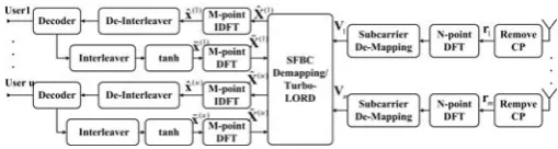
In this section, we consider the multiuser MIMO receiver of SC-FDMA system with Nr received antennas. Assume that perfect pulse shaping and channel state information (CSI) are achieved, and assume that all users access the base station in the same subband with power control such that all signals from mobile stations arrive at base station with the same average power. Then after removing CP, the received signal at the m-th received antenna denoted as rm in the time domain can be described as the summation of the circular convolution of channel impulse response hm,n with the transmit signal s(nu), the hm,n is assumed to be stationary within a symbol duration and known in the base station receiver. Figure 2 is the block diagram of the receiver. The received signal at the m-th receive antenna can be described as follows,
m U
u u m m
U
u N
n
u n u
n m m
t
q r q
s h
r
1
) (
1 1
) ( ) (
, (6)
where
mn mn mn
Tu n
m h , (0) h , (1) ... h , (L 1) )
(
,
h is the
time domain channel impulse response with of order L
between the n-th transmit antenna and the m-th receive antenna for user u , denotes the N -point circular convolution and qm is complex additive white Gaussian noise (AWGN) with zero mean and variance N0I. The signal rm(u) is described as follows,
t t
N
n
u n u
n m N
n
u n u
n m u
m
1
) ( ) (
, 1
) ( ) (
, )
( h s H s
r (7)
where the channel matrix (,) u
n m
matrix with first column equal to the N1 vector
TL N T u
n
m
( ) 1 ) ( , 0
h . After the N-point DFT operation and subcarrier de-mapping, the signal is described as follows,
m U u N n u n u n m m N U u N n u n u n m N m U u u m N m t t η S Λ q F s H F q r F V
1 1 ) ( ) ( , 1 1 ) ( ) ( , 1 ) ( (8)The circulant matrix (,) u
n m
H has the following properties N u n m H N u n
m F Λ F
H ( )
, )
(
, (9)
where ( ,) u
n m
Λ is a diagonal matrix with diagonal entries equal to the DFT of the channel impulse response. That is,
) ( , u n m
Λ is defined as
(0) ... ( 1)
0 ) ( , ) ( , ) ( 1 ) ( , ) ( , N H H diag N diag u n m u n m T L N T u n m N u n
m F h
Λ
(10)
Assume that the coherent bandwidth is much larger than the sub-carrier bandwidth, therefore the subchannels in neighborhood have almost the same frequency responses. That is, we can make the approximation that
) ( , ) ( , ) ( , ( ) ( ) u n m u n m u n
m H H
H where and are subcarrier index in the same designated band. After subcarrier de-mapping, we consider the 22 Alamouti SFBC scheme with 2 users in the same subband, the received signal can be written as follows,
1 2 , 1 )* 2 ( 2 ) 2 ( 2 , 1 )* 2 ( 1 2 ) 2 ( 1 , 1 )* 1 ( 2 ) 1 ( 2 , 1 )* 1 ( 1 2 ) 1 ( 1 , 1 1 2 , 1 2 , 1 ) 2 ( 1 2 ) 2 ( 2 , 1 ) 2 ( 2 ) 2 ( 1 , 1 ) 1 ( 1 2 ) 1 ( 2 , 1 ) 1 ( 2 ) 1 ( 1 , 1 2 , 1 i i i i i i i i i i i i X H X H X H X H V X H X H X H X H V (11) 1 2 , 2 )* 2 ( 2 ) 2 ( 2 , 2 )* 2 ( 1 2 ) 2 ( 1 , 2 )* 1 ( 1 2 ) 1 ( 2 , 2 )* 1 ( 1 2 ) 1 ( 1 , 2 1 2 , 2 2 , 2 ) 2 ( 1 2 ) 2 ( 2 , 2 ) 2 ( 2 ) 2 ( 1 , 2 ) 1 ( 1 2 ) 1 ( 2 , 2 ) 1 ( 2 ) 1 ( 1 , 2 2 , 2 i i i i i i i i i i i i X H X H X H X H V X H X H X H X H V (12) Arranging the above two equations in matrix format, we obtain 1 2 , 2 2 , 2 1 2 , 1 2 , 1 ) 2 ( 1 2 ) 2 ( 2 ) 2 ( 1 2 ) 2 ( 2 )* 2 ( 1 , 2 )* 2 ( 2 , 2 )* 1 ( 1 , 2 )* 1 ( 2 , 2 ) 2 ( 2 , 2 ) 2 ( 1 , 2 ) 1 ( 2 , 2 ) 1 ( 1 , 2 )* 2 ( 1 , 1 )* 2 ( 2 , 1 )* 1 ( 1 , 1 )* 1 ( 2 , 1 ) 2 ( 2 , 1 ) 2 ( 1 , 1 ) 1 ( 2 , 1 ) 1 ( 1 , 1 1 2 , 2 2 , 2 1 2 , 1 2 , 1 i i i i i i i i i i i i X X X X H H H H H H H H H H H H H H H H V V V V (13)
Combining the received signal at all received antennas, we have 2 1 ) 2 ( ) 1 ( ) 2 ( 2 ) 1 ( 2 ) 2 ( 1 ) 1 ( 1 2 1 η η X X H H H H V V (14) For the general case of SFBC with U users, each user employs Nt transmit antennas, K frequency transmit diversity, and M receive antennas in the base station, the above equation can be extended as follows
M U U M M M U U M η η η X X X H H H H H H H H H V V V 2 1 ) ( ) 2 ( ) 1 ( ) ( ) 2 ( ) 1 ( ) ( 2 ) 2 ( 2 ) 1 ( 2 ) ( 1 ) 2 ( 1 ) 1 ( 1 2 1 (15)
The equation (15) can be simplified as
η
HX
V (16)
where V is a MK1 matrix, H is a MKNtU matrix, X is a NtU1 matrix and η is a MK1 matrix. Next, we
employ the LORD algorithm to perform the turbo MUD. The LORD [12] algorithm consists of two steps:
1) Preprocessing: The transformation is similar to a QR decomposition but it can be completed without any normalizations.
2) Lattice Search: It provides parallelizable implementation that can easily generate reliable soft bit metrics.
The algorithm solves the Maximum Likelihood (ML) detection problem to estimate the users’ transmitted sequence
X, that is
2 )
( argmin
ˆ V HX
X X u (17) In [11] [12], the received signal can be split into real and imaginary parts,
TM M
r (V1) (V1) ... (V ) (V )
V (18)
Similar definitions hold for Xr and channel matrix Hr such that Vr HrXrηr. Then the channel matrix Hr is QR decomposed, corresponds to Gram-Schmidt orthogonalization (GSO) method without unnecessary normalizations, only requiring that the columns of Q be orthogonal, with arbitrary norm. So the received signal can be transformed into the following format,
η
X R V Q
V~ T r~ r~
(19) where R~ is the upper triangular matrix and Q is the orthogonal matrix. Once equation (19) has been obtained, simplified demodulation algorithms can be applied, the likelihood metric is
1 2 2 1 2 2 2 2 2 1 2 1 2 1 2 2 1 2 2 3 , 2 2 2 1 2 2 1 2 2 3 , 1 1 2 1 2 ) ( ~ ~ ... ~ ~ ~ ~ ˆ M i M M M M M M M j j j M j j j r u r X r V X r V X s X V X s X V T X R V X (20)The expressions for 2j , si,j, rj and more details are provided in [10]. Based on the above expression, we can employ the backward recursion algorithm that slices along all symbols for the lowest layers. Let Xˆ() be the collection of the decided symbols, the above likelihood can be expressed as a function of the two lowest layers,
M M
M M
u
r T X X X X
T 2 1 2 2 1 2
) ( ) ( , , ˆ
ˆ X
X (21)
The method, through an extensive search over each pair, detects the symbol close to that of ML detection. A Maximum-A-Posteriori (MAP) detector accepts the received vector and the a priori information, coming from the decoder, and evaluates the likelihood of each user’s possible transmitted symbols. It can be easily identified in the following metric,
U u N n u u n u b i X b N 1 2 1 ) ( ) ( 0 2 ) ( 2 1 ˆ X V HX (22)
( )1 ) ( : ) ( 1 ) ( :
1 ) ( :
) ( 1
) ( :
) (
ˆ max ˆ
max
ˆ exp
ˆ exp ln
u X
b u X
b
X b
u X
b
u
t
n n
n n
n
X X
X X
X X
X X
(23)
The Turbo-LORD [13] is based on a simplified but near optimal method to compute Max-Log-MAP approximation metric (22). The computation of (21) requires to take into account each possible constellation symbol. For this reason, useful re-organization of the data is required. Let Γ be the permutation matrix, the received signal can be rewritten as follows,
η
X
HΓΓ
n X
HΓΓ
V 1 T
(24) It is convenient to perform the QR decomposition of the channel matrix H, that is
QR
HΓT
(25) The first term in (22) can be written as
0 2
0 2
0 2
' '
N N
N
RX V
QRΓR
V HX
V
(26) where V'QHV,X'ΓX . We need to seek the best candidate according to the distance criterion and the “a priori” probability criterion that can be described as follows,
2 2
)
( argmin argmin ' '
ˆ V HX V RX
X
X
X
u
d (27)
U
u N
n
u u n
u b
a b X n
1 2
1
) ( ) ( )
(
min arg
ˆ
X
X (28)
The signal is then processed by the inverse DFT (IDFT) operation, we then have the time domain estimate
u u u
Tu
M x x
xˆ 0 ˆ 1 ... ˆ 1
ˆ( ) ( ) ( ) ( )
X which is defined
for 1uU as xˆ(u)FMHXˆ(u). Finally, de-interleaving and decoding are performed to recover the original data estimate. Figure 3 is the system block diagram of the proposed receiver. We propose to utilize turbo principle that combines MAP detection to perform multiuser detection. In this approach, the multiuser detector utilizes the extrinsic information from MAP decoder to cancel the interference from other users to improve the receiver performance. The decoder outputs not only provide hard bit decisions, but also the extrinsic information of all coded bit, including information and parity bits, which is used as “a priori” knowledge at the detector (after interleaving). Using independent “a priori” information for each bit of X(u), we obtain
1 1ln ( )
) ( )
(
u
n u n u
X b P
X b P n
(29)
where bn
X(u)
1 is the n- th bit of the symbol ) (uX , with n1,2,...,2Nb, where Nb log2
M /2 is the number of bits per dimension. The soft estimate of the transmitted data is as follows,
/2
tanh
1 1
~
) (
) ( )
(
) ( ) ( )
( ) (
n X P X
P
X P X X
x
u
u u
u u u
u
E
(30)
Performing DFT operation over ~x(u) , we have the expected values of each user’s frequency-domain data as follows,
~ (0) ~ (1) ... ~ ( 1)
DFT
) 1 ( ~ ... ) 1 ( ~ ) 0 ( ~
) ( )
( ) (
) ( )
( ) (
M x x
x
M X X
X
u u
u
u u
u
(31) At the beginning of the iterative process, no “a priori” information is available, so t(u)
n 0. In the successive iterations, Z(u) denotes the received signal which has all other users’ interferences being removed. That is) ( )
(u V HX~ u
Z (32)
When the iterative process converges, the bit reliability provided by the decoder increases and the soft estimates become closer to the true transmitted values [21].
IV. SIMULATION RESULTS
In this section, we demonstrate the performance of the proposed iterative multiuser MIMO detector for SC-FDMA system. The employed MIMO technology for the simulations is the 2×2 Alamouti SFBC. The adopted channel model is the spatial channel model (SCM) proposed in [20]. The channel is simulated over suburban area with vertical polarization antenna in microcell. In this system, each user is with two antennas for transmitter side, and receiver side has two antennas. The antenna spacing at base station is 6 wavelengths, while mobile station antenna spacing is 0.4 and 2 wavelengths. The simulated Turbo coded MIMO SC-FDMA systems has M8, N256 and the Cyclic Prefix (CP) length is 20. The employed encoder is the recursive convolutional codes (RSC) with code rate R1/2, under three different channel encoder (2, 1, 2), (2, 1, 3) and (2, 1, 4) where the last entry denotes the memory order m, and the constrained length is m+1. The employed interleaver is random interleaver. The algorithm for the turbo decoder is the BCJR algorithm.
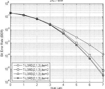
can cancel the interference for multiuser MIMO system. The performance of the T-LORD receiver outperforms the turbo MMSE receiver at BER=102. We also find that the T-LORD performance with mobile antenna space equal to 2 is better than that with antenna space equal to 0.4 at BER=102 when (2, 1, 4) convolutional code is used. Figs. 8-9 depict the bit error rate (BER) performances of the T-LORD detector for iterative multiuser MIMO SC-FDMA systems and the antenna spacing for mobile station equal to 0.4 and 2, respectively. The number of user is u1. As we can see, increasing the number of iterations, the proposed receiver further improves the BER. We also find that the T-LORD performance with mobile antenna space equal to 2 is 0.7 dB better than that with antenna space equal to 0.4 at BER=103.
V. CONCLUSION
By combining MIMO techniques with the SC-FDMA modulation scheme, MIMO SC-FDMA systems can achieve high data rates over broadband wireless channels. In this paper, we employ the SFBC on each transmitted block for the multiuser scenario. At receiver side, in order to reduce the searching complexity, we use the LORD algorithm and combine the turbo decoding to develop the low-complexity turbo LORD MUD for MIMO SC-FDMA systems. The proposed multiuser detection method performs iterative equalization and can effectively cancel MAI when there is limited number of users in the same subband or adequate receive antennas at the base stations. Moreover, the simulation results show that the performance of the proposed Turbo LORD receiver outperforms the turbo MMSE receiver.
REFERENCES
[1] T. Gonsalves and K. Itoh, “Multi-Objective Optimization for Software Development Projects,” in Lecture Notes in Engineering and Computer Science: International Multiconference of Engineers and Computer
Scientist 2010, pp. 1–6.
[2] H. G. Myung, J. Lim and D. J. Goodman, ‘‘Single Carrier FDMA for uplink wireless transmission,’’ IEEE Vehicular Technology Magazine, vol. 1, pp.30-38, Sep. 2006.
[3] Q. Li, G. Li, W. Lee, M. Lee, D. Mazzarese, F. Clerckx and Z. Li, ‘‘MIMO Techniques in WiMAX and LTE: A feature overview,’’ IEEE
Communications Magazine, vol. 48, no. 5, pp. 86-92, May 2010.
[4] H. Jafarkhani, SPACE-TIME CODING: THEORY AND PRACTICE, Cambridge university press, 2005.
[5] C. Ciochina, D. Castelain, D. Mottier and H. Sari, ‘‘Space-frequency block code for single-carrier FDMA,’’ IEEE Electronics Letters, vol. 44, no. 11, May 2008.
[6] C.-W. Tan and A. R. Calderbank, “Multiuser detection of alamouti signals,” IEEE Transactions on Communications, vol.57, no.7, pp.2080,2089, Jul. 2009.
[7] H.V. Poor, “Iterative multiuser detection,” IEEE Signal Processing
Magazine, vol.21, pp.81-88, Jan. 2004
[8] M. Tüchler, R. Koetter and A. C. Singer, “Turbo equalization: principles and new results,” IEEE Transactions on Communications, vol.50, no.5, pp.754,767, May 2002
[9] X. Liu, X. He, W. Ren and S. Li, “Evaluation of Near MLD Algorithms in MIMO SC-FDMA System,” International Conference on Wireless
Communications Networking and Mobile Computing, vol., no., pp.1,4,
23-25 Sept. 2010
[10] M. Sellathurai and S. Haykin, “Turbo-BLAST for wireless communications: theory and experiments,” IEEE Transactions
on Signal Processing, vol.50, no.10, pp.2538-2546, Oct. 2002.
[11] L. G. Barbero, T. Ratnarajah and C. Colin, “A low-complexity soft-MIMO detector based on the fixed-complexity sphere decoder,” in Proc. IEEE International Conference on Acoustics, Speech and Signal
Processing, vol., no., pp.2669-2672, March 2008
[12] M. Siti, and M. P. Fitz, “Layered orthogonal lattice detector for two transmit antenna communications,” in Proc. Allerton Conference on
Communication, Control, and Computing, Sep. 2005.
[13] M. Siti and M. P. Fitz, “A Novel Soft-Output Layered Orthogonal Lattice Detector for Multiple Antenna Communications,” in Proc.
IEEE International Conference on Communications, vol.4,
pp.1686-1691, Jun. 2006.
[14] A. Tomasoni, M. Siti, M. Ferrari and S. Bellini, “Low Complexity, Quasi-Optimal MIMO Detectors for Iterative Receivers,” IEEE
Transactions on Wireless Communications, vol.9, no.10,
pp.3166-3177, Oct. 2010.
[15] A. Tomasoni, M. Siti, M. Ferrari and S. Bellini, “Turbo-LORD: A MAP-Approaching Soft-Input Soft-Output Detector for Iterative MIMO Receivers,” IEEE Global Telecommunications Conference, vol., pp.3504-3508, Nov. 2007.
[16] A. Tomasoni, M. Siti, M. Ferrari and S. Bellini, “Hardware oriented, quasi-optimal detectors for iterative and non-iterative MIMO receivers,” EURASIP Journal on Wireless Communications and
Networking, Feb. 2012.
[17] S. H. Song, G. L. Chen, and K. B. Letaief, ‘‘Localized or interleaved? A tradeoff between diversity and CFO interference in multipath channels,’’ IEEE Transactions on Wireless Communications, vol. 10, no. 9, pp.2829-2834, Sep. 2011.
[18] S. M. Alamouti, ‘‘A Simple transmit diversity technique for wireless communications,’’ IEEE J. Select. Areas Commun., vol. 16, no. 8, pp.1451-1458, Oct. 1998.
[19] D. Gesbert, M. Kountouris, R. W. Heath, Jr., C.-B. Chae, and T. Salzer, “Shifting the MIMO Paradigm: From Single User to Multiuser Communications,” IEEE Signal Processing Magazine, vol. 24, no. 5, pp.36-46, Oct. 2007.
[20] S. Lin, and D. J. Costello, Error Control Coding, Pearson Prentice Hall, 2004.
[21] ‘‘Spatial channel model for Multiple Input Multiple Output (MIMO) simulations,’’ 3GPP, vol. TR 25.996, v. 10.0.0, Apr. 2011.
[22] A. Tomasoni, M. Ferrari, D. Gatti, F. Osnato and S. Bellini, “A Low Complexity Turbo MMSE Receiver for W-LAN MIMO Systems,” IEEE International Conference on Communications, vol.9, pp.4119-4124, Jun. 2006.
Figure 1: The transmitter of the multiuser MIMO SC-FDMA systems.
[image:5.595.303.558.662.730.2]Figure 2: The receiver of the multiuser MIMO SC-FDMA systems.
Figure 4: BER performance of the T-LORD and turbo MMSE with non-iterative multiuser detection for single user (MS antenna space 0.4).
Figure 5: BER performance of the T-LORD and turbo MMSE with non-iterative multiuser detection for single user (MS antenna space 2).
[image:6.595.56.240.244.400.2]Figure 6: BER performance of the T-LORD and turbo MMSE with non-iterative multiuser detection for two users (MS antenna space 0.4).
Figure 7: BER performance of the T-LORD and turbo MMSE with non-iterative multiuser detection for two users (MS antenna space 2).
Figure 8: BER performance of iterative MIMO receivers for SC-FDMA systems with single user (MS antenna space 0.4), and encoder is (2,1,3).
[image:6.595.315.498.245.403.2] [image:6.595.56.240.445.603.2] [image:6.595.314.500.447.604.2]