Quantitative analysis of ATM safety issues using
retrospective accident data:
the Dynamic Risk Modelling Project.
Maria Chiara Leva1, Massimiliano De Ambroggi1, Daniela Grippa2, Randall De Garis2, Paolo Trucco1, Oliver Sträter2
1
Politecnico di Milano, DIG Piazza Leonardo da Vinci 32, Milan Italy
2
Eurocontrol, Bruxelles Safety and Security Management (DAS-SSM) Bruxelles Belgium Contacts of the corresponding author:
Maria Chiara Leva1
Phone +39 0223994053 Fax: +39 0223994067
Abstract
The Dinamic Risk Modelling was a research project aimed at developing a simulation approach able to provide a quantitative analysis of some critical activities of Air Traffic Control (ATC) operators considering the organizational context in which they take place, the main cognitive processes underneath, and the possibility to inform the analysis using retrospective accident data.
The pilot study was aimed at providing an overview of possible opportunities related to the use of a cognitive simulator within the Eurocontrol framework called CONOPS (which is a detailed description of future operational concept for Air Traffic in Europe). The approach chosen within the field of HRA (Human Reliability Analysis) made use of a cognitive Simulator (named PROCOS), developed by Politecnico di Milano. The simulator in fact was built based on an Information Processing Level very much compatible with the one embedded in a method used by Eurcontrol for collecting accident data named HERA.
The pilot application was able to modify the calibration process of the simulator and make use of the retrospective accident data that was available.
The resulting approach can interact with standard risk assessment methodologies in order to analyze the criticalities arising from human performance in the ATC working contexts in the light of past experience.
Key words: cognitive simulation; human reliability analysis; Air Traffic Control; Dynamic Risk Modeling.
1. Introduction
Regarding the retrospective analysis of incidents, a research project has been set up at Eurocontrol that reviewed the theoretical and practical literature to determine the best conceptual framework upon which to base an ATM incident analysis tool. The conceptual framework chosen is that of human performance from the perspective of information processing (Isaac et al., 2002).
In order to exploit the data for prospective assessment, the approach of HERA-Predict (Isaac et al., 2004) was designed based on the experiences of using event data for safety assessment in nuclear power plants (Sträter, 2005). The lack of ad hoc data for the quantification process is in fact, one of the main issues affecting HRA applications in Air Traffic Management, the HERA-Predict approach is oriented towards tackling this issue. However the use of incident data for predictive purposes can be very difficult, especially if the prediction would like to refer to possible future scenario that differs from the one from which the data was collected.
Some data can be gathered in real time observations that can make use of virtual reality simulators for real operators to interact with, nevertheless there is a practical limit on the amount of human performance data that can be collected through virtual reality-based study; given that some human error probabilities are in the order of E-03 or even E-04, the amount of trials needed would be extremely high.
In this framework the development of a numerical simulator able to represent the performance of the controller or the team of controllers in a specified context can provide a useful mean for gathering data and analysis safety performance of a system. Such a simulator would be a cognitive one since it requires the capability to represent human performance. On the other side it should have the quantitative capability to produce a sufficient number of trials for gaining an estimation of Human Error Probabilities (HEP) that belong to the orders of magnitude mentioned above. One final requirement is that the tool should make use of retrospective accident data in calibrating its results.
Trucco and Leva (2007), developed a new cognitive simulator (PROCOS) for supporting human reliability analysis in complex operational context. The simulation model comprised two cognitive flow charts reproducing the behavior of a process industry operator. The flow charts were based on a model within an information processing perspective very similar to the one underpinning the HERA-PREDICT classification. Starting from this characteristics in the Dynamic Risk Modeling project it was then possible to modify the simulator in order to take into account a more detailed insight of the context of analysis (Air Traffic Management) and make use of the retrospective accident data suitable for the quantification process. The present paper introduces the main steps through which the project obtained its results.
2. The Use of Cognitive Simulation for HRA Prospective Analysis:
PROCOS
A cognitive simulation can be quantitative or qualitative. A qualitative simulation describes the evolution of a cognitive process, i.e. from the reception of an external stimulus to the subsequent action whereas a quantitative one is based on the structure of a qualitative one with the addition of a computational model for the human error probability assessment.
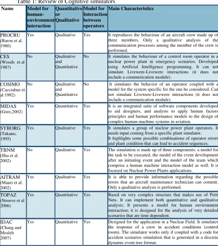
[image:3.612.89.522.215.705.2]The final outcome of a quantitative simulation can be the list of the types of actions or errors performed by the operator while executing a specific task or a probability value for each type of error, calculated through the simulation runs. Table 1 reports a brief summary of some of the main simulation projects developed in the past twenty years.
Table 1: Review of Cognitive simulators
Name Model for
human- environment interaction Quantitative or Qualitative Model for Interaction between operators Main Characteristics PROCRU (Baron et al. 1980)
Yes Qualitative Yes It reproduces the behaviour of an aircraft crew made up of three members. Only a qualitative analysis of the communication processes among the member of the crew is performed.
CES (Woods et al 1987)
No Qualitative
and Quantitative
No It simulates the behaviour of a control room operator in a nuclear power plant in emergency scenarios. Developed using Artificial Intelligence programming. It can not simulate Livewere-Livewere interactions (it does not include a communication module).
COSIMO (Cacciabue et al 1992)
No Qualitative
and Quantitative
No It simulates the behavior of an operator coupled with a model for the system specific for the one be considered. Can not simulate Livewere-Livewere interactions (it does not include a communication module).
MIDAS (Gore,2002)
Yes Quantitative Yes It is an integrated suite of software components developed to aid designers, and analysts to apply human factors principles and human performance models to the design of complex human-machine systems in aviation.
SYBORG (Takano, 1995)
Yes Qualitative Yes It simulates a group of nuclear power plant operators. It needs input coming from a specific plant simulator. It highlights some possible combinations of operator errors and plant condition that can lead to accident sequences. TBNM
(Shu et al. 2002)
No Qualitative Yes The simulation is made up of three components: a model for the task to be executed, the model of the event development after an initiating event and the model of the team which comprise a human machine interaction model as well. It is focused on Nuclear Power Plants applications.
AITRAM (Mauri et al. 2002)
Yes Qualitative Yes It is able to provide information regarding the possible errors that an aircraft maintenance technician can commit. Only a qualitative analysis is performed.
TOPAZ (Stroeve et al 2006)
Yes Quantitative Yes Based on very complex structure that makes use of Petri Nets. It can implement both quantitative and qualitative analysis; It presents a model for human environment interaction; it is designed for the analysis of very detailed scenarios that are time dependent.
IDAC (Chang and Mosleh 2007)
2.1 A semi static approach for a cognitive simulator
The simulator proposed in the present paper is based on a so called “semi-static approach”. The word “semi-static” indicates that the dynamism is focused on the cognitive simulation and, therefore, on the cognitive flow chart,while the operator actions are able to modify only the state of some equipment of the plant according to:
a limited set of the states in which the equipment can be turned;
the error mode identified through a previous analysis (in this case through HERA) and extracted as a result of the cognitive simulation of the operator;
an explicit relation between the actions outcomes (correct execution or Error modes) and equipment status modifications (the relation has been derived from a previous qualitative analysis).
Its focus is mainly in conveying a quantitative result, comparable to those of a “first generation” HRA method, taking into account a cognitive analysis of the operator as well.
As a further step the simulator considers the evaluation of error management as part of the overall assessment from the same cognitive point of view, differing from the way traditional human reliability methods (e.g. THERP) consider the recovery phase.
2.2 Cognitive Model of the operator in PROCOS
The model used for configuring the flow chart representing the operators is based on a combination of PIPE (Cacciabue, 1998) and SHELL. PIPE represents the process of human cognition according to the “Minimal Modelling Manifesto” (Hollnagel, 1993). The PIPE model is in fact based on the four main cognitive functions:
- Perception; - Interpretation; - Planning; - Execution.
The cognitive functions are influenced or triggered by input parameters such as hardware stimuli and context stimuli. The human cognitive path followed through these functions leads to a response (output). The cognitive process involved makes use of the memory/knowledge base and allocation of resources of the individual.
The role of PIPE in the simulator entails the structure of the flow chart representing the main possible cognitive processes that an operator could perform in order to perform an action.
The development of flow charts for representing the cognitive process is within a “information processing perspective” and it could be a good approach for case studies where the tasks to be analyzed are highly proceduralised. Furthermore it presents the advantage of mapping the possible information and decision making processes in an intuitive way that can be followed and revised even from external reviewers.
The taxonomy chosen for describing possible erroneous outcomes of a human performance in the simulator relates to the “presumed origin of an error within the stages involved in conceiving and then carrying out an action sequence” (Reason, 1990), they are therefore called “Error Types”. They are classified according to Wickens (1992).:
Error in Perception: errors regarding issues related to the picking up and understanding of information;
Error in Memory: errors related to both short-term storage and more permanent information based on the person’s training and experience;
Error in Decision: errors related to the judgment and decision making process required to the operators;
Error in Response: it is sometimes possible to carry out actions that have not been intended, an example of this is often referred as a slip of the tongue.
2.3 Architecture of the simulator
The structure of the simulator is represented in Figure 1 and it is based on:
the Operator Module, which imply the cognitive flow charts for Action execution and Recovery phase, plus an error types/error modes matrix that puts in relation each error type category with a set of possible error modes (which are the analogous of the error details). A critical underlying feature of this module is the mathematical model for decision block criteria of the flow charts, since it is the engine of the stocasticity in the simulation;
the Task Execution Module, based on the Task Analysis referred to the procedure that has to be simulated;
the Human Machine Interface Module, made up of tables relating the hardware state with the operator actions (task executed or error modes committed).
The Inputs required for the simulation process are:
Contextual Conditions (CCs) affecting the task to be simulated;
hardware involved in the execution of the task and its possible states;
steps of the task (Task Analysis );
possible error modes to be considered.
Figure 1: Architecture of the simulator PROCOS
Table 2: Extract of the tabular translation of the task analysis flow-chart
Description Correct Error Type Execution E T Perception ET Interpretation Error Type Decision Correct EM1 EM2 EM1 EM2 EM1 EM2 EM1 EM2
e1
object on
runway yes: e2 no: e9
e9
visibility is good
yes:
ta16 no: ta17
ta16
ATCO verifies visually runway availability and issues landing
clearance e10
Not done: ta17
Not done: ta17
Warning clearance plan: ta24
ta17 ATCO verifies,using the radar, runway availability and issues landing
clearance e10
Not done: (Warning / Error) ta18
Other than: ta24
Warning clearance plan: ta24
ta18
ATCO issues the landing
clearance e10
Slip of the tongue:
The main Output of the simulator is to provide a probability value in respect of ATCs procedures executions identified as critical (with multiple trial generation) and a probability value for the corrective actions in the recovery phase as well. These probability values depend on the CCs, directly connected to the decision boxes of the flow charts through the decision block criteria. In this way it is possible to take into account a cognitive point of view in the Human Error Probability generation, enabling to consider a more formalized connection with the CCs, which are the key points for identifying organizational corrective or preventive actions.
The architecture of the simulator is centered on the flow chart of the cognitive process which in turn has its fulcrum in the decision blocks.
Each Decision Block has two possible exits: “Yes” and “No”. The exit process is stochastic and it depends on the CCs values and the influence they have on each decision block.
If we indicate with X the possible outcome of a decision Block, X is a Bernoulli’s variable and the following values are associated with X:
Yes X = 1 No X = 0
Then the probability density function fx(x) is equal to:
− = =
= =
−
otherwise x or x per p
p p x f x f
x x
x x
0
1 0 )
1 ( ) , ( ) (
1
(1)
where 0 < p < 1 and 1 – p = q.
The probability of having “Yes” as a possible exit of the block can be expressed as [P(X = 1)] and it is equal to p, while the probability of having the “No” exit is [P(X = 0)] equal to q. In order to calibrate each decision block, the value of p, that is the success probability of the cognitive process in the block, has been expressed as a function of the CCs involved for the same block.For a complete description of PROCOS approach features refer to Trucco and Leva (2007).
Figure 2: Extract of part of the cognitive flow chart used for representing Liveware- Hardware interaction
3 The trial application: selection and implementation of a case study
The trial application of a case study using PROCOS is aimed at calibrating the simulation process on data available by the analysis of past accident obtained using HERA retrospectively.
The trial application of the simulator was directed towards a case study developed within the ConOps framework (Eurocontrol, 2005). The framework identifies the functions and processes, and their corresponding interactions and information flows; concerned actors, their roles and responsibilities in possible future ATM European Operations. The case studies in Conops are normally referred as use cases and they serve to provide a more detailed elaboration of particular aspects of ATM possible scenarios, especially “what-if” situations (the alternative flows). The scenarios and use case selected for the trial application is: “Handle Aircraft Landing” (OATA-P2-WP3 2-1, 2004). It describes how a Tower Runway Controller manages the landing of an aircraft. It starts when the intermediary approach phase is completed and the aircraft is ready for the final approach and ends when the Tower Runway Controller is ensured that the aircraft has vacated the runway.
subtasks. The use case constitutes the base for the task analysis to be analysed through the simulator chosen for the trial application (PROCOS).
3.1 The PROCOS-ConOps Task Analysis
The use cases in ConOps are structured according to the following elements:
- Scope :
o System, black-box. System means an Overall ATM/CNS Target Architecture compliant system;
- Summary:
o This Use Case for instance, describes how a Tower Runway Controller uses the System to control the landing of an aircraft. It starts when the intermediary approach phase is completed and the aircraft is ready for final approach and ends when the Tower Runway Controller is ensured that the aircraft has vacated the runway;
- Actors:
o Description of the main actors involved;
- Preconditions:
o Scenario inputs to the analysis;
- Post conditions:
o Possible success end states; o Possible failure end states;
- Definitions:
o List of the main term and abbreviations used;
- Triggered:
o Elements that triggered the use case events (i.e.: the use case starts when the system detects that the aircraft is on final approach);
- Main Flow:
o Main path, or nominal path that should be followed by the chain of events that lead to a success end state;
- Alternative Flows:
o Possible deviations from the nominal path that can be recovered by following procedures;
- Failure Flows:
o Possible deviation from the nominal path that cause failures of the task.
It was then possible with little effort to translate the information already available in ConOps, given in the structure highlighted above, in a flow chart format. Following this first translation it has then been necessary to refine the level of detail provided with the one necessary to match the analytical capability provided by the cognitive model of the operator. The task, in fact, has to be broken down into single human actions (subtasks) whose outcomes are compatible with the level of detail of the information processing involved in the cognitive flowchart (e.g. single actions, single decision making processes, etc.).
The refinement process also involved some further specification of the possible criticalities arising form external conditions that may have not been specified in the use case (such as visibility conditions).
The process was carried out in conjunction with two experienced Air Traffic Controllers, one of which is also the developer of the ConOps Use Case considered.
All the possible exits of the sub-steps are to be monitored by the simulation process and the effects on and from the equipment involved in the task were to be explicitly considered; up to the level of detail required by the use case itself. The task analysis flow chart has been developed using MS Visio (MS Visio is also a compatible software for developing the task analysis in UML).
It is important to underline that the flow chart for the task analysis has not to be confused with the flow chart developed for the information processing activities of the operator (cognitive flow charts of the Operator Module). The first in fact is used for mapping the task or activity the operators are supposed to perform, considering all the possible deviations from the nominal path, while the cognitive flow chart represent the information processing model underpinning the single actions reported in the task analysis flow. To every decision blocks of the task analysis flow chart is assigned a certain exit (correct execution or error modes) according to the run of the cognitive flow chart underpinning it, which simulates the actual human execution of the single sub-steps. All the possible exits of the sub-steps are recorded together with the effects on and from the equipment involved in the task.
The Task analysis flow chart is made up of:
- the sub-steps constituting the human actions within the task. The exit of a sub-step is a correct action that in turn changes some equipment status and goes further to the next step, or an error mode that can constitute an irrevocable failure and therefore recorded as such and ends the simulation process; an error mode can also be “labelled” as a warning instead of irrevocable failure, thus it can then be followed by other actions. This is carried out in accordance with what has been already described in the use case and detailed then by the analysts (HF practitioners and experts of the field of analysis). Each possible error type and error mode outcome should be explored. In accordance with ConOps use cases, during the development of this project it has not been considered the effects from and on hardware equipments. Therefore a sub-step is defined by:
- code and description;
- type of actions (communication or action triggered by hardware stimuli); - type of cognitive path required for performing the sub-step (skill, role or
- all possible exits of the sub-step (correct or error type and error mode) with the following step. Visualisation of the sub-step within task analysis flow chart.
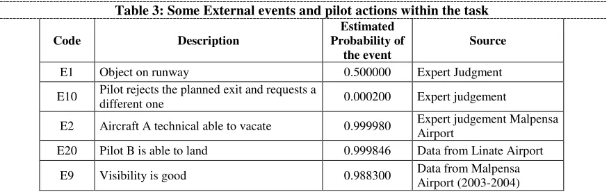
[image:11.612.95.524.506.689.2]- Events and pilot actions. This category comprises the possible occurrences of an external event (e.g. weather conditions), a technical failure on an aircraft that disables the plane to land as planned, or pilot actions (the pilot actions are not simulated referring to a cognitive model for the pilot because it was not considered to be in the scope of the preliminary application, whose focus was mainly on air traffic controllers). Events outcome are “Yes” or “No” exits (“Yes” the event takes place, “No” it does not take place), the probability density function according to which the events are generated in the simulation is Bernoullian. The assessment of the probability of occurrences of these events and pilot actions is based on historical data and experts’ judgements. Table 3 reports a list of some events and pilot actions identified as important during the development of the task analysis for the use case. The estimated probability of occurrence for each event is reported in the third left column of Table 3, while the last column reports the source of the probability estimation. In the task analysis the events are linked to the sub-task the operators have to undertake as a consequence of the new scenario setting introduced by them.
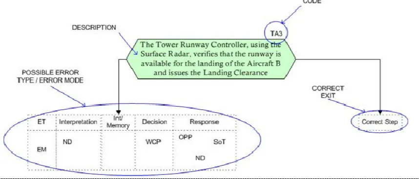
Figure 3 reports an example of a sub-step identified within the task analysis flow chart. The exit of the box highlighted in blue is a possible correct performance or a possible error. The outcome is decided by a run of the cognitive flow chart referring to the action of the sub-step, which, in this case, is under the Liveware-Hardware interaction part. The task analysis flow chart is then translated in a tabular format easier to be converted into the simulation code. An example of some sub-steps in the tabular format is reported in Table 2. The first column on the left is the Id of the element (“ta#” for a sub-step, “e#” for an event, etc.. ) followed by a column reporting a brief description of the task/event, The following columns report all the possible other actions/events that can follow the task/event in case it has a correct outcome or an error, for the event the outcomes are not correct or incorrect but simply yes-“it happens” no-“it does not happen”.
Table 3: Some External events and pilot actions within the task
Code Description
Estimated Probability of
the event
Source
E1 Object on runway 0.500000 Expert Judgment
E10 Pilot rejects the planned exit and requests a
different one 0.000200 Expert judgement
E2 Aircraft A technical able to vacate 0.999980 Expert judgement Malpensa Airport
E20 Pilot B is able to land 0.999846 Data from Linate Airport
E9 Visibility is good 0.988300 Data from Malpensa
Airport (2003-2004)
The simulator should be able to assess the probability of the deviations from the main flow by means of multiple trials. The task analysis and the sub-steps of which it is made of therefore constitute a very important input for the simulation process.
4 The Calibration Process of the decision blocks in PROCOS using
HERA Data
The taxonomy used by the simulator represented an advantage for the project because it matched the classification framework used for collecting the accident data.
Within Eurcontrol in fact, the retrospective analysis of incidents has been based on a conceptual framework of human performance that makes use of an information processing perspective. The technique and the related taxonomy are model-based. A model in fact “allows causes and their inter-relations to be better understood. An error model provides an ‘organizing principle’ to guide learning from errors. Trends and patterns tend to make more sense when seen against the background of a model and more ‘strategic’ approaches to error reduction may arise, rather than short term error reduction initiatives following each single error event.”. (Isaac et al., 2003)
The cognitive simulator (PROCOS) previously presented comprises two cognitive flow charts. The flow charts are based on a model within an information processing perspective very similar to the one underlying the HERA-Predict classification. Therefore, it has been possible to modify the simulator in order to take into account a more detailed insight of the context of analysis (Air Traffic Management) and obtain suitable data for a possible quantification process. The main factors to be described in order to classify and analyze errors in HERA are shown in Table 4.
Table 4: Main Factors to consider for analyzing human error with HERA (Isaac et al., 2003)
Taxonomy Description
Error
Error Type What keyword can be applied to the error (including rule breaking and violation), in terms of timing, selection or quality of performance or communication?
Error Detail (ED) What cognitive process was implicated in the error? Error Mechanism (EM) What cognitive function failed, and in what way did it fail? Information Processing Levels (IPs) How did the error occur in terms of psychological mechanisms?
Task What task(s) was/were being performed by the controllers(s) at the time that the error occurred?
Information & Equipment What was the topic of the error, the equipment used in the error or the information involved? (e.g. what did the controller misperceive, forget, misjudge, etc.?) What HMI element was the controller using?
Contextual Conditions (CCs) What other factors, either internal or external to the controller, affected the controller’s performance?
The model used as the main skeleton, is extensively based on the one proposed by Wickens (1992). The retrospective accident analyses in HERA, is carried out following several steps associated to specific flow charts. The steps are:
a. defining the Error Type;
b. defining the error or rule breaking or violation behavior through a flowchart. c. identifying the Error Detail through a flowchart;
d. identifying the Error Mechanism and associated information processing failures through flowcharts;
e. identifying the Tasks from tables:
f. identifying the Equipment and Information from tables;
g. identifying all the Contextual Conditions through a flowchart and tables.
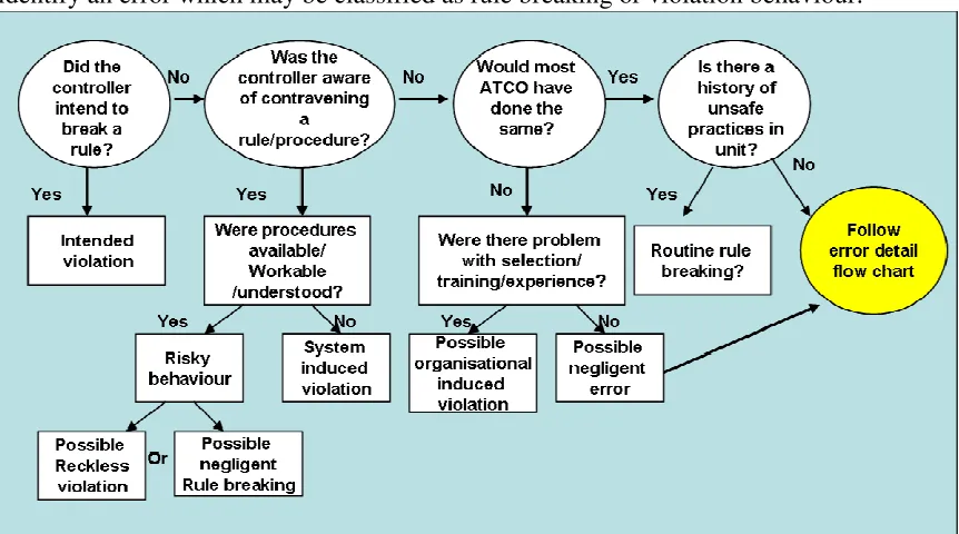
[image:13.612.91.522.394.634.2]An example of the flow chart used within HERA for providing guidance in the Error Type identification is reported in Figure 4, which illustrates how an HERA analyst would identify an error which may be classified as rule breaking or violation behaviour.
Figure 4: Guidance for Rule breaking and violations identification within HERA (Isaac et al., 2003)
important to highlight in the present paper is that the Information Processing Level and the Error Mechanism proposed in HERA (partly displayed by Figure 4) and the ones embedded in the structure of the simulator, both in the cognitive flow chart and in the task analysis one (see Figure 2 and 3), are very much compatible. Furthermore the steps listed above constitute steps for the preparation of the simulation runs as well, and are mainly captured as part of one of the most important activities preceding the application of the simulator, which is to say the task analysis.
4.1 The PROCOS-HERA calibration process: challenges and constraints
In order to adapt the simulator to the use of the HERA data some changes have been made. A particular decision block with a filtering action needed to be introduced in the cognitive flow chart (Figure 2) in order to distinguish between the possible cognitive paths required by steps that may involve some decision making process as opposed to the ones that are very frequently performed by ATCO following fixed rules; the exit of this decision block (called “frequent step”) is assigned in accordance with a check box to be used by the analyst during the specific task analysis.
The second major modification was the introduction of a better cognitive model for the communication among operators (Liveware-Liveware interaction), able to capture the processes and the possible deviations underpinning the “instruction-readback-hearback” procedures in a normal daily operation of the air traffic controllers and of the pilots. Furthermore the cognitive flowcharts used for the first application of PROCOS have been modified in order to take into account the error type “violation” of HERA which was not yet included.
[image:14.612.87.525.586.711.2]As already said the trial application of a case study using PROCOS was mainly aimed at verifying the possibility of calibrating the simulation process on the data coming from the analysis of past accident using HERA retrospectively. The first step was the identification of the correspondences between PROCOS calibrated decision blocks and the Error Types (and Error Modes) reported in HERA. The correspondences have been identified with the help of an HERA practitioner. The criteria adopted for the identification was the match between the error type category underlying the decision block (according to Wickens taxonomy) and the error types of HERA that could be referred to it. Table 5 reports some Blocks of the Cognitive Flow Charts (on the extreme left column) and the possible correspondent error types in the HERA taxonomy (identified on the extreme right column).
Table 5. Example of the correspondence between decision blocks and HERA error types
ID Block Description Block type Possible HERA correspondent ET
PV-IP: Association Bias
PV-EM: Misidentification of information PV-IP: Information overload
PV-EM: Misreading of information 3 Recognize stimuli calibrated decision block
PV-EM: Misperception of information PV-IP: Information overload PV-IP: Expectation Bias 5 Visual Perception of alerting info
(visual only) calibrated decision block
PV-IP: Visual/Sound confusion background info
PV-IP: Information overload PDM-IP: Incorrect assumption PV-IP: Association Bias
PV-EM: Misidentification of information PV-IP: Discrimination Problem PV-IP: Information overload 7 Correct HW interpretation calibrated decision block
PDM-IP: Failed to recognise risk
The probability density function of the variable representing the exit of the decision block is bernoullian and therefore fx(x) is equal to the one proposed in equaton (1). For the
present application, the procedure for estimating, for each Decision Block, the value of q in equation (1) has been derived using the HERA Dataset provided by Eurocontrol. Indeed, the data available can provide indications for the rate of occurrence of specific error types and also for the role played by Contextual Conditions in a certain event where a certain type of error occurred. The HERA dataset used for this application has the following characteristics:
- Number of recorded accident/near miss events: 62
- Number of recorded ACTO errors: 91
- Perception & Vigilance 38
- Memory 7
- Planning & Decision Making 36
- Response Execution 10
- Number of recorded occurrences of Contextual Conditions (CCs): 130
- Number of movements during the reporting period: 4 million(estimated)
- Level of analysis of Contextual Conditions: Main Categories
In HERA the Contextual Conditions (CCs) are defined as “factors, internal or external to the controller, which influence the controller’s performance of ATM tasks. Contextual Conditions (CCs) can help to explain why the error occurred.” The set of CCs used in HERA was developed from an analysis of UK AIRPROX reports, discussions with Air Traffic Controllers and the human factors literature (Isaac et al., 2003).
The main categories of Contextual Conditions available in the HERA taxonomy are: 1. Pilot-Controller Communications;
2. Pilot actions;
3. Traffic and airspace; 4. Weather;
5. Documentation and procedures; 6. Training and experience; 7. Workplace design and HMI; 8. Environment;
9. Personal Factors; 10. Team factors;
11. Organisational factors.
Table 6. Example of specific CCs considered for three of the main categories within HERA
CONTEXTUAL CONDITIONS (CCs)
Training and experience
Inadequate knowledge for position Inadequate experience on position Inadequate time on position Unfamiliar task in routine operations Novel situation
Over training
Inadequate mentoring
Inadequate On-the-Job Training (OJT) Inadequate emergency training
Inadequate Team Resource Management (TRM) training Inadequate recurrent/continuation training
Controller under training
Controller under examination/check Other – State:
Team factors
Controllers on the floor assisting one another with the traffic Currency and availability of all necessary equipment Position relief briefing
Cooperative effort to accommodate the flow of traffic Team relations – conflicts / personality problems Late returns to the position after breaks
Positions left temporarily unstaffed New or temporary team assignments Lack of responsibility
Unclear working methods Confidence in others Team pressures
Cooperation from supervisors from other areas in traffic flow initiatives Support from others - flight data / maintenance
Management provision of resources and assistance as dictated by the traffic needs
Support from other units
Staffing for the traffic requirements
Confidence in supervisor’s ability to manage the air traffic activity Supervisory cooperation to manage the traffic during this shift Management cooperation to assist and support the sectors/positions/ areas/facilities
Higher management cooperation to assist and support the sectors/positions/areas/facilities
Other – State:
Organisational factors
Work environment
Safety versus efficiency – for yourself / organisation Numbers of qualified controllers
Job satisfaction Roster/rest duty times Work scheduling
Adherence to rules by ATCOs Adherence to rules by supervisors Terms and conditions of work
In the HERA accident data set used for the pilot study however, the specific CCs taken into account were not detailed and only the main categories were reported. Furthermore it is important to note that in HERA the interdependences among CCs were not explicitly considered and the data available was not sufficient to estimate the correlations among them.
For the trial application PROCOS fully adopted the HERA CCs taxonomy with its current limitations so as to fully comply with the current data availability. The procedure for evaluating the q probability of the bernoullian law for the Decision Block was based on an ogivian-shaped curve expressed by the formula of Rasch (1980):
n i n i s r s r i type of Failure
e
e
P
µ µ − −+
=
1
(2) Where:ri = Percentage of errors in a situation given all situations of the same type in the data
base;
µ= 0.5; the adjustment of the location of the crossing point (0.5 assigns rational processing);
sn= 0.075; empirical parameter to adjust the slope of the ogivian curve;
e= natural exponent (2.718).
Equation (2) has been proposed by Sträter(2005) for relating the absolute HEP=n/N with the empirical data collected by accident databases. In a method named CAHR, Sträter (2000) found that the Rasch equation was revealed as the closest line to approximate the relation between the percentage of errors in a certain situation given the number of situations of the same type in the database, and THERP data about absolute probability for a given type of error.
As an assumption, it was then decided to use the Rasch equation for describing also the relation between the FLI and ri, where FLI is the Failure Likelihood Index.
'
n
s
µ
'
FLI
e
'
n
s
µ
'
FLI
e
i
r
−
+
−
=
1
(3)The weight of the effect that the CCs can have on the situation is seen on a negative perspective, which is to say it takes into account only those Contextual Conditions whose presence negatively affect the performance of a human operator.
∑
=⋅
=
j N i i iy
w
FLI
1)
(
(4)wi = normalised weight of the i-th CC for the cognitive process of the j-th block
yi = i-th CC –value, i.e. a measure of the intensity or extent of presence of the i-th CC.
Nj = number of CCs for the j-th block
and
∑
= = j N i i w 1 1
Equation 3 needs to be calibrated, that is for each Decision Block of the Cognitive Flowchart we need to identify the parameters
µ
’ and sn’ using the empirical data availablein the HERA Database. Three anchor points were fixed.
= = −3 10 0 i r FLI
which represents the ideal working conditions;
= = 9 , 0 1 i r FLI
which represents the worst possible working conditions;
* * i r FLI
which represents the “nominal” working conditions extracted from HERA data. The calibration procedure is set out in the following steps:
a) The ri* value is obtained through formula
ev i ev i N n
r*= (5)
Where:
i ev
n is the number of events that have at least an occurrence in the set of HERA Error Types linked to the decision block (number of events linked to the block);
ev
N is the total number of “accident/near miss” events in the dataset;
b) The contextual conditions linked to the block are identified (experts’ judgments, and empirical data are used jointly);
c) The weight of CCi is estimated as the probability of having an Error Type (linked to
the decision block) given the occurrence of the i-th Contextual Condition; it is in fact possible to demonstrate that
CCi k CCi i N N w = Where: k CCi
N is the number of occurrences of CCi in the events linked to the decision block;
CCi
N is the total number of occurrences of CCi in the database.
wi is then normalized:
d) Finally, an empirical mean value for FLI is calculated that refers to a specifics ri (ri*)
for the events linked to the decision block under calibration;
e) Using the three couples of value for FLI and related ri:
- ( 0 , 10-3 ): optimal situation in which there are no Contextual Conditions; - ( FLI* , ri* ): nominal situation extracted from the HERA database;
- ( 1 , 0.9 ): the worst situation in which all Contextual Conditions are present at the same time.
it is possible to find the two parameters
µ
’ and sn’ for the Rasch equation (3) byapplying the least square method. Experts’ judgements are used as a second source for estimating the importance (wi) of each CC.
4.2 The use of experts’ Judgments for the confidence interval of Contextual Conditions.
To gather information about the absolute contribution of each Contextual Condition (CC) to the possible incorrect execution of a task performed by an Air Traffic Controller, a questionnaire has been addressed to some Air Traffic Controllers who are involved in the specific task. Twenty-nine Air Traffic Controllers, coming from different country and different airports, have been interviewed. The values collected are then used for establishing the range in which the mean value of the importance of each CC can actually vary. For each CC in fact, given the mean obtained from the HERA dataset and the value obtained from the interviews it is possible to calculate the sample mean and the sample variance of the CC weight.
Therefore, we can obtain a 100*(1- α) percent confidence interval for the mean value of
the weight, which is:
n s t w n
s t
wi i
2 2
α α ≤
µ
≤ +− (10)
This provides an interval within which the value of the CC weight in question lies during a specific simulation run. After the percentage of the confidence interval is chosen, in fact, the value of wi of each simulation run will be extracted within the related range of values.
Therefore at each run the weight of each CC is randomly extracted by its related interval (assuming a uniform distribution). This values are then used for evaluating the FLI (equation 4), taking into account that the presence of the CCs depends on the scenario that we want to simulate, and the correspondent ri by means of equation 3. This value of
ri is then substituted into the ogivian-shaped curve expressed by Rasch equation (2) and
5. Results of the simulation campaign
5.1 Setting the simulation campaign
The simulation campaign for the trial application was organised into the following settings:
- Number of scenarios: 4
- Number of experiments for each scenario: 20
- Number of simulation runs for each experiment: 106 movements
For the trial application in fact only four basic scenarios have been selected. They refer to the possible different impact of the main category of Contextual Conditions. The CCs have been taken into account in a Boolean logic scheme: if the value is 0 the CC is not playing a role in the simulation scenario, while if the assigned value is 1 it is negative influencing the operator performance in the simulation scenario. The rationale behind the choice of the four scenarios lays mainly in the purpose of verifying the consistency of the simulator results.
- scenario S1: any CC is considered and ideal conditions are postulated, thus this is the best scenario from an ATCO point of view (base case);
- scenario S2: only the external Contextual Conditions play a negative role in the simulation;
- scenario S3: only Contextual Conditions expressing human and internal organizational factors play a negative role in the task execution;
- scenario S4: it is the worst possible scenario where all the Contextual Conditions are considered at their maximum potential negative affect on the ATCO performance.
For each scenario, different ranges of Failure Likelihood Index (FLI) have to be simulated corresponding to the different contributions that different sets of CCs have on the FLI value. As already shown in section 4 of the present paper the CC weight is extracted from confidence interval considered for the mean value of the weight (equation 10). At each run the weight of each CC is randomly extracted by its related interval assuming a uniform distribution. These values are then used for evaluating the FLI (equation 4), taking into account that the presence of the CCs depend on the scenario under study.
5.2 Number of repetition of simulation runs
The aim of this project is to estimate a Human Error Probability (HEP) that, in the nominal case where Contextual Conditions do not play any negative role, we expect to be not higher than 10-3.
Some uncertain events generated during the execution of the simulated task – i.e. handling of the aircraft landing - have probabilities of occurrence between 10-4 and 10-5; thus, some branches of the task flowchart have a very low probability of occurrence. In order to have a meaningful number of occurrences for any branch of the task and according to an empirical rule that suggests to set a number of runs at least of one order of magnitude higher than the lower probability of occurrence, it has been decided to perform one million runs for each simulation experiment, corresponding to one million landings on the runway. Finally, considering the available time for performing the entire simulation campaign, it has been decided to execute 20 experiments for each scenario to build significant statistics.
5.3 Collection and processing of simulation
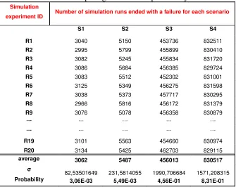
[image:21.612.140.475.442.708.2]The results of the simulation were assembled and processed in different ways to calculate different statistics. First of all, the probabilities of correct or failed and state for the task were estimated. For each scenario, the mean value and the standard deviation of the probability of occurrence of correct/failed task were calculated for the assessment of the probability of correct task. The total probability of a failed task is the complement to 1, but it is important to remember that different failure end states of the task are considered and not all of them are irrevocable failures, some of them are simply warning errors, or a failure of the task due to an incorrect action of the pilot. Thus it was necessary to analyse the different exits from the task (Figure 5) in order to distinguish between the irrevocable and not irrevocable (warning) failures.
Table 7: Table used for computing the absolute probability of a correct task
Simulation
experiment ID Number of simulation runs ended with a failure for each scenario
S1 S2 S3 S4
R1 3040 5150 453736 832511 R2 2995 5799 455899 830410 R3 3082 5245 455834 831720 R4 3086 5684 456385 829724 R5 3083 5512 452302 831001 R6 3125 5349 456275 831598 R7 3038 5373 457717 830295 R8 2966 5816 456172 831379 R9 3076 5078 456358 830879
… … … … …
… … … … …
R19 3101 5563 454660 830974 R20 3134 5425 462703 829115 average 3062 5487 456013 830517
σ σ σ σ
(movement)
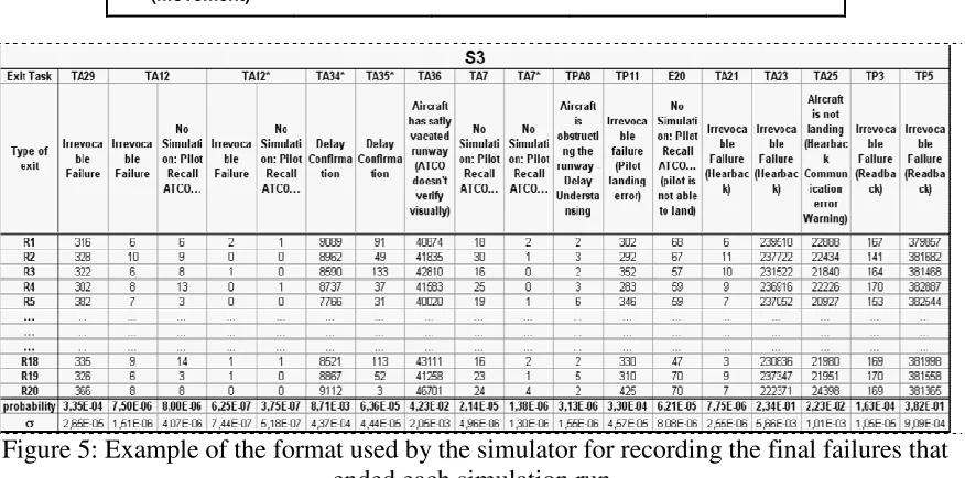
Figure 5: Example of the format used by the simulator for recording the final failures that ended each simulation run.
[image:22.612.104.525.386.641.2]The exits of the task were ranked considering the magnitude of their potential negative consequences as reported in Table 8.
Table 8: Ranking of the possible exits of the simulated task according to the magnitude of potential negative consequences.
Type of exit Exit task
ATCO doesn't issue the instruction. Pilot recalls ATCO and requests the instruction (no simulation)
TA7 TA7* TA7** TA12 TA12* TA13
Aircraft has safely vacated runway but there is a Delaied
Confirmation by ATCO TA31 TA32 TA34* TA35*
Aircraft has safely vacated runway (ATCO doesn't verify
visually) TA36
Aircraft is obstructing the runway – Delay in Understanding TPA8
Irrevocable failure
TA29 TA29* TA12 TA12* TA21 TA22 TA23 TA30*
TP3 TP4 TP5 TP6
Two more “failure end states” of the task refers to actions of the pilot:
Pilot is not able to land and calls ATCO… No Simulation E20
Pilot landing error (Irrevocable failure due to pilot action) TP11
- Recovery by procedure: it is placed at the task analysis level and represents the possible recovery procedure described as a “deviated” path within the task analysis;
- Recovery by clarification: it is placed at the cognitive flowchart level and represents the recovery capabilities provided by the communication process. For each scenario, the average of occurrences of recovery actions and the average of occurrences of correct recovery for both “by procedure” and “by clarification” were recorded. Then the absolute probability of recovery action [recovery/movements] and the absolute probability of recovery failures [failures/recovery] were calculated.
After the analysis of the task, the occurrences of single error types have been analysed. Each probability is referred to the number of movements and then, using an estimate of number of movements in one year, it is also possible to refer the error probability to the operational time. In order to conclude the analysis of the results and to prove the stochastic nature of the simulation a normality test on the results has been conducted.
5.4 Discussion of the results of the case study
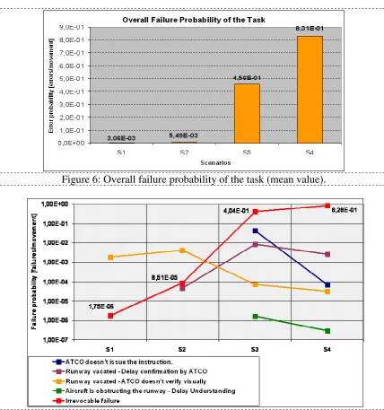
One of the results obtained shows how the failure probability of the task increases as the conditions of the scenario worsen, which is an assurance about the general consistency of the simulator results. The relationship between the number of Contextual Conditions (CCs) that affect the scenario and the value of the failure probability is not linear; namely, there is not a linear dependency between the number of CCs and the failure probability, but the increase from a scenario to another one depends on the weight of the Contextual Conditions that play a role within those scenarios. Specifically, Figure 6 indicates that the human and organisational factors (scenario S3) have a stronger impact than the external contextual conditions (scenario S2) on the performance of the ATCO. Indeed, compared to the base case (scenario S1), the failure probability of the task increases by two orders of magnitude when the human and organisational factors negatively affect the ATCO, while the order of magnitude of the failure probability remain the same also when all the negative external conditions are considered.
One last consideration can be made regarding the overall failure probability of the task. When the air traffic controller works in the best conditions (scenario 1), the failure probability of the task is not zero but 10-3. This value might appear high but Figure 6 shows that the probability to have an irrevocable failure is only 10-6. Another failure end state observed in the scenario S1 is the error of omission of the ATCO in verifying that the pilot has vacated the runway.
Table 9. Summary of results for the probability of correct/failed task. Probability of
correct task
Probability of failed task
Mean Value Mean Value
Standard Deviation
Scenario 1 0,9969 0,0031 8,254E-05
Scenario 2 0,9945 0,0055 2,316E-04
Scenario 3 0,5440 0,4560 2,991E-03
Figure 6: Overall failure probability of the task (mean value).
Figure 7: Probability of failure end states of the task.
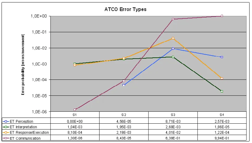
[image:24.612.114.497.293.527.2]Figure 8: ATCO’s Error Types.
The simulator is built in such a way that the probability figures of different error types depend on both the calibration of each Decision Block within the cognitive flowchart and the frequency with which the specific error type can occur within the task analysis as well. Although, in general, the communication is very important in any task performed by ATCOs, Figure 8 shows how much this is true for the use case selected. For the scenario S2 the probability of errors in communication is low because the probability of correct recovery by clarification is very high.
The probability of having an interpretation error is almost invariable trough the scenarios because the handle of aircraft landing procedure does not comprise any relevant diagnostic or planning process. In general, the error types observed in the worst scenario focalize the attention on communication problems; indeed the errors in communication prevail if compared with the other error types that have a probability of occurrence of two orders of magnitude less. Looking at the scenarios S2 and S3 it is possible to observe that a wider spectrum of error types might occur, arguing that intermediate situations are more difficult to manage – thus to improve – than the boundary situations; indeed, if the aim is to work at the Contextual Conditions of scenario S4 and to focalise the effort to improve the communication process, it would be sure huge vantages in safety are reached, i.e. a high rate of reduction of the task failure probability. It is not exactly the same for scenarios S2 and S3.
6. Conclusions and potential developments of the approach
The main evidences on the value of the proposed approach can be summarised as follows:
- the completion of a pilot application shows that PROCOS provides a stochastic model with statistically consistent results based on a large number of simulation samples taking into account the cognitive-related dependency among estimated probabilities and any dependency among different error types or error modes; - the method is able to provide probability values also for correct task and, more
important, for the corrective actions in the recovery phase;
- the use of a specific flowchart for the communication process assures an effective way to model the liveware-livewere interactions able to capture main aspects and criticalities;
- the method used for developing the task analysis (based on flow charts) is able to go beyond the more static fault tree/event tree modelling and yet it provided results able to be included into a more classical Probabilistic Safety Assessment Framework (that may make use of Fault Trees and Event Trees);
- a good integration has been reached and valuable synergies have been demonstrated among ConOps model of ATM, HERA retrospective and PROCOS approach to HRA, in particular referring to the way of modelling both the task and the context, and the calibration process based on HERA dataset.
The approach could be adapted to other fields of study with little efforts (e.g. process industry, nuclear, railway). The main elements that need to be considered are:
- the compatibility of the taxonomy used within the simulator and the one used for collecting accident data;
- the availability of suitable information about the contextual conditions in the retrospective data;
- the development of a task analysis for the new case study down to a level of detail suitable for interacting with the cognitive model.
Some weaknesses have emerged during the development of this project as well. First of all, it clearly appears that the results of the simulation are strongly affected by the available accident database or reports:
- the mathematical model for the relation among CCs and the error type has been derived from the available data set of HERA, which is still incomplete and relatively small;
- the description of the scenario to be simulated is influenced by the level of detail of CC recording within HERA database. Till now the HERA database classifies the CCs observed in a given accident only on their main category, whereas it would be better and more useful to report the precise description of the CCs identified for each event and not only the main category they belong to;
- the HERA database only reports the presence or not of each CC for a considered accident. Therefore, for the application of this study we only used discrete values (0 or 1). The description of the scenario would be more realistic if the CC influence could assume a real value (ranging from 0 to 1).
performed by ATCO and in description of the new scenario through the use of the CCs (PROCOS is already able to consider the equipment and the interaction between the operator actions and the equipment status).
Acknowledgements
The authors would like to express gratitude to Maurizio Salvestrini and the other members of Malpensa and Linate Control Towers for their support in developing the material necessary for this study.
7. References
Baron, S., Zacharias, G., Muralidharan, R., and Lancraft, R. .(1980) "PROCRU: a model for analyzing fligth crew procedures in approach to landing." CR-152397, NASA. 1980
Cacciabue P.C: (1998) “Modeling and Simulation of Human Behaviour in System Control” Springer & Verlag London
Cacciabue, P. C., Decortis, F., Drozdowicz, B., Masson, M., and Nordvik, J. P. (1992). "COSIMO: A Cognitive Simulation Model of Human Decision Making and Behaviour in
Accident Management of Complex Plants." IEEE Transaction on Systems, Man and Cybernetics, IEEE-SMC, 22(5), 1058-1074.
Chang Y.H.J., Mosleh A. (2007) Cognitive modeling and dynamic probabilistic simulation of operating crew response to complex system accidents: Part 1: Overview of the IDAC Model. Reliability Engineering & System Safety, Volume 92, Issue 8, Pages 997-1013 August 2007.
Edwards, E.(1998) “Introductory Overview” in E.L. Wiener & D.C. Nagel (Eds) Human factors in aviation. San Diego, CA: Academic Press.
Eurocontrol (2005) ATM Operational concept volume 2 Concept of Operation Year 2011 Edition 1 Brussels 03.05.2005. Proposed Released Issue
Gore B.F. 2002 Human Performance Cognitive-Behavioural Modeling: A benefit for
Occupational Safety International Journal of Occupational Safety and Ergonomics (JOSE) 2002 Vol. 8 No3 339-351.
Hollnagel E. (1993) “Human Reliability Analysis Context and Control” Academic Press 1993
Isaac A. Shorrock S., Kirwan B.(2002) Human error in European air traffic management: the HERA project Reliability Engineering and System Safety Volume: 75, Issue: 2, February, 2002, pp. 257-272
Isaac, A., Sträter, O. & Van Damme, D. (2004) A method for predicting Human Error in ATM (HERA Predict). HRS/HSP-002-REP-07. Eurocontrol. Brussels
Mauri C. Owen D., Baranzini D.,(2001) Model of Human Machine Integrated System, AITRAM Deliverable D04.1 WP4, 5th Framework Programme, October 2001
Rasch G.(1980) Probabilistic Model for some Intelligence and Attainment Tests. University of Chicago Press. Chicago
Reason J. (1990) Human error. Cambridge University Press.
Stroeve S.,Blom H., Bakker B.(2006) Safety Risk Safety Risk Impact Analysis of an ATC Runway Incursion Alert System Proceedings of the EUROCONTROL Safety R&D Seminar, Barcelona, Spain, 25-27 October 2006.
Sträter O.(2000) Evaluation of Human Reliability on the basis of Operational Experience. GRS-170 Cologne (Germany) GRS 2000.
Sträter, O. (2005) Cognition and safety - An Integrated Approach to Systems Design and Performance Assessment. Ashgate. Aldershot
Sträter, O. and Kirwan, B. (2002) Differences between Human Reliability Approaches in Nuclear- and Aviation-Safety. IEEE Conference on Human Factors and Power Plants, Arizona, 15.-19. September 2002.
Shu, Y., Futura, K., and Kondo, S. (2002). "Team performance modeling for HRA in Dynamic situations." Reliability Engineering and System Safety, 78, 111-121
Takano, K., Sasou, K., and Yoshimura, S. (1995). "Simulation System for Behaviour of an Operating Group (SYBORG)”.
Trucco P., Leva M.C., Corti G., Gallarati G. (2004) A Probabilistic Cognitive Simulator For HRA Studies. CISAP 1 Conference Proceeding. Palermo 2004.
Trucco P., Leva M.C.(2006) A Probabilistic Cognitive Simulator For HRA Studies (PROCOS) Reliability Engineering & System Safety, Volume 92, Issue 8, August 2007, Pages 1117-1130
Wickens C.(1992) “Engineering Psychology and Human Performance” Second Edition New York; Harper-Collins .