ISSN Online: 1913-3723 ISSN Print: 1913-3715
Fast Acquisition Method of GPS Signal Based on
FFT Cyclic Correlation
Hao Cui, Zhigang Li, Zheng Dou
College of Information and Communication Engineering, Harbin Engineering University, Harbin, China
Abstract
Since the global positioning system began to operate, it has become more and more close to people’s lives, and has been applied to various fields now. In order to track and decode GPS signals, GPS signals need to be captured first. The necessary parameters of the captured GPS signal are immediately trans-mitted to the tracking process, and then the navigation message of the satellite can be obtained by tracking process. In this paper, the basic contents related to the signal structure of GPS system are briefly described. Then, the tradi-tional GPS signal acquisition method based on time domain correlation me-thod is introduced, and the GPS signal acquisition meme-thod based on FFT cyc-lic correlation method is discussed in this paper. By comparing the simulation results, two kinds of GPS signal acquisition methods are compared with the calculation time according to the method of controlling variables. For the two GPS signal acquisition methods, the variation of time delay error with SNR is simulated in this paper.
Keywords
GPS, FFT, Satellite Signal, Acquisition, Circular Correlation
1. Introduction
Using GPS system for positioning and navigation, we need to capture the GPS signal at first. In the GPS receiver, the local generated carrier and spread spec-trum code need to synchronize with the carrier and spread specspec-trum code in the received signal. This synchronization is generally divided into two stages: coarse synchronization and fine synchronization [1]. The acquisition process is to es-timate the Doppler shift and the pseudo code phase of the received signal and initialize the tracking loop with these estimates. There are two kinds of com-monly used GPS signal acquisition methods, sliding correlation method and matched filter capture method [2]. The sliding correlation method takes serial
How to cite this paper: Cui, H., Li, Z.G. and Dou, Z. (2017) Fast Acquisition Me-thod of GPS Signal Based on FFT Cyclic Cor-relation. Int. J. Communications, Network and System Sciences, 10, 246-254.
https://doi.org/10.4236/ijcns.2017.108B026
search in time domain and frequency domain, and makes correlation between 1023 code phases of each frequency. This method is simple, but the search time is too long. Although the matching filter can achieve a certain degree of parallel computing, not affected by the pseudo code cycle, but it will take up a lot of hardware resources [3]. In order to get a balance between search speed and re-sources, this paper uses FFT-based acquisition method, serial search in the time domain and frequency domain are in parallel, so as to improve the acquisition speed and not occupy too much resources.
2. GPS Signal Acquisition Based on Time Domain Correlation
2.1. Implementation Ideas and Processes
The signal of the GPS contains three parts: carrier signals (L1 and L2), spread spectrum sequences (C/A codes, P codes or Y codes) and navigation data (D codes) [4]. The local code is represented as a form of C/A code multiplied by an RF signal. The radio frequency signal RF is a complex number, and the local code is multiplied by the RF code and the C/A code [5]. Assuming that the L1 frequency (1575.42 MHz) is down converted to 21.25 MHz, digitized at a rate of 5 MHz to obtain an output frequency of 1.25 MHz. The frequency range of the capture program is (1250 ± 10) kHz, step 1 kHz, and a total of 21 frequency components. The local code can be expressed as:
2 i
j f t
si s
l =C e π (1)
In the above equation, the subscript s represents the satellite number, Cs is
the C/A code of the satellite S, fi = 1250 − 10, 1250 − 9, ···, 1250 + 10 kHz. The
local signal must also be digitized at a 5 MHz sampling rate to produce 5000 data points.
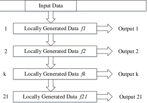
The above 21 sets of data (only corresponding to a satellite C/A code) re- presents 21 frequencies at intervals of 1 kHz. If the C/A code and the frequency of the local signal are correct, and the C/A code phase is aligned, the output is maximized. The flow chart of the acquisition process is as shown in Figure 1:
Input Data
Locally Generated Data f1
Locally Generated Data f2
Locally Generated Data fk
Locally Generated Data f21
1
2
k
21
Output 1
Output 2
Output k
[image:2.595.243.500.536.715.2]Output 21
The operation of the group is as follows: the digitized input signal and the lo-cally generated signal are multiplied by a point (5000 points in total). The square of the product is added to the square of the imaginary part and the square root is the magnitude of the output frequency. Every 200 ns carries on the above opera-tion to the data, after the input data shift 5000 points, has completed the search to the 1ms data, altogether outputs 5000 magnitude values. 21 groups of local signals output 105,000 (5000 × 21) amplitude values. In these amplitude values, the maximum frequency component beyond the threshold corresponds to the Doppler frequency. The maximum value corresponding to the data shift K is the starting position of the C/A code [6].
2.2. Simulation Results and Analysis
When the starting position of the C/A code of the GPS signal is 1234 and the carrier frequency is 1,255,123 Hz, setting the signal-to-noise ratio to −10 dB, the simulation results of the acquisition of the No. 1 satellite signal are shown in Figures 2-4 :
Figure 2. The starting point of the C/A code of the No. 1 satellite.
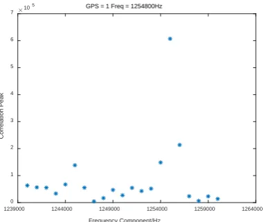
Figure 3. The frequency component of the spread signal of No. 1 satellite.
0 500 1000 1500 2000 2500 3000 3500 4000 4500 5000
Starting Position 0
1 2 3 4 5 6 7
Correlation Peak
105 GPS = 1 max at 1234
1239000 1244000 1249000 1254000 1259000 1264000
Frequency Component/Hz
0 1 2 3 4 5 6 7
Correlation Peak
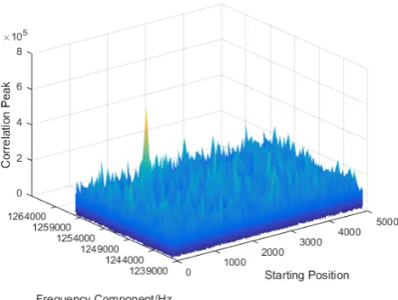
[image:3.595.276.467.542.702.2]Figure 4. The relationship between doppler shift step unit and correlation peak of No. 1 satellite.
This chapter briefly introduces the basic principle and implementation of GPS signal acquisition based on time domain correlation method. Through the si-mulation results, we can see that this method can realize GPS signal acquisition under certain SNR conditions. However, from the principle and the actual si-mulation we can see that the method has a lot of shortcomings in the calculation time, because it is in the time domain point-by-point correlation, the calculation is larger. Therefore, it is necessary to propose a faster GPS signal acquisition method, that is, the following GPS signal acquisition method based on FFT cyc-lic correlation.
3. GPS Signal Acquisition Based on FFT Cyclic Correlation
3.1. Implementation Ideas and Processes
The cyclic correlation DFT of the two sequences is equal to the conjugate of one of the sequences DFT multiplied by another sequence DFT [7]. The cyclic corre-lation method can be used for acquisition, and the computation time can be ef-fectively reduced by fast Fourier transform. The specific steps are as follows:
1) FFT operation is performed on the input data x(n) of 1 ms to obtain X(k). n = k = 0, 1, 2, ···, 4999.
2) Take X(k) complex conjugate, get X(k)*.
3) Generate 21 local codes lsi(n), where i = 1, 2, ···, 21. 4) Take FFT for lsi(n) and get Lsi(k).
5) X(k)* and Lsi(k) are multiplied by point to obtain Rsi(k).
6) Take Rsi(k) inverse FFT transform, get the time domain signal rsi(n), take the absolute value, get |rsi(n)|. A total of 105,000 |rsi(n)|.
7) Give the starting position of the C/A code at a resolution of 200 ns and the carrier frequency at a frequency resolution of 1 kHz at the nth position and the maximum value of the ith frequency |rsi(n)|.
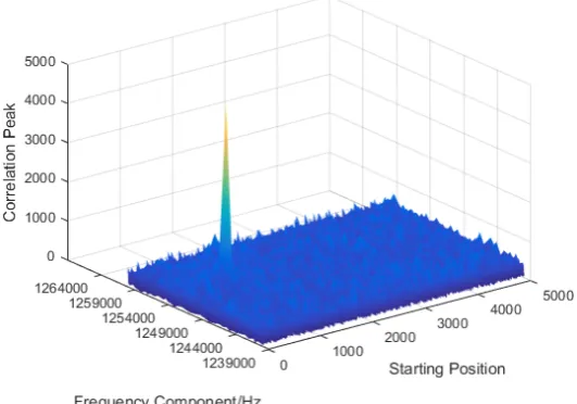
3.2. Simulation Results and Analysis
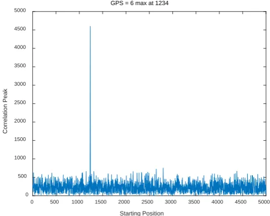
carrier frequency is 1,255,123 Hz, setting the signal-to-noise ratio to −10 dB, the simulation results of the acquisition of the No. 6 satellite signal are shown in Figures 5-7.
[image:5.595.236.503.236.450.2]This chapter gives the GPS acquisition method based on FFT cyclic correla-tion, introduces its basic principle and implementation process, and then gives the simulation results. In the code phase, the fast acquisition algorithm based on FFT requires only one FFT and one IFFT operation to determine the correlation value for all samples in a cycle of C/A codes. Rather than the serial search acqui-sition method, the code phase is gradually sliding to find the correlation value. And it greatly reduces the amount of calculation.
[image:5.595.237.501.488.703.2]Figure 5. The starting point of the C/A code of the No. 6 satellite.
Figure 6. The frequency component of the spread signal of No. 6 satel-lite.
0 500 1000 1500 2000 2500 3000 3500 4000 4500 5000
Starting Position
0 500 1000 1500 2000 2500 3000 3500 4000 4500 5000
Correlation Peak
GPS = 6 max at 1234
1239000 1244000 1249000 1254000 1259000 1264000
Frequency Component/Hz
0 500 1000 1500 2000 2500 3000 3500 4000 4500 5000
Correlation Peak
Figure 7. The relationship between doppler shift step unit and correla-tion peak of No. 6 satellite.
4. Analysis and Comparison of GPS Signal Acquisition
Methods
4.1. Calculating Time
The fast acquisition algorithm based on FFT in the carrier frequency using a di-rect search method, but it requires only once FFT and once IFFT operation in the code phase to determine the correlation value for all samples in a cycle of C/A codes. Rather than the serial search acquisition method, the code phase is gradually sliding to find the correlation value.
Assuming that using a C/A code period of data for acquisition, the sampling points is N. When using the traditional serial search acquisition algorithm, each time of the correlation results need N times multiplication and N-1 times addi-tion. To calculate all the N code phase, a total of N2 need to multiply. Using the fast acquisition algorithm based on FFT, the total amount of computation re-quired is about 2 times the amount of FFT calculation, that is, 2
2 logN N times multiplication, reducing the amount of computation [8].
According to the actual simulation results of MATLAB, the average time of GPS signal acquisition method based on time domain correlation method is 21.124146 seconds, while the average time of GPS signal acquisition method based on FFT cyclic correlation method is only 0.261626 seconds.
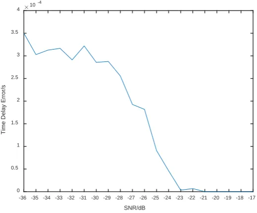
4.2. Time Delay Error
Figure 8. The variation of time delay error with SNR using time domain correlation method.
Figure 9. The variation of time delay error with SNR using FFT method.
As can be seen from Figure 9, the time delay error tends to decrease with the increase of SNR in the given SNR range. In the case of small SNR, because the SNR has a great impact on the GPS signal acquisition results, the results are not stable, and the curve has a floating.
It can be seen from the figure that the results obtained by using the FFT me-thod are similar to those of the time domain correlation meme-thod. The time delay error tends to decrease with the increase of SNR in the given SNR range. In the case of small SNR, because the SNR has a great impact on the GPS signal acqui-sition results, the results are not stable, and the curve has a floating. However, it can be seen that the results obtained using the FFT method are more ideal than
-36 -35 -34 -33 -32 -31 -30 -29 -28 -27 -26 -25 -24 -23 -22 -21 -20 -19 -18 -17
SNR/dB
0.5 1 1.5 2 2.5 3 3.5
Time Delay Error/s
10
-36 -35 -34 -33 -32 -31 -30 -29 -28 -27 -26 -25 -24 -23 -22 -21 -20 -19 -18 -17
SNR/dB
0 0.5 1 1.5 2 2.5 3 3.5 4
Time Delay Error/s
[image:7.595.243.503.334.549.2]the time domain correlation method, and the floating is relatively small.
5. Conclusion
The demand of positioning and navigation has been developing with human ci-vilization, and playing an important role in the development of human history. Not only in defense and military, but also in the civil field it has shown a huge application prospects and broad commercial market, changing everyone’s habits and ways of thinking. In order to track and decode GPS signals, GPS signals need to be captured first. In this paper, the traditional GPS signal acquisition method based on time domain correlation method is introduced, and the GPS signal acquisition method based on FFT cyclic correlation method is discussed. Through the actual simulation and analysis, it is not difficult to conclude that the GPS signal acquisition method based on FFT has more advantages than the traditional time domain correlation method in terms of calculating time and acquisition performance. Therefore, the proposed GPS signal acquisition me-thod based on FFT is a feasible and superior GPS signal acquisition meme-thod.
Acknowledgements
This paper is funded by the International Exchange Program of Harbin Engi-neering University for Innovation-oriented Talents Cultivation, National Natu-ral Science Foundation of China (No. 61401115), National NatuNatu-ral Science Foundation of China (No. 61301095), National Natural Science Foundation of China (No. 61671167), International Science & Technology Cooperation Pro-gram of China (2014 DFR10240), China Postdoctoral Science Foundation (2013- T60346), Harbin Science and Technology Research Projects (P083313026), Nat-ural Science Foundation of Heilongjiang Province (P083014025).
References
[1] Chang, L., Zhang, J., Zhu, Y. and Pan, Q. (2011) Analysis and Optimization of PMF- FFT Acquisition Algorithm for High-Dynamic GPS Signal. IEEE International Con- ference on Cybernetics and Intelligent Systems, Qingdao, 17-19 September 2011, 85- 189. https://doi.org/10.1109/iccis.2011.6070325
[2] Napolitano, A. and Perna, I. (2014) Cyclic Spectral Analysis of the GPS Signal. Digi-tal Signal Processing, 33, 13-33. https://doi.org/10.1016/j.dsp.2014.06.003
[3] Van Nee, D.J.R. and Coenen, A.J.R.M. (1991) New Fast GPS Code-Acquisition Technique Using FFT. Electronics Letters, 27, 158-160.
https://doi.org/10.1049/el:19910102
[4] Ahamed, S.F., Laveti, G., Goswami, R. and Rao, G.S. (2016) Fast Acquisition of GPS Signal Using Radix-2 and Radix-4 FFT Algorithms. IEEE International Conference on Advanced Computing,Bhimavaram,27-28 February 2016, 674-678.
https://doi.org/10.1109/iacc.2016.130
[5] Patel, V. and Shukla, P. (2011) Faster Methods for GPS Signal Acquisition in Fre-quency Domain. International Conference on Emerging Trends in Networks and Computer Communications, 84-88.
[7] Xi, C., Rui, Z. and Tao, S. (2011) A New Rapid Acquisition Algorithm Based on FFT for GPS Signals. Journal of Astronautics, 32, 162-166.
[8] Chen, L. and Meng, W.X. (2011) Design and Implementation for GPS Signal Acqui-sition in Frequency Domain Based on FPGA. Applied Science and Technology, 38, 22-26.
Submit or recommend next manuscript to SCIRP and we will provide best service for you:
Accepting pre-submission inquiries through Email, Facebook, LinkedIn, Twitter, etc. A wide selection of journals (inclusive of 9 subjects, more than 200 journals)
Providing 24-hour high-quality service User-friendly online submission system Fair and swift peer-review system
Efficient typesetting and proofreading procedure
Display of the result of downloads and visits, as well as the number of cited articles Maximum dissemination of your research work
Submit your manuscript at: http://papersubmission.scirp.org/