http://www.scirp.org/journal/cs ISSN Online: 2153-1293 ISSN Print: 2153-1285
DOI: 10.4236/cs.2017.88014 Aug. 28, 2017 202 Circuits and Systems
Fuzzy Logic Controller Implementation of
Power Quality Improvement Using UPQC
S. Balaslubramaniyan1, T. S. Sivakumaran2
1Department of EEE, Mailam Engineering College, Mailam, India
2Department of EEE, Arunai College of Engineering, Tiruvannamalai, India
Abstract
This paper presents a gross examination about Unified Power Quality Condi-tioner (UPQC) to invigorate the power issues at the distribution level of the electrical system. Nowadays power electronics research has added the impor-tance of power quality studies, for concrete illustration, Custom Power Devic-es (CPD) and Flexible AC Transmission position (FACTS) devicDevic-es. The ap-proach offered in this paper utilizes the series and shunt compensator of Uni-fied Power Quality Conditioner (UPQC) to inject a compensation voltage in- phase with the source current over voltage fluctuations. The execution of two structures of UPQC, left-shunt (L-UPQC) and right-shunt (R-UPQC) are in-vestigated under diverse operating conditions based on the fuzzy logic con-troller to raise the value of power quality of a single feeder distribution system by MATLAB/Simulink programming. Various power quality issues have been analyzed in this study. Finally, the right shunt UPQC is outperformed in this proposed power system.
Keywords
Left Shunt UPQC, Right Shunt UPQC, Fuzzy Logic Controller, Power Quality
1. Introduction
Power quality issues are getting increasingly massive in nowadays in the break of the expanding number of power electronic devices that hold on as nonlinear loads. A generous assorted status of answers for power quality issues is notice-able for distribution network operator and the end user [1]. The power handling at the source, load and for reactive and harmonic compensation by power elec-tronic devices are getting preferably prevalent due to the vast advantages offered by them. The shunt active power filter (APF) is consistently associated with the
How to cite this paper: Balaslubrama-niyan, S. and Sivakumaran, T.S. (2017) Fuzzy Logic Controller Implementation of Power Quality Improvement Using UPQC.
Circuits and Systems, 8, 202-226.
https://doi.org/10.4236/cs.2017.88014
Received: May 6, 2016 Accepted: May 13, 2016 Published: August 28, 2017
Copyright © 2017 by authors and Scientific Research Publishing Inc. This work is licensed under the Creative Commons Attribution International License (CC BY 4.0).
http://creativecommons.org/licenses/by/4.0/
DOI: 10.4236/cs.2017.88014 203 Circuits and Systems loads to compensate for all told current related issues, for example, the reactive power compensation, power factor improvement, current harmonic compensa-tion, and load unbalance compensacompensa-tion, whereas the series active power filter is installed in a series mutually a line through the series transformer. It acts as con-trolled voltage source and can reimburse all voltages associated glitches, for ex-ample voltage sag, voltage harmonics, voltage swell, flicker, etc. [2]. UPQC is a Custom Power Device and consists of arm in arm series active power filter that reimburses voltage unbalances, voltage harmonics, voltage sag/swell, voltage flicker and shunt active power filter that compensates current harmonics, cur-rent unbalance and reactive curcur-rent [3].
UPQC is well known as the universal active power line conditioner, universal power quality conditioning system, and universal active filter [4] [5]. UPQC system can be cut apart into two sections: The control unit and the power cir-cuit. The control unit includes disruption detection, reference signal generation, the gate signal generation and voltage/current measurements. Power circuit contains of two voltage source converters, standby and system protection sys-tem, harmonic filters and injection transformers. Power electronic based appli-ance, such as Flexible AC Transmission Systems (FACTS), High-Voltage DC (HVDC), and Custom Power technologies comprise some of the closely prom-ising technical advancements to address the new operational challenges being presented today. These advancements are based on the high-performance capac-ity of the power electronic appliance to accept rapidly to system events, grow power transfer limits, and invigorate the quality of power delivered.
With respect to the Custom Power necessities [6], utility distribution net-works, sensitive industrial loads, and critical commercial operations can possibly experience the ill effects from various types of outages and service interruptions. These can cost significant financial losses per incident based on occurrence downtime, lost production, inactive workforces, and other measurable and non- measurable factors. The sorts of interruptions experienced are named power quality issues and are frequently brought on by voltage sags and swells, lightning strikes, and other distribution system related disturbances. In numerous cases, the utilization of Custom Power equipment, for example, Dynamic Voltage Re-storers (DVR), Solid-State Transfer Switches (SSTS), or Distribution level Static Compensators (D-STATCOM), can be probably the most practical answers for moderate these sorts of power quality issues. There have been various uses of Custom Power technologies [7]-[13].
DOI: 10.4236/cs.2017.88014 204 Circuits and Systems compensator (USSC) went for inspecting its ability in enhancing power quality in a power distribution system. The USSC simulation model includes 12-pulse inverters, which are associated in arrangement and shunt to the system. A gen-eralized sinusoidal pulse width modulation switching technique is created by Hannan [16]. This mix permits a simultaneous compensation for source side currents and delivered voltage to the load.
In this way, the operation of the UPQC secludes the utility from current qual-ity issues of load and in the meantime isolates the load from the voltage qualqual-ity problems of utility.
The point of this work to present the power quality issues and to discuss the solutions of some of these problems is using power electronic controllers. The paper examines the power quality problems with UPQC with the execution of the left shunt and right shunt connection of the proposed power system fuzzy logic controller approach.
2. Unified Power Quality Conditioner (UPQC)
The general diagram of an UPQC distribution network is shown in Figure 1. An UPQC combines an arrangement of a series and a shunt compensator together. The supply voltage is sinusoidal for unbalanced and nonlinear loads. The UPQC can likewise make the current drawn from the supply (is) in phase with the
ter-minal voltage (vt). Therefore, the voltage of any bus upstream from the PCC will
not be pretentious due to a nonlinear and unbalanced load. Though, it will be problematic to rectify the unbalance and distortion created by the source voltage using this device. In this manner, the upstream bus voltages will remain unbal-anced and distorted [17].
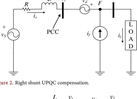
The single-line diagrams of these two systems are shown in Figure 2 and Fig-ure 3. In these figFig-ures, the voltage at the PCC is concerned to as the terminal voltage vt. The load voltage, load current, and source current are indicated by vl,
il and is respectively. Vd indicates the voltage and current injected by the UPQC
and if respectively. The source voltage is indicated by vs, while R and L constitute
the feeder impedance.
The UPQC shall perform the following two functions, one is to change the feeder (source) current is to adjust sinusoids through the shunt compensator and the second is to change the load voltage (vl) to balanced sinusoids through
the series compensator besides control it to the desired value. Contingent upon the location of the shunt compensator on series compensator, the UPQC model
UPQC
v
sFeeder
i
sv
tv
li
lLoad
DOI: 10.4236/cs.2017.88014 205 Circuits and Systems
vd
L O A D +
R L vt + F
il if
PCC
vl
is
[image:4.595.255.489.78.247.2]vS
Figure 2. Right shunt UPQC compensation.
v
dL
O
A
D
+
R
L
v
tF
+
i
li
fPCC
v
li
s [image:4.595.252.493.145.385.2]v
SFigure 3. Left shunt UPQC compensation.
could be named as Right Shunt-UPQC or Left Shunt-UPQC. Both topologies of UPQC have similar features. The primary motivation behind UPQC and other similar custom power controllers is to detect voltage and current imperfections and after that give compensation or disconnection of custom power controllers from the distribution system.
2.1. Left Shunt UPQC Configuration
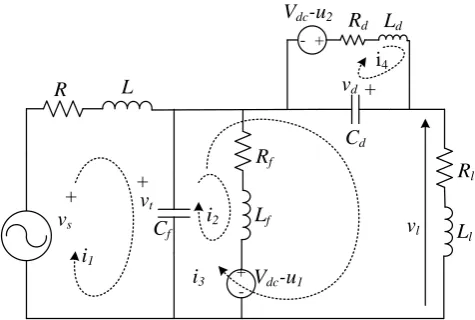
The left-shunt UPQC schematic is appeared in Figure 4. In this structure, a ca-pacitor filter utilized for both series and the shunt inverters. The following issue won’t emerge in the left shunt UPQC regardless of the possibility that we utilize capacitor filters with both shunt and series inverters. The equivalent circuit of the left shunt UPQC is appeared in Figure 5. For this situation, the shunt in-verter tracks the terminal voltage Vt, and the series inverter keeps up the voltage
over the load Vl by following the voltage Vd. Hence, the two inverters track two
quantities regardless of the possibility that they are independent. It is hence ex-pected that the stability issue won’t emerge for left-shunt UPQC structure.
Figure 5 demonstrates the single-phase equivalent circuit of the left shunt UPQC, the leakage inductance of the series transformer is signified by Ld. The
DOI: 10.4236/cs.2017.88014 206 Circuits and Systems
Figure 4. Left shunt UPQC configuration.
Ld Ll Cd - + L Lf - + R vs
+ +vt
i3 i2
i1
Rf
Vdc-u1
vl Rl vd+
Rd Vdc-u2
Cf
i4
Figure 5. The equivalent circuit of Left shunt UPQC.
can likewise be composed with six state variables and two input variables. The state and input vectors are
T
1 2 3 4 t d
x = i i i i v v , T
1 2
c c
u = u u . (1)
Moreover, the state space equation of the system is then given by,
1 2 s
x=Ax+B u+B v .
where
1
0 0 0 0
1
0 0 0 0
1 1
0 0 0
1
0 0 0 0
1 1 1
0 0 0
1 1
0 0 0 0
f
f f
l
l l l
d
d d
f f f
d d R L L R L L R
L L L
A
R
L L
C C C
[image:5.595.253.491.242.402.2]DOI: 10.4236/cs.2017.88014 207 Circuits and Systems 1
0 0
0
0 0
0
0 0
0 0
dc
f
dc
d V
L
B
V
L
−
=
(3)
2 1
0 0 0 0 0 L
B
=
(4)
2.2. Right Shunt UPQC Configuration
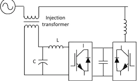
The schematic diagram of the right shunt structure appears in Figure 6. With the right shunt UPQC structure, the outputs of the VSIs realizing the shunt compensator are directly associated with three single-phase transformers. The phase sides of the secondary terminals are associated in shunt with the distribu-tion feeder. Three filter capacitors, one for every phase, are likewise associated in shunt to give ways to the switching frequency harmonics created by the three VSIs. Three LC filters are attached to the three output terminals of the three VSIs realizing the series compensator. The secondary terminals of the three sin-gle-phase transformers are then associated with infuse voltages in series with the distribution feeder. The LC filters are utilized to bypass the switching frequency harmonics.
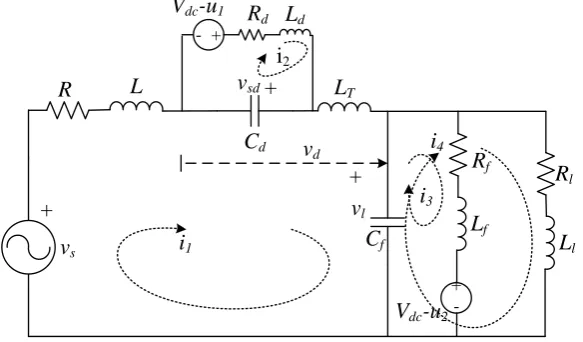
The single-phase equivalent circuit of the right shunt UPQC is appeared in Figure 7. In this figure R and L indicate the feeder parameters. Rl and Ll mean
the load. The LC filter over the series inverter is spoken to by Ld and Cd while the
[image:6.595.324.541.68.302.2]resistance Rd speaks to the inverter losses. The inductance LT signifies the leakage
Figure 6. Right shunt UPQC configuration.
Injection transformer
L
C
[image:6.595.262.488.574.706.2]DOI: 10.4236/cs.2017.88014 208 Circuits and Systems
Ld
Ll
Cd
- + L
Lf - +
R
vs
+
+ vl
i3
i4
i1
Rf
Vdc-u2
vd
Rl
vsd+
Rd
Vdc-u1
Cf
i2
[image:7.595.228.520.76.247.2]LT
Figure 7. The equivalent circuits of right shunt UPQC.
inductance of the transformers associated with the series. The leakage induc-tance of the shunt transformer is indicated by Lf while the resistance Rf speaks to
losses. The shunt filter capacitor is meant by Cf, the voltage at the load terminal
is the voltage over this filter capacitor. The series injected voltage Vd is appeared
in Figure 7 while the voltage Vsd is the voltage over the capacitor Cd. A typical
capacitor supplies the series and shunt inverters. Vdc signifies the voltage across
this capacitor. The switched voltages over the series and shunt inverter yield terminals are then meant by Vdcu1 and Vdcu2 respectively.
From right-shunt UPQC structure, the tracking control, stability issue is stay-ing away from through the choice of LC filter for the series inverter and capaci-tor filter for the shunt inverter. Consider the equivalent circuit; the inductance LT will be zero as the transformer leakage inductance will then be in series with
the series inverter. However, a feedback control is required to track the voltages crosswise over both the capacitors and the absence of LT tracking voltage Vl by
the shunt compensator will make the tracking voltage Vd over the series
com-pensator repetitive and vice versa.
By driving the two inverters to track the voltages over their respective capaci-tors, the stability issue will emerge as one controller will meddle with the track-ing execution of the other. Hence, to maintain a strategic distance from the tracking issue the LC filter structure for the series inverter is more appropriate for the right shunt UPQC. Likewise, the LC filter limits the switching frequency harmonics in the primary of the transformer associated with it.
To infer a state-space model of the system, that the circuit of contains six state variables - four loop currents and two capacitor voltages. It can be,
T
1 2 3 4 sd l
x = i i i i v v. (5)
The circuit of Figure 7 additionally contains three functions the voltage source v and switching variables u1 and u2. Give us a chance to supplant u1 and
u2 by the continuous time variables uc1 and uc2 individually and characterize the
DOI: 10.4236/cs.2017.88014 209 Circuits and Systems
T
1 2
c c
u = u u . (6)
The state space equation of the framework is then given by
1 2 s
x=Ax+B u+B v . (7)
where the A, B1 and B2 are given by
1 1
0 0 0
1
0 0 0 0
1
0 0 0 0
1
0 0 0 0
1 1
0 0 0 0
1 1 1
0 0 0
r r r
d d d f f f l l l d d
f f f
R
L L L L L L
R L L R L L A R L L C C
C C C
− − + + + − − − = − − − −
. (8)
0 0 0 0 0 0 0 0 0 0 dc d dc f t V L V L B − =
. (9)
2 1 0 0 0 0 0 T L L B + =
DOI: 10.4236/cs.2017.88014 210 Circuits and Systems
3. Fuzzy Logic Controller
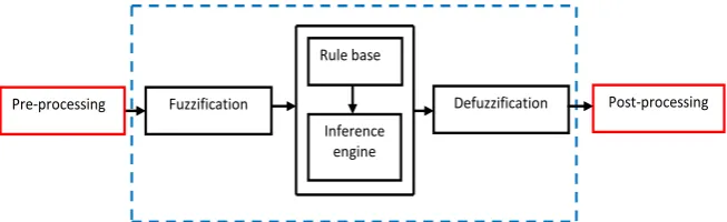
The fuzzy control gives a formal technique to speaking to, controlling, and ex-ecuting a human’s heuristic information about how to control a framework. Fuzzy memberships NL, NM, NS, ZE, PS, PM, PL is characterized as negative large, negative medium, negative small, zero, positive small, positive medium and positive significant. Figure 8 demonstrates the fundamental structure of a fuzzy logic controller.
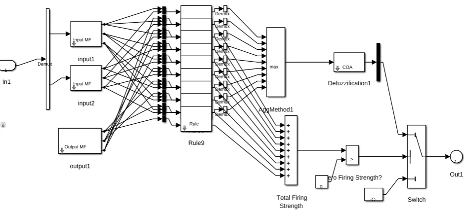
[image:9.595.210.537.345.445.2]The “fuzzy inference system” is a popular computing framework based on the ideas of fuzzy set theory, fuzzy if-then rules, and fuzzy reasoning [18]. It has found successful applications in a wide variety of fields, such as automatic con-trol, data classification, decision analysis, expert systems, time series prediction, robotics, and pattern recognition [19]. Because of its multidisciplinary nature, the fuzzy inference system is known by various different names, such as “fuzzy expert system” [20], “fuzzy model” [21], “fuzzy associative memory” [22], and essentially “fuzzy system”. Proposed fuzzy rule base surface perspective of UPQC system is appeared in Figure 9. Figure 10 demonstrates the internal ar-chitecture of the proposed fuzzy logic controller of UPQC system.
Figure 8. The fuzzy logic controller—basic structure representation.
Figure 9. Prospective of rule base surface for UPQC system with fuzzy controller.
Pre-processing Fuzzification Defuzzification Post-processing Rule base
[image:9.595.212.538.479.705.2]DOI: 10.4236/cs.2017.88014 211 Circuits and Systems
Figure 10. Fuzzy controller (internal structure) configuration of the proposed UPQC system.
4. Simulation and Discussion of Proposed UPQC System
Figure 11 demonstrate the structure of the proposed UPQC system simulated using MATLAB, Simulink; A three phase 440 V, 50 Hz, three wire power system is considered for this work. The main motivation behind an UPQC is to com-pensate for supply voltage power quality issues, such as sags, swells, unbalance, flicker, harmonics, and for load current power quality issues, such as harmonics, unbalance reactive current, and neutral current. Two inverters, one related ath-wart the load which acts as a shunt APF and further related in series with the line as that of series APF. The Shunt coupling inductor Lsh is utilized to interfacethe shunt inverter to the system. It also helps in smoothing the current wave shape. Sometimes an isolation transformer is used to electrically isolate the in-verter from the system. A typical dc link can be framed by using a capacitor or an inductor. In Figure 11, the dc link is realized using a capacitor which interre-lates the two inverters and similarly keeps a continuous self-supporting dc bus voltage across it. A filter that serves as a passive low-pass filter (LPF) and serves to eliminate high-frequency switching ripples on generated inverter output vol-tage. Series injection transformer utilized to interface the series inverter in the system. A suitable turn ratio is often considered to decrease the current or vol-tage rating of the series inverter. In principle, UPQC is an integration of shunt and series APFs with a typical self-supporting dc bus. The shunt inverter in UPQC is controlled in a current control mode such that it offers a current which is equivalent to the set value of the reference current as signified by the UPQC control algorithm. Also, the shunt inverter plays a main part in attaining re-quired performance from an UPQC system by maintaining the dc bus voltage at a set reference value to eliminate the harmonics generated by a nonlinear load.
This circuit is operated under two operating modes, one is Left shunt asso-ciated UPQC, and another is right shunt assoasso-ciated UPQC. During left shunt
1 Out1 1
In1
Demux
Input MF
input1
Input MF
input2
Output MF
output1
max
AggMethod1
Total Firing Strength Rule
Rule1 Demux
Rule
Rule2 Demux
Rule
Rule3 Demux
Rule
Rule4 Demux
Rule
Rule5 Demux
Rule
Rule6 Demux
Rule
Rule7 Demux
Rule
Rule8 Demux
Rule
Rule9 Demux
COA
Defuzzification1
>
Zero Firing Strength? 0
DOI: 10.4236/cs.2017.88014 212 Circuits and Systems
Figure 11. UPQC connected power system configuration with Simulink model structure.
UPQC, the shunt converter is attached to the load side, and the series converter is associated with source side through series injection transformer. Similarly, the right shunt associated system; the converter association is turned around. The proposed UPQC system compensates the load voltage on the source voltage as-sociated with series converter. The control groupings of left and right shunt compensation of UPQC system are done through the series and shunt regulator by providing legitimate gate pulse generation to the UPQC.
4.1. Left Shunt UPQC System
DOI: 10.4236/cs.2017.88014 213 Circuits and Systems
Figure 12. Voltage waveform of proposed power system before compensation with simulated source voltage.
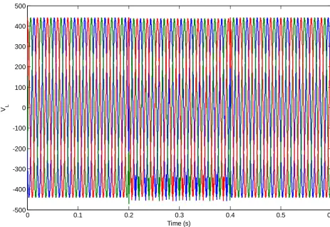
Figure 13. Load voltage waveform simulated output after compensated by left shunt UPQC.
0 0.1 0.2 0.3 0.4 0.5 0.6
-500 -400 -300 -200 -100 0 100 200 300 400 500
Time (s)
V in
0 0.1 0.2 0.3 0.4 0.5 0.6
-500 -400 -300 -200 -100 0 100 200 300 400 500
[image:12.595.62.526.385.703.2]DOI: 10.4236/cs.2017.88014 214 Circuits and Systems
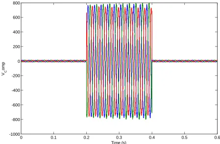
Figure 14. The simulated output of compensation voltage waveform injected by left shunt UPQC.
Figure 15. Output of the load current waveform after compensated by left shunt UPQC.
0 0.1 0.2 0.3 0.4 0.5 0.6
-1000 -800 -600 -400 -200 0 200 400 600 800
Time (s) V C
o
m
p
0 0.1 0.2 0.3 0.4 0.5 0.6
-0.08 -0.06 -0.04 -0.02 0 0.02 0.04 0.06 0.08
Time (s) I o
(A
[image:13.595.92.536.399.705.2]DOI: 10.4236/cs.2017.88014 215 Circuits and Systems
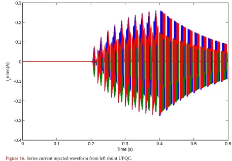
[image:14.595.92.540.362.704.2]Figure 16. Series current injected waveform from left shunt UPQC.
Figure 17. Generated shunt voltage waveform from left shunt UPQC.
0 0.1 0.2 0.3 0.4 0.5 0.6
-0.4 -0.3 -0.2 -0.1 0 0.1 0.2 0.3
Time (s) I s
e
ri
e
s
(A
)
0 0.1 0.2 0.3 0.4 0.5 0.6
-50 -40 -30 -20 -10 0 10 20 30 40 50
Time (s) V s
DOI: 10.4236/cs.2017.88014 216 Circuits and Systems
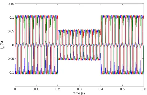
Figure 18. Source voltage waveforms of right shunt UPQC before compensation.
Figure 19. Source current waveforms of right shunt UPQC before compensation.
0 0.1 0.2 0.3 0.4 0.5 0.6
-500 -400 -300 -200 -100 0 100 200 300 400 500
Time (s)
V in
0 0.1 0.2 0.3 0.4 0.5 0.6
-0.1 -0.05 0 0.05 0.1 0.15
Time (s)
I in
(A
[image:15.595.61.538.395.705.2]DOI: 10.4236/cs.2017.88014 217 Circuits and Systems
Figure 20. Load voltage waveform after compensation of right shunt UPQC.
Figure 21 demonstrates the load current waveform of right shunt UPQC with right shunt UPQC compensation. Figure 22 demonstrates the compensation voltage waveform injected from right shunt UPQC to compensate the load vol-tage of the power system. Figure 23 speaks to the series current, Shunt volvol-tage and DC link reaction of right shunt UPQC.
4.2. Right Shunt UPQC System
Figure 24 demonstrated the uncompensated and compensated (left shunt and Right shunt) reaction of source current waveform and Figure 25 demonstrated the uncompensated and compensated (left shunt and Right shunt) reaction of the load current waveform. From Figure 24, Figure 25, obviously the wave-forms are exceptionally smooth with the nearness of UPQC. The UPQC has compensated the harmonic segment present in the system. Also, obviously the right shunt UPQC waveform is exceptionally smooth compared with left shunt UPQC performance. UPQC compensation voltage and current reactions are ex-hibited in Figure 26, Figure 27. Figure 26 demonstrates the shunt segment in-jected voltage reaction of UPQC and Figure 27 demonstrates the series compo-nent injected current reactions of the system. Figures 28-30 demonstrated the real and reactive power reactions of uncompensated and compensated (left shunt and right shunt) using UPQC system. Reactive power observation from Figure 29, Figure 30 indicates that lagging compensation in left shunt configu-ration and leading compensation in right shunt configuconfigu-ration of the UPQC
0 0.1 0.2 0.3 0.4 0.5 0.6
-500 -400 -300 -200 -100 0 100 200 300 400 500
Time (s)
DOI: 10.4236/cs.2017.88014 218 Circuits and Systems
Figure 21. Load current waveform of right shunt UPQC connected power system.
Figure 22. Compensation voltage waveform injected from right shunt UPQC.
0 0.1 0.2 0.3 0.4 0.5 0.6
-0.08 -0.06 -0.04 -0.02 0 0.02 0.04 0.06 0.08
Time (s)
i 0
(A
)
0 0.1 0.2 0.3 0.4 0.5 0.6
-500 -400 -300 -200 -100 0 100 200 300 400 500
Time (s)
V c
o
mp
(V
[image:17.595.62.536.395.702.2]DOI: 10.4236/cs.2017.88014 219 Circuits and Systems
Figure 23. Series current, Shunt voltage and DC link response of right shunt UPQC.
Figure 24. Source side current response of the system without and with UPQC system.
0.4 0.42 0.44 0.46 0.48 0.5 0.52 0.54 0.56 0.58 0.6
V shunt
(V)
-200 0 200
0.4 0.42 0.44 0.46 0.48 0.5 0.52 0.54 0.56 0.58 0.6
I series
(A)
-1 0 1
Time in sec
0.4 0.42 0.44 0.46 0.48 0.5 0.52 0.54 0.56 0.58 0.6
V
DC
0 50 100 150
0.2 0.21 0.22 0.23 0.24 0.25 0.26 0.27 0.28 0.29 0.3
-4 -2 0 2 4
IA
0.2 0.21 0.22 0.23 0.24 0.25 0.26 0.27 0.28 0.29 0.3
-4 -2 0 2 4
IB
0.2 0.21 0.22 0.23 0.24 0.25 0.26 0.27 0.28 0.29 0.3
-4 -2 0 2 4
IC
Time in sec
[image:18.595.210.536.399.700.2]DOI: 10.4236/cs.2017.88014 220 Circuits and Systems
Figure 25. Load side current response of the system without and with UPQC system.
Figure 26. Injected voltage response of Shun connected UPQC.
0.2 0.205 0.21 0.215 0.22
-0.1 -0.05 0 0.05 0.1
IA
0.2 0.205 0.21 0.215 0.22
-0.1 -0.05 0 0.05 0.1
IB
0.2 0.205 0.21 0.215 0.22
-0.1 -0.05 0 0.05 0.1
IC
Time in sec
without UPQC with UPQC (Left Shunt) with UPQC (Right Shunt)
0.4 0.42 0.44 0.46 0.48 0.5 0.52 0.54 0.56 0.58 0.6
-100 -50 0 50 100
VA
0.4 0.42 0.44 0.46 0.48 0.5 0.52 0.54 0.56 0.58 0.6
-100 -50 0 50 100
VB
0.4 0.42 0.44 0.46 0.48 0.5 0.52 0.54 0.56 0.58 0.6
-100 -50 0 50 100
DOI: 10.4236/cs.2017.88014 221 Circuits and Systems
Figure 27. Injected current response of series converter.
Figure 28. Real and reactive power response for without UPQC.
0.4 0.42 0.44 0.46 0.48 0.5 0.52 0.54 0.56 0.58 0.6
-0.5 0 0.5
IA
0.4 0.42 0.44 0.46 0.48 0.5 0.52 0.54 0.56 0.58 0.6
-0.5 0 0.5
IB
0.4 0.42 0.44 0.46 0.48 0.5 0.52 0.54 0.56 0.58 0.6
-0.5 0 0.5
Time in sec IC
0 0.02 0.04 0.06 0.08 0.1 0.12 0.14 0.16 0.18 0.2
0 0.2 0.4 0.6 0.8 1
R
eal
p
o
w
er
0 0.02 0.04 0.06 0.08 0.1 0.12 0.14 0.16 0.18 0.2
0 0.2 0.4 0.6 0.8 1
Time in sec
R
eact
iv
e P
o
w
DOI: 10.4236/cs.2017.88014 222 Circuits and Systems
Figure 29. Real and reactive power responses for with right shunt UPQC.
Figure 30. Real and reactive power response for with left shunt UPQC.
0 0.02 0.04 0.06 0.08 0.1 0.12 0.14 0.16 0.18 0.2
-5 0 5 10 15
R
eal
P
o
w
er
0 0.02 0.04 0.06 0.08 0.1 0.12 0.14 0.16 0.18 0.2
-8 -6 -4 -2 0 2
Time in sec
R
eac
ti
v
e pow
er
0 0.02 0.04 0.06 0.08 0.1 0.12 0.14 0.16 0.18 0.2
0 2 4 6 8 10 12
R
eal
p
o
w
er
0 0.02 0.04 0.06 0.08 0.1 0.12 0.14 0.16 0.18 0.2
0 2 4 6 8 10
Time in sec
R
eac
ti
v
e P
ow
DOI: 10.4236/cs.2017.88014 223 Circuits and Systems
%THD (Harmonic order) %THD (Frequency order)
[image:22.595.56.541.62.705.2]without UPQC With L Shunt With R Shunt
Figure 31. Harmonic analysis of without and with left shunt and right shunt UPQC system.
0 2 4 6 8 10 12 14 16
0 5 10 15 20 25 30 35 Harmonic order Fundamental (50Hz) = 0.01543 , THD= 45.10%
M ag ( % of F undam ent al )
0 100 200 300 400 500 600 700 800 900 1000
0 5 10 15 20 25 30 35 Frequency (Hz) Fundamental (50Hz) = 0.01543 , THD= 45.10%
M ag ( % of F unda m ent al )
0 2 4 6 8 10 12 14 16 18 20
0 0.1 0.2 0.3 0.4 0.5 0.6 Harmonic order Fundamental (50Hz) = 2.554 , THD= 2.51%
M ag ( % of F undam ent al )
0 100 200 300 400 500 600 700 800 900 1000
0 5 10 15 20
Fundamental (50Hz) = 0.05623 , THD= 29.35%
Frequency (Hz) M ag ( % of F undam ent al )
0 2 4 6 8 10 12 14 16 18 20
0 0.1 0.2 0.3 0.4 0.5 0.6 0.7 0.8 Harmonic order Fundamental (50Hz) = 2.521 , THD= 2.15%
M ag ( % of F undam ent al )
0 100 200 300 400 500 600 700 800 900 1000
0 2 4 6 8 10 12 14 16 18 20 Frequency (Hz) Fundamental (50Hz) = 0.05733 , THD= 26.93%
DOI: 10.4236/cs.2017.88014 224 Circuits and Systems
Table 1. % THD analysis of UPQC system.
System %THD (Harmonic order) %THD (Frequency order)
Without UPQC 45.10 45.10
Left Shunt UPQC 2.51 29.35
Right Shunt UPQC 2.15 26.93
system. Both left shunt and right shunt evacuate the harmonic part introduce into the system.
Harmonic analysis reaction for uncompensated and compensated (left shunt and right shunt) are introduced in Figure 31. From the Figure 31, unmistakably both left shunt and right shunt associated UPQC system has filtered out a large portion of the harmonic segment found in the system still, right shunt is by all accounts better than left shunt, in which shunt component is nearer to the load side instead of source side in left shunt configuration system. Table 1 indi-cates % THD overall harmonic analysis of left and right shunt UPQC system. Table 1 speaks to the overall harmonic analysis of both the left shunt and right shunt associated UPQC system and compared with the conventional system without UPQC. From the comparative performance analysis, the table represents to the right shunt UPQC ends up being better over reactive power compensa-tion.
5. Conclusion
A broad simulation study has been displayed in the paper to demonstrate the presence of the left shunt and right UPQC. The load voltage and current are compensated by the implementation of UPQC in left shunt and right shunt of the power system. Also, the reactive power compensation with the magnificent transient reaction is necessary. From the system point of perspective, the per-formance of the right shunt UPQC and left shunt UPQC applications don’t dif-fer all the more, however the right shunt UPQC is performed superior to any-thing left shunt. In any case, if 100% terminal voltage compensation has to be given from the UPQC under a voltage sag condition, the right shunt configura-tion of the UPQC is found to be more economical. In this way, the fuzzy control strategy can lessen the rating of the installed UPQC significantly without com-promising on the wanted performance objectives as identified by the network codes. With the implementation of the fuzzy controller, both left, and right shunt UPQC configurations are performed well to expel the harmonics and real and reactive power compensation. Nonetheless, from the overall performance, it is observed that the right shunt UPQC is performed better than left shunt UPQC configuration as appeared in the outcome Table 1.
References
DOI: 10.4236/cs.2017.88014 225 Circuits and Systems
https://doi.org/10.1109/61.660927
[2] Khadkikar, V. and Chandra, A. (2008) A New Control Philosophy for a Unified Power Quality Conditioner (UPQC) to Coordinate Load-Reactive Power Demand between Shunt and Series Inverters. IEEE Transactions on Power Delivery, 23, 2522-2534. https://doi.org/10.1109/TPWRD.2008.921146
[3] Mekri, F., Machmoum, M.A., Mazari, N.A. and Iren, B. (2008) A Fuzzy Hysteresis Voltage and Current Control of a Unified Power Quality Conditioner. 34thAnnual Conference of the IEEE Industrial Electronics Society, 44, 2684-2689.
https://doi.org/10.1109/IECON.2008.4758382
[4] Muoz, J.A., Espinoza, J.R., Rubilar, L.A., Moran, L.A. and Melin, P.E. (2008) A Modular Approach for Integrating Harmonic Cancellation in a Multi-Cell Based UPQC. 34th Annual Conference of the IEEE Industrial Electronics Society, 21, 3178-3183. https://doi.org/10.1109/IECON.2008.4758469
[5] Jacobina, C.B., Santos, W.R.N., Oliveira, A.C., Da Silva, E.R.C. and Dos Santos, E.C. (2007) Single Phase Universal Active Filter without Transformer. IEEE Applied Power Electronics Conference,36, 698-703.
https://doi.org/10.1109/APEX.2007.357591
[6] Hingorani, N.G. (1995) Introducing Custom Power. IEEE Spectrum, 32, 41-48.
https://doi.org/10.1109/6.387140
[7] Takeda, M., Yamamoto, H., Aritsuka, T., Kamiyama, I. and Reed, G.F. (1999) De-velopment of a Novel Hybrid Switch Device and Application to a Solid-State Trans-fer Switch. Proceedings of the IEEE PES Winter Power Meeting,2, 1151-1156. [8] Takeda, M., Murakami, S., Izuka, M., Kishida, Y., Hase, S. and Mochinaga, M.
(1995) Development of SVG Series for Voltage Control over Three-Phase Unbal-ance Caused by Railway Load. International Conference on Power Electronics
(IPEC), 1, 603-609.
[9] Reed, G.F., Takeda, M., Iyoda, I., Murakami, S. and Aritsuka, T.K. (1999) Improved Power Quality Solutions Using Advanced Solid-State Switching and Static Com-pensation Technologies. Proceedings of the IEEE PES Winter Power Meeting, 1, 1132-1137.
[10] Reason, J. (1996) Solid-State Transfer Switch. Electrical World, 1, 56-59.
[11] Schwartzenberg, J.W. and De Doncker, R.W. (1995) 15 kV Medium Voltage Static Transfer Switch. IEEE Industry Application Conference, 3, 2515-1137.
https://doi.org/10.1109/IAS.1995.530623
[12] Woodley, N.J., Morgan, L. and Sundaram, A. (1999) Experience with an Inverter- Based Dynamic Voltage Restorer. IEEE PES Transactions, 14, 1181-1186.
https://doi.org/10.1109/61.772390
[13] Mueller, D. (2012) Guide for Application of Power Electronics for Power Quality Improvement on Distribution Systems Rated 1 kV through 38 kV. IEEE P1409 Dis-tribution Custom Power Task Force, 1, 1409-2012.
[14] Fujita, H. and Akagi, H. (1998) The Unified Power Quality Conditioner: The Inte-gration of Series and Shunt Active Filters. IEEE Transaction on Power Electronics, 13, 315-322. https://doi.org/10.1109/63.662847
[15] Shayanfar, H.A. and Mokhtarpour, A. (2010) Management, Control and Automa-tion of Power Quality Improvement.In: Eberhard, Ed., Power Quality Book, In-Tech, Croatia, 127-152.
DOI: 10.4236/cs.2017.88014 226 Circuits and Systems
Power Delivery, 20, 1650-1656. https://doi.org/10.1109/TPWRD.2004.833875
[17] Sudharshan, R.G. and Vijay, K.K. (2013) Unified Power Quality Conditioner (UPQC) during Voltage Sag and Swell. International Journal of Emerging Trends in Electrical and Electronics, 1, 12-23.
[18] Jang, J. and Gulley. (1997) MATLAB: Fuzzy Logic Toolbox User’s Guide. The Math-Works, Inc., Natick, 19-127.
[19] Jamshidi, M. (1997) Large-Scale Systems: Modeling, Control and Fuzzy Logic. Pren
-tice Hall Series on Environmental and Intelligent Manufacturing Systems, 8, 126- 134.
[20] Kandel, A. (1992) Fuzzy Expert Systems. CRC Press,Boca Raton, 17-19.
[21] Sugeno, M. and Kang, G.T. (1988) Structure Identification of Fuzzy Model. Journal of Fuzzy Sets and Systems, 28, 15-33. https://doi.org/10.1016/0165-0114(88)90113-3
[22] Kosko, B. (1992) Neural Networks and Fuzzy Systems: A Dynamical Systems Ap-proach to Machine Intelligence. Prentice-Hall International, Upper Saddle River, 23-27.
Submit or recommend next manuscript to SCIRP and we will provide best service for you:
Accepting pre-submission inquiries through Email, Facebook, LinkedIn, Twitter, etc. A wide selection of journals (inclusive of 9 subjects, more than 200 journals)
Providing 24-hour high-quality service User-friendly online submission system Fair and swift peer-review system
Efficient typesetting and proofreading procedure
Display of the result of downloads and visits, as well as the number of cited articles Maximum dissemination of your research work
Submit your manuscript at: http://papersubmission.scirp.org/