Sliding Mode Control of Inverted Pendulum with
Decoupling Algorithm
Ajit Kumar Sharma
Electrical Engineering Department Delhi Technological University, DelhiBharat Bhushan
Electrical Engineering Department Delhi Technological University, DelhiABSTRACT
This paper presents a decoupling algorithm of sliding mode control on inverted pendulum. The decoupled method provides a simple way to achieve asymptotic stability for a nth -order nonlinear systems. The system dynamics of SMC and inverted pendulum systems are encapsulated in the algorithm form and analysed by MATLAB Simulations. The convergence of the proposed sliding mode control is verified by Lyapunov function to prove the stability of system. Numerical simulations of designed SMC control strategy for inverted pendulum demonstrate faster convergence, reduced disturbance in control input and overall robust performance.
Keywords
Sliding Mode Control (SMC), Inverted Pendulum, Decoupling Algorithm.
1.
INTRODUCTION
In the past decade one may observe augmented attention on under- actuated systems in research field. The under -actuated systems have fewer actuators than the degrees of freedom to be controlled. These systems have applications in free-flying Space robots, Underwater robots, Surface vessels, Manipulators with structural flexibility, etc. The inverted pendulum has been considered as benchmark example in nonlinear control studies as a under-actuated system[1].Dynamics of the inverted pendulum are quintessential for the balance in wheeled Mobile robots, Robo walk and Robo thrusters [2-6]. With single input and two outputs, inverted pendulum has remained an exacting control problem owing to its characteristics like instability,non-linearity. It has two equilibrium points; one being stable while other is unstable [7].Various control strategies can be found in literature to stabilize the pendulum around unstable equilibrium point [8]Researchers have analysed PID based control [9], neural network control [11],fuzzy control [12], optimisation tools like linear quadratic regulator [10, 13].Sliding mode control has emerged as promising method for control of inverted pendulum. [15-17]
The sliding mode is a special type of variable structure control technique [18]. Its distinct robustness and accuracy negates both intrinsic and extrinsic disturbances. The controller operates by bringing the states of system to a desired sliding
surface. Hence, design of sliding mode controller involves two stages[18]. In first stage, a sliding surface is chosen while in second stage an appropriate control law is designed which can bring the system states to desired states on sliding surface. Sliding mode control enforces reduction in order of system, thereby increasing the ability of system to minimise impact of disturbances and uncertainties [19].
In this paper, a SMC decoupling model has been designed and implemented on inverted pendulum in MATLAB environment. A decoupled sliding mode controller is designed to stabilize the pendulum at upright position point while moving the cart to a desired position. The whole system design is divided in two stages. At first stage, sliding mode surface which satisfies the desired specification of inverted pendulum is designed. During second stage, a control function is designed which handles the task of bringing inverted pendulum in equilibrium state in the presence of uncertainties and external disturbance.
The paper is organized as follows. Section I introduces the objectives of the study. In Section II analysis of inverted pendulum and its decoupling algorithm is presented. Decoupled sliding mode control is explained in Section III. In Section IV, the simulation results obtained from the study are presented. Section V embodies conclusion followed by references.
2.
INVERTED PENDULUM
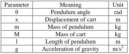
A single link inverted pendulum is shown in Figure 1. which consists of a moving cart and a rod hinged on it. Table 1 gives the different parameters of inverted pendulum.
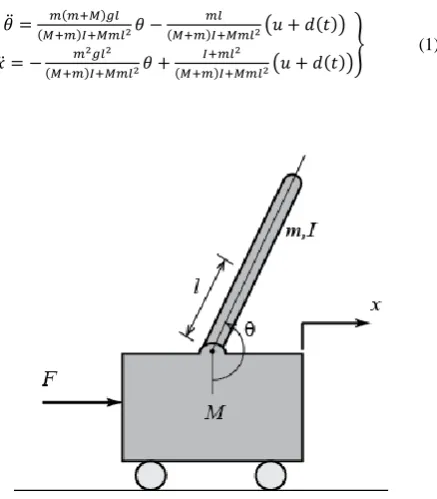
Let the pendulum is at its equilibrium point, so its linear equation is given as-
[image:1.595.318.537.491.741.2]
(1)
2
Table 1. Parameter of Inverted Pendulum
Parameter Meaning Unit
θ Pendulum angle rad
x Displacement of cart m
m Mass of pendulum kg
M Mass of cart kg
l Length of pendulum m
g Acceleration of gravity m/s2
To design sliding mode controller model should be decoupled.
Hence, defining , then ,
. Define
, and
Then,
By using decoupling algorithm,
(2)
The system under stable point when both pendulum angle and cart position both comes at rest position, means
Then
By using decoupling algorithm, we get
(3)
Let
&,
Then Equation (3) becomes
(4)
3.
CONTROLLER DESIGN
Let
Design the sliding mode controller as,
where .
Then we have
(5)
Design the sliding mode controller as
(6)
where .
Design the Lyapunov function as
,
Then
(7)
From equation (6) and (7) it is clear that, system can reach and thereafter stay on the manifold in finite time .
On the manifold, we have
, i.e. .
When , we have
where .
As ,
(8)
By comparing above equation with
To make Hurwitz, the sliding mode parameters are designed as follows:
4.
IMPLEMENTATION OF
ALGORITHM IN MATLAB
Simulation is done on MATLAB/Simulink environment to evaluate the results under various conditions (i.e. k = 10, 50, 100). Simulation results give a brief about the algorithm need to be implemented in the system.
The following parameters were chosen for simulation: M=1; m=.010; L=0.50.
The initial states are ,
and ideal position signal is set as
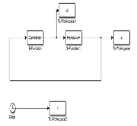
Fig. 2 shows the simulation model of controller and pendulum.
Various cases are discussed below:
Case (a): For k=10, location of pole is closer to imaginary axis which increases the damping coefficient, hence increase the settling time and slow the system response as shown in fig (3). Slower response make system less stable, as we can see in fig (4) and fig (5).
[image:3.595.54.281.71.193.2]Figure 5. Pendulum angle & speed Figure 4. Cart position & Speed
Figure 3. The response of control input (k=10)
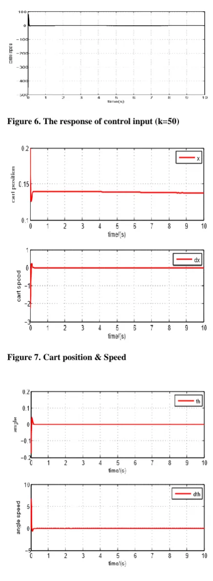
[image:3.595.318.535.128.711.2] [image:3.595.54.277.482.686.2]4 Case (b): For k=50, pole location moves away from imaginary
axis, hence the control input has been improved which is shown in fig (6).Improved control input makes cart position in fig (7) and pendulum angle in fig (8) at rest position. Hence system become more stable.
[image:4.595.317.533.122.732.2]Case (c): For k=100, poles are located in dominant pole region, which zero the damping coefficient and makes zero the transient response time as shown in fig (9).In dominant pole region cart position, fig (10) and pendulum position, fig (11) comes exactly at zero position.
[image:4.595.55.274.129.726.2] [image:4.595.320.533.138.236.2]Figure 8. Pendulum angle & speed Figure 7. Cart position & Speed
Figure 6. The response of control input (k=100)
[image:4.595.57.274.138.236.2]Figure 8. Pendulum angle & speed Figure 7. Cart position & Speed
[image:4.595.318.533.469.707.2]From above figure it is clear that, as poles are moving away from imaginary axis, control input becomes more stable, hence pendulum and cart position both comes at rest position.
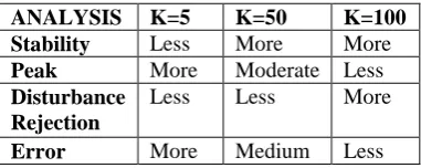
Table 2. Differences between All Cases
ANALYSIS K=5 K=50 K=100
Stability Less More More
Peak More Moderate Less
Disturbance Rejection
Less Less More
Error More Medium Less
5.
CONCLUSION
The proposed structure gives a more stable control input for Inverted Pendulum system. There is reduction in first peak of control input response in Fig. 3 & Fig. 6. As compared to the control input in the Fig 5. Thus, implying reduced disturbance in control input. As evident from Table II, disturbance rejection, error improves as value of gain K is increased. Hence, there is overall improvement in system performance.
This study has investigated performance of decoupled algorithm with varying gain on single link inverted pendulum. It would be interesting to analyse performance of decoupled algorithm on multiple link inverted pendulum. Further, fractional order sliding mode controller can be tested for its performance on both single and multiple link inverted pendulum.
6.
REFERENCES
[1] K. J. Åström and K. Furuta, "Swinging up a pendulum by energy control,"Automatica, vol. 36, no. 2, pp. 287– 295, Feb. 2000.
[2] C. W. Anderson, "Learning to control an inverted pendulum using neural networks," IEEE Control Systems Magazine, vol. 9, no. 3, pp. 31–37, Apr. 1989 [3] A. D. Kuo, "The six determinants of gait and the
inverted pendulum analogy: A dynamic walking perspective," Human Movement Science, vol. 26, no. 4, pp. 617–656, Aug. 2007.
[4] J. H. Park and K. D. Kim, "Biped robot walking using gravity compensated inverted pendulum mode and computed torque control," in Proceedings. 1998 IEEE International Conference on Robotics and Automation, Institute of Electrical and Electronics Engineers (IEEE). [5] S. Jeong and T. Takahashi, "Wheeled inverted pendulum type assistant robot: Inverted mobile, standing, and sitting motions," in 2007 IEEE/RSJ International Conference on Intelligent Robots and Systems, Institute of Electrical and Electronics Engineers (IEEE), 2007.
[6] N. Shiroma, O. Matsumoto, S. Kajita, and K. Tani, "Cooperative behavior of a wheeled inverted pendulum
for object transportation," in Proceedings of 1996 IEEE/RSJ International Conference on Intelligent Robots and Systems, Institute of Electrical and Electronics Engineers (IEEE).
[7] N. Muskinja and B. Tovornik, "Swinging up and stabilization of a real inverted pendulum," IEEE Transactions on Industrial Electronics, vol. 53, no. 2, pp. 631–639, Apr. 2006.
[8] B. Ata and R. Coban, "Artificial Bee Colony algorithm based linear quadratic optimal controller design for a Nonlinear inverted pendulum," International Journal of Intelligent Systems and Applications in Engineering, vol. 3, no. 1, p. 1, Jan. 2015.
[9] W.-D. Chang, R.-C. Hwang, and J.-G. Hsieh, "A self-tuning PID control for a class of nonlinear systems based on the Lyapunov approach," Journal of Process Control, vol. 12, no. 2, pp. 233–242, Feb. 2002. [10] K. Yoshida, "Swing-up control of an inverted pendulum
by energybased methods," in Proceedings of the 1999 American Control Conference, Institute of Electrical and Electronics Engineers (IEEE).
[11] A. Siuka and M. Schöberl, "Applications of energy based control methods for the inverted pendulum on a cart," Robotics and Autonomous Systems, vol. 57, no. 10, pp. 1012–1017, Oct. 2009.
[12] L.-X. Wang, Adaptive fuzzy systems and control: Design and stability analysis. United Kingdom: Prentice Hall Professional Technical Reference, 1994.
[13] A. Ghosh, B. Subudhi, and T. R. Krishnan, "Robust proportional– integral–derivative compensation of an inverted cart–pendulum system: An experimental study," IET Control Theory & Applications, vol. 6, no. 8, pp. 1145–1152, May 2012.
[14] O. Boubaker, "The inverted pendulum benchmark in Nonlinear control theory: A survey," International Journal of Advanced Robotic Systems, p. 1, 2013. [15] J.-C. Lo and Y.-H. Kuo, "Decoupled fuzzy
sliding-mode control," IEEE Transactions on Fuzzy Systems, vol. 6, no. 3, pp. 426–435, 1998.
[16] N. Adhikary and C. Mahanta, "Integral backstepping sliding mode control for underactuated systems: Swing-up and stabilization of the Cart–Pendulum system," ISA Transactions, vol. 52, no. 6, pp. 870– 880, Nov. 2013. [17] S. Mahjoub, F. Mnif, and N. Derbel, "Second-order
sliding mode approaches for the control of a class of underactuated systems," International Journal of Automation and Computing, vol. 12, no. 2, pp. 134– 141, Apr. 2015.
[18] V. Utkin, "Variable structure systems with sliding modes," IEEE Transactions on Automatic Control, vol. 22, no. 2, pp. 212–222, Apr. 1977.