ISSN Online: 2153-120X ISSN Print: 2153-1196
DOI: 10.4236/jmp.2018.96073 May 16, 2018 1215 Journal of Modern Physics
Euclidean Model of Space and Time
Radovan Machotka
Brno University of Technology, Brno, Czech Republic
Abstract
The aim of this work is to show that the currently widely accepted geometrical model of space and time based on the works of Einstein and Minkowski is not unique. The work presents an alternative geometrical model of space and time, a model which, unlike the current one, is based solely on Euclidean geometry. In the new model, the pseudo-Euclidean spacetime is replaced with a specific subset of four-dimensional Euclidean space. The work shows that four-dimensional Euclidean space allows explanation of known relativistic ef-fects that are now explained in pseudo-Euclidean spacetime by Einstein’s Spe-cial Theory of Relativity (STR). It also shows simple geometric-kinematical nature of known relativistic phenomena and among others explains why we cannot travel backward in time. The new solution is named the Euclidean Model of Space and Time (EMST).
Keywords
Special Theory of Relativity, Euclidean Space, Four-Dimensional Space, Time Dilation, Length Contraction
1. Introduction
Albert Einstein introduced his concept of a mutual relationship between space and time known as Special Theory of Relativity (STR) in his work Zur Elektro-dynamik bewegter Körper (On the Electrodynamics of Moving Bodies) [1]. This work was focused on solving then existing discrepancies between theories de-scribing electromagnetic phenomena on one side and classical mechanics on the other. By its nature the work is physico-mathematical and the issue of geometry is addressed only marginally. This drawback of the original theory was elimi-nated a few years later by Hermann Minkowski’s work Die Grundgleichungen für die elektromagnetischen Vorgänge in bewegten Körpern (The Fundamental Equations for Electromagnetic Processes in Moving Bodies) [2] which was
fol-How to cite this paper: Machotka, R. (2018) Euclidean Model of Space and Time. Journal of Modern Physics, 9, 1215-1249.
https://doi.org/10.4236/jmp.2018.96073
Received: March 28, 2018 Accepted: May 13, 2018 Published: May 16, 2018
Copyright © 2018 by author and Scientific Research Publishing Inc. This work is licensed under the Creative Commons Attribution International License (CC BY 4.0).
DOI: 10.4236/jmp.2018.96073 1216 Journal of Modern Physics
lowed by his lecture from 1908 Raum und Zeit (Space and Time) [3].
In his work, Minkowski connected space and time into one four-dimensional continuum, later called spacetime or Minkowski space, and he defined its key features. He introduced a specific pseudo-Euclidean metric for spacetime which is called Minkowski metric after the author. It is usually written in the form
2 2 2 2 2 2
s = ∆ − ∆ − ∆ − ∆c t x y z (1)
where ∆x, ∆y, ∆z and ∆t are coordinate increments and s is the so called space-time interval. This interval plays the same role in Minkowski space as distance plays in ordinary Euclidean space.
Minkowski based his thoughts on Maxwell’s equations of electrodynamic field and their intrinsic symmetry, which reveals itself particularly when the equations are written with time taken as an imaginary quantity. Here the main reason for the use of imaginary numbers in Minkowski theory and subsequent introduction of the Minkowski metric can be seen. Using this metric Minkowski showed that the Lorentz transformation can be understood as a rotation of four-dimensional spacetime by an imaginary angle [2]. If a well-chosen coordinate system is used, orientation of two spatial coordinates does not change during the Lorentz trans-formation (they are invariant) and the transtrans-formation affects only one space-like and one time-like coordinate. E.g. if coordinate system S' moves with velocity u with respect to coordinate system S in the direction of the axis x, the transforma-tion (rotatransforma-tion) affects coordinates x and t, while y and z remain invariant1. In this case the transformation can be written as
2 2
1
x ut x
u c − ′ =
−
, y′ =y, z′ =z, 22
2
1 u
t x
c t
u c
− ′ =
−
(2)
where x, y, z, t are coordinates of an arbitrary point in coordinate system S and x', y', z' and t' are coordinates of the same point in coordinate system S'.
Minkowski’s geometrical interpretation of Einstein’s STR was great success. It was quickly adopted as an integral part of the theory and as such, it was not questioned for years. Moreover, Minkowski metric in generalized form known as pseudo-Riemannian metric become fundamental part of General Theory of Relativity. Some doubts regarding geometry of spacetime emerged with quan-tum mechanics arrival in nineteen thirties, but no real alternative was found. The problems with Minkowski concept of spacetime accumulated over years mainly in connection with attempts of quantum gravity theory. The unsatisfac-tory situation holds till now and it is reflected in many works of contemporary scientists [4] [5] [6]. In recent years alterations of original Minkowski concept using Finsler or Cartan geometry are proposed [7] [8], but with no remarkable success.
For the whole time, Euclidean geometry was overlooked and relegated to aux-1Symbol u will be only used for mutual velocity of coordinate systems, the velocity of other objects
DOI: 10.4236/jmp.2018.96073 1217 Journal of Modern Physics
iliary roles, mainly in pedagogical tasks as a visualization tool [9] [10]. The au-thor is convinced it was great fault.
The aim of this work is to show that Einstein-Minkowski solution known as STR is not unique. There exists at least one other solution which corresponds to our observations, which leads to the same mathematical formulas, but which geometry is quite different. In reality, its geometry is Euclidean!
2. Assumptions and Methods
Let’s assume that physical space is Euclidean, i.e. the axioms of Euclidean geo-metry hold in it. Application of such an assumption on the whole universe may be difficult, but for our objectives it is sufficient to assume euclidicity of space in some local scale, that is in some restricted part of the universe sufficiently distant from mass bodies and their gravitational fields. In such a part of the universe, we can imagine existence of two inertial coordinate systems with their origins un-iformly moving each other. We will denote one of these systems as S and its axes x, y, z, the other as S' with axes x', y', z'. The coordinate time of the first system will be denoted as t, the coordinate time of the other as t'. For the sake of sim-plicity, we shall assume that the corresponding axes of both systems are parallel and the origins O and O' of the systems coincide each other at time t = t' = 0. Motion of system S' in respect to S holds in the direction of the positive semi axis x with the speed u.
2.1. Stationary Coordinate System
In further explanation we will assume existence of one outstanding coordinate system called the stationary coordinate system. In this coordinate system the light propagates with the same speed in all directions. Such a system will be de-noted as S, speed of light as c.
We will assume that in other coordinate systems that are moving with respect to S, the above claim is not fulfilled.
2.2. Time Measurement
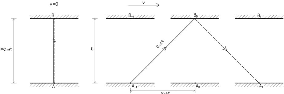
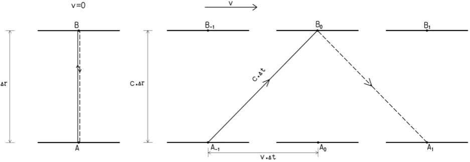
In correspondence with Einstein, we will assume that time is measured by “ideal clocks” and all such clocks give exactly the same results, if they are not moving relative each other. Such ideal clocks could be designed also as so called light clocks which measure time on the basis of motion of light pulse between two mirrors. Such a clock clearly demonstrates the slowing-down of time flow as a consequence of speed growth. The faster the motion of the clock with respect to S the longer the light pulse trajectory in one cycle and the duration of the cycle is thus longer (see Figure 1).
2.3. Distance Measurement
DOI: 10.4236/jmp.2018.96073 1218 Journal of Modern Physics Figure 1. Light clock. Time of flight of light pulse between two mirrors depends on the state of motion of the clock. On the left— clock in rest, on the right—clock moving with velocity v to the right.
end point of measured distance (point B) and received at the initial point at time
2A
t .2 The transit time is measured by an ideal clock which is placed at point A. The relevant formula is
2 0
2
A A
t t
AB = − c (3)
2.4. Clock Synchronization
In regard to coordinate time, we will assume, in correspondence with Einstein, that in given coordinate system the time is measured by a set of mutually syn-chronized clocks. A method described in Einstein’s earlier cited work will be used for the clocks’ synchronization. The method uses light signals emitted off clock A at time t0A, reflected at clock B at time t1B and received at clock A at
time t2A.
The method assumes that the speed of light is the same in both directions and thus the reflection of the signal at B occurs in the middle of the time interval bounded by the signal emission and reception at A. The midpoint of the time interval is given by the formula
2 0 1 2
A A
A t t
t = − (4)
Mutual synchronization of clocks will be done by setting the clock B in such a way that
1B 1A
t =t (5)
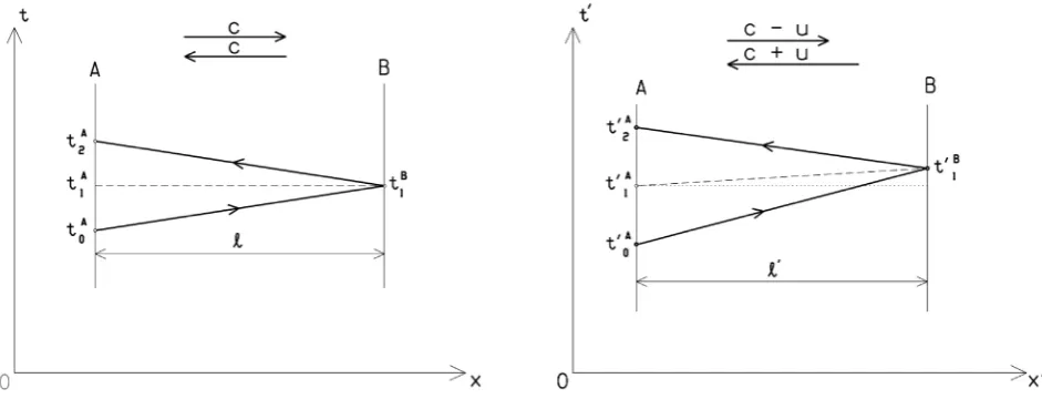
The left part of Figure 2 shows synchronization of clocks that are at rest with respect to S, the right part shows synchronization of clocks located on a moving object. The results of both synchronizations are different. In terms of coordinate time t, i.e. in terms of a stationary clock, the result of “synchronization in mo-tion” (the right part of Figure 2) is incorrect.
DOI: 10.4236/jmp.2018.96073 1219 Journal of Modern Physics Figure 2. Light synchronization of clocks A and B, at the left: clock at rest, at the right: both clocks in uniform motion to the right at speed u. Light signal speed with respect to the clocks in motion is variable (motion to the right with speed c − u, motion to the left with speed c + u).
At the end of synchronization in motion, the clocks A and B will be synchron-ous in terms of the coordinate system rigidly coupled with the object carrying both clocks (system S') (clock_shift′AB =clock_reading′B−clock_reading′A=0) and time difference between events A1 and B1 is equal to zero (∆t′AB=t1′B−t1′A=0).
The events are concurrent.
In terms of stationary system S the timedifference of the events A1 and B1 is non-zero, it equals
2
1 1 2
2
1 AB B A
ul c
t t t
u c
′
∆ = − =
−
(6a)
i.e. event B1 will occur after event A1.
As regards to reading of both clocks, for stationary observer the reading of clock B will be always smaller than reading of clock A by amount
2
clock_shiftAB clock_readingB clock_readingA ul
c ′
= − = − (6b)
Clock shift is in absolute value smaller than time difference of synchronizing events. It is result of different clocks rate. Clocks A and B moving with system S' are slower than reference clock in stationary system S (see time dilation in chap-ter 4.1).
In the Formulas (6a) and (6b) the length l' is the distance between clocks A and B measured in system S', i.e. in the system to which both clocks are at rest.
Violation of clock synchronization process is caused by different speeds of light on its way to B and back. In consequence the relevant transit times are not equal.
dif-DOI: 10.4236/jmp.2018.96073 1220 Journal of Modern Physics
ferent directions, but the result of such synchronization differ from the result of synchronization in a stationary system.
2.5. Assumptions and Methods—Summary
All assumptions and methods stated above correspond with assumptions and methods of Einstein’s STR as he introduced them in his work Zur Elektrodyna-mik bewegter Körper[1]. Einstein even uses the idea of “stationary system” in the work, he just defines it differently—through the validity of “Newtonian equ-ations”. In consequence both definitions of a stationary system are equivalent.
The only significant difference lies in the method of distance measurement. In his work Einstein assumes usage of rigid gauges—rods. As will be shown later (Chapter 4.6) both measuring methods, the one stated above and the Einstein’s, are equivalent and choice of the method has no influence on measurement re-sults.
3. Euclidean Solution
3.1. 4D Space Euclidicity Postulate
The basis for following considerations as same as for the whole Euclidean Model of Space and Time (EMST) is a formula belonging to the Einstein-Minkowski solution [3]
2 2 2 2 2 2 2
c ∆τ = ∆ − ∆ − ∆ − ∆c t x y z (7)
It is a variation of (1) that is valid in the case
2 2 2 2 2
c t∆ ≥ ∆ + ∆ + ∆x y z (8)
Fulfilling the inequality (8) is demanded in order for ∆τ to be a real.
Equation (7) can be interpreted as a relation between an increments of coor-dinate time t and proper time τ of a body that has moved uniformly between two
points in time interval ∆t, whereas coordinate differences of both points are ∆x, ∆y, ∆z. The given formula is valid for any object regardless if it is in motion or at rest with respect to chosen coordinate system. The quantity ∆τ is an invariant of the Lorentz transformation as well asspace-time interval s (s c= ∆τ).
The Euclidean formula equivalent of (7) can be acquired by a simple rear-rangement
2 2 2 2 2 2 2
c t∆ = ∆ + ∆ + ∆ + ∆x y z c τ (9)
Formulas (7) and (9) are identical from a mathematical point of view but their geometric interpretation is different. While the Formula (7) defines the Min-kowski metric s c= ∆τ in four-dimensional spacetime with three spatial axes x,
y, z and one time-like axis ct, Formula (9) defines the Euclidean metric c t∆ in four-dimensional space with spatial axes x, y, z and cτ.3 In the Euclidean con-cept the quantity t is not one of space dimensions but a measure of remoteness 3Alternate notation w of the fourth axis will be also used in this article to highlight its space-like
DOI: 10.4236/jmp.2018.96073 1221 Journal of Modern Physics
of two points of space, i.e. the distance between them.
As will be shown further, four-dimensional Euclidean space (E4) can be used as a basis of an alternative theory of space and time. On that account this space will be one of the cornerstones of EMST, its first postulate. 4D space euclidicity postulate sounds:
“Space is four-dimensional and Euclidean.”
To create a realistic theory which would comply with the mathematical aspect of Einstein’s STR it is necessary to accept two more assumptions.
3.2. 4D Speed Invariance Postulate
It can be seen from Formula (9) that no object in E4 can be stationary. Every ob-ject travels a distance c t∆ during time interval ∆t, i.e. almost 300,000 km in a second. This also holds for objects that are seemingly stationary or that move with distinctly sub-light velocities. Motion of such objects takes place complete-ly, or in the vast majority, in the fourth dimension, that is along the axis w c≡ τ. Our (three-dimensional) senses, as well as our (three-dimensional) measuring equipment, cannot detect motion in the direction of this axis. The only way we can measure it is using a clock connected to the object. Among others, the For-mula (9) expresses a known relativistic fact that the larger the change of spatial coordinates x, y and z in time interval ∆t (or more commonly said the faster the object is moving) the slower the flow of its proper time τ.
Denotations “4D motion”, “4D speed4” etc. will be used in the following text to distinguish motion in E4 from motion in ordinary three-dimensional space (E3).
A new postulate as a replacement for Einstein’s speed of light invariance post-ulate can be formpost-ulated with the use of 4D speed. This postpost-ulate is directly de-rived from Formula (9). 4D speed invariance postulate states:
“In a stationary coordinate system all objects move with the same 4D speed that is equal to the speed of light c.”
It should be noted that the postulate refers to the stationary system only, i.e. to the system in which the speed of light is invariable and equal to c. This postulate is an enhanced version of Einstein’s speed of light invariance postulate that states: “Every ray of light moves in the stationary system with the same speed c, the speed being independent of the condition whether this ray of light is emitted by a body at rest or in motion” [1].
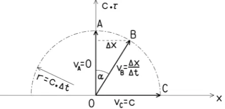
According to the 4D speed invariance postulate all objects travel the same distance during time interval ∆t. Various cases for objects moving from point 0 at different speeds v are displayed in Figure 3.
3.3. Fourth Spatial Dimension Boundedness Postulate
DOI: 10.4236/jmp.2018.96073 1222 Journal of Modern Physics Figure 3. Uniform motion of objects launched from point 0. At the end of time interval ∆t, the objects are located on the surface of a four-dimensional hemisphere with radius r = c ∆t. It is a hemisphere due to the fact that increments of coordinate cτ cannot be negative. Motion of objects in plane x – cτ is plotted here. Speed of an object can also be expressed by an angle α: sin x v
c t c
α= ∆ =
∆ .
accurately limited usable width in the direction of the fourth spatial axis
w c≡
τ
. Firstly I will clarify the reasons.Experience teaches us that two object are in collision if these occupy the same point of space at the same time. In ordinary three-dimensional space it corres-ponds to an equality of spatial coordinates x, y, z and time value t. In a four-dimensional space it would be natural to expect equality of all four spatial coordinates with coordinate w c≡
τ
among them. It can be shown, though, that in real world the collisions occur entirely independently of the value of w c≡τ
.Let us have objects A and B that are both stationary in the system S. From ob-ject A light signal L was emitted towards object B, it was reflected there and has returned back to A. On its way to B and back the light signal traveled a distance of 2||AB|| in time AA 2
AB t
c
∆ = . During this time the object A hasn’t changed
its “three-dimensional” position, thus ∆ = ∆ = ∆ =xA yA zA 0 and according to Formula (9) holds that 2 2 2 2
AA A
c t∆ = ∆c τ or c∆τA= ∆c tAA. An increment of the
fourth spatial coordinate c ∆τA of object A is equal to time ∆tAA multiplied by speed of light c. On the contrary the light signal L travels the distance c∆tAA in time ∆tAA and from Formula (9) it is clear that the increment of its fourth spatial coordinate equals zero (c∆τL = 0). If the light signal was emitted from object A at a point with coordinates xA, yA, zA, cτA then the instant of return had coordinates xA, yA, zA, c
(
τA+ ∆τA)
. On the other hand, for the light signal itself, its proper time has not flown (∆τL = 0), its coordinate w c≡τ
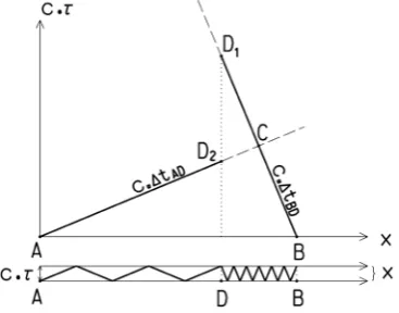
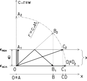
had not changed and after its return it had its initial coordinates xA, yA, zA, cτA. In terms of four-dimensional space, the light signal has returned to the initial point, but ob-ject A is no longer present here. Thus the collision, i.e. the interception of the light signal by the object A, should not take place. Physical reality, though, is different.DOI: 10.4236/jmp.2018.96073 1223 Journal of Modern Physics Figure 4. Plot of collision of two objects, at the top: in plane x – cτ, at the bot-tom: in case of existence of barriers.
x – cτ we will see that they intersect at point C. However this point will not be the place of their collision because they will not be present there simultaneously. 4D distances ||AC|| = c∆tAC and ||BC|| = c∆tBC are different which means that al-so the times ∆tAC and ∆tBC are different. In fact the two objects collide at point D which corresponds to two separate points D1 and D2 in plane x – cτ. 4D dis-tances ||AD2|| = c∆tAD and ||BD1|| = c∆tBD are equal in this case, which means that both objects will occupy point D at the same time.
In order to explain such a strange feature of space, following assumption has to be adopted, fourth spatial dimension boundedness postulate:
“Material objects are in the fourth spatial dimension limited to narrow allotted region. This region is common for all material objects and does not provide enough room for their mutual passing.”
This means, that the space and (elementary) particles of matter are four-dimensional but some forces or barriers keep them in a narrow strip of the space. The dedicated strip is very narrow, so the particles are unable to pass each other in the fourth dimension without mutual interaction. Only three remaining spatial dimensions are applicable. For the sake of completeness we should add that, due to the concentration of all matter particles in a narrow strip of four-dimensional space, all composite objects have one dimension significantly smaller than the others. Thus, even though composed of four-dimensional par-ticles, these objects exhibit only three-dimensional properties.
There certainly exists some physical explanation for the above mentioned be-havior of particles but it is unknown to the author at this time. For further ex-planation, such behavior of particles in 4D space will be thought as basic fact, and as such it is not to be discussed or investigated any further. Instead, we will focus on finding of appropriate geometrical model of particles motion.
3.4. Geometric Interpretation of 4D Motion
DOI: 10.4236/jmp.2018.96073 1224 Journal of Modern Physics
1) It holds direct proportion between particle’s 4D path increment and coor-dinate time ∆t increment expressed by Formula (9).
2) 4D speed of any particle is constant in time and is equal to c.
3) Allotted region of space E4, where all particles are situated, is too narrow in the direction of fourth spatial dimension w c≡
τ
to observe this dimension in macroscopic experiments.4) 4D trajectory of any particle is continuous, i.e. without gaps or jumps. 5) Particles obey laws of conservation of energy, momentum and mass. Direct consequence of assumption 5 is:
6) Direction of a particle’s 4D motion is changing only when it is in the inte-raction with force field, with other particle or with boundary of E4 space region. In other cases, the trajectory is straight.
Let us describe 4D motion of a particle in uniform subluminal motion. For such motion holds:
7) Projection of the particle’s 4D speed onto our ordinary three dimensional space (E3) is ordinary (3D) speed v which is constant in time and less than c.
8) Projection of the particle’s 4D trajectory onto E3 is a straight line. Using statements 1, 2 and 7 it can be stated:
9) 4D velocity component in direction of w c≡
τ
is non-zero and its absolute value is constant in time.In combination with statements 3 and 4 we acquire:
10) Due the fact that allotted region is narrow in direction of w c≡
τ
, the par-ticle is experiencing oscillating motion. The sign of velocity component in this direction is changing in time.And finally from statements 6 and 10:
11) Direction of 4D motion is changing only on the boundaries of E4, the change is abrupt a it affects only sign of the 4D velocity component in the direc-tion of w c≡
τ
.The above findings mean that 4D trajectory of uniformly moving particle − is restricted to the allotted region of E4,
− is situated in a plane given by the direction of particle’s 3D motion and pa-rallel with axis w c≡
τ
,− is composed of straight, mutually connected lines,
− its vertices rest on the barriers bounding allotted region of E4,
− its straight lines form equal angle α with the axis w c≡
τ
, the angle is given by speed v of the particle (sin vc
α= ).
Such form of motion is shown on the lower part of Figure 4. Definition:
Let us have a space E4 containing two distinct three-dimensional hyperplanes perpendicular to the axis w c≡
τ
. These hyperplanes will be called “barriers”, their distance labeled w (w w= max −wmin). Subset of E4 bounded by both bar-riers will be called space E4-B (letter B for “bounded”).DOI: 10.4236/jmp.2018.96073 1225 Journal of Modern Physics
motion.
We have space E4-B in which particles of matter are moving by speed of light. Trajectory of each particle is continuous and is composed of straight lines. Each line forms an angle α with axis w c≡
τ
proportional to the speed v of the par-ticle. Motion of the particles in the direction of three spatial coordinates (x, y, z) is considered as unrestricted, while in the fourth dimension w c≡τ
is limitedby existence of two barriers perpendicular to the fourth spatial axis w c≡
τ
. All particles of matter are located between these barriers that constitute fixed boun-daries of their motion in the fourth dimension. The distance w of the barriers is constant, independent of the type of the particles, time and position in space. As an inevitable consequence of laws of momentum, energy and mass conserva-tion, collisions of particles with the barriers are ideally elastic, particles maintain their kinetic energy (i.e. both speed and mass), 3D direction of motion and an-gles of incidence to the barriers are equal to anan-gles of reflection. Motion of par-ticles in the fourth dimension has oscillatory nature. This oscillatory motion is performed by individual elementary particles, not by objects as a whole.Described geometrical model could also hold particles in arbitrary accelerated motion. It is sufficient to drop some demands on particle’s trajectory as a result, the 3D motion of particle is now no more uniform. 4D trajectory will now be composed of lines which are no necessary straight, lay in one plane nor form constant angle with w c≡
τ
.3.5. Fourth Spatial Coordinate
In further explanation I shall distinguish between the value of coordinate
w c≡
τ
and the actual position of an elementary particle within E4-B. The laterwill be marked as wB. While coordinate wB is changing in a narrow range be-tween wmin and wmax in a cyclic manner, coordinate w c≡
τ
grows with every cycle by value of 2(wmax − wmin) (Figure 5). We have no means of measuring coordinate wB directly but by using a clock we can measure increments of w c≡τ
.Both variants of fourth spatial coordinate wB and w c≡
τ
have their theoret-ical importance. On one side coordinate wB gives the position of elementary par-ticles in the space between barriers, on the other side coordinate w c≡τ
con-nects motion of particles with time. In terms of further explanation, there is an important fact that quantity w c≡
τ
is not cyclic and thus it is suitable for plot-ting of diagrams of object’s motion. Such a diagram does not correspond to the real motion of particles in 4D space but it is much more descriptive than a plot of a trajectory with numberless reflections from the barriers. A comparison of the “real” motion between the barriers with a plot of “fictitious” motion in plane x – cτ can be seen on Figure 4 and Figure 5.A diagram with axes x and w c≡
τ
is an analogy of the commonly knownDOI: 10.4236/jmp.2018.96073 1226 Journal of Modern Physics Figure 5. Two variants of plots of a particle motion in 4D space—bold: “real” motion between the barriers, dashed: “fictitious” motion in plane x – cτ.
3.6. Geometric Interpretation of Time
We have described important features of E4-B space as well as nature of the mo-tion in it. Now, let us turn our attenmo-tion to the proper time. Proper time can be defined as an increment in coordinate w c≡ τ divided by speed c.
On the other hand, the proper time does not have to be understood solely as a distance divided by speed; there also exists an alternate view. As a natural meas-ure of time flow, the number of reflections of selected elementary particle from the barriers can be chosen. The faster the particle is reflecting, the faster the time is passing. Matter itself measures its time—each particle of matter is a ticking clock. There is a direct proportion between the number of reflections of a par-ticle n and a length of the corresponding time interval ∆τ. The proportion is given by formula
(
max min)
c∆ =τ n w −w =nw (10)
4. Geometric Basis of Relativistic Phenomena
In the previous chapter we have introduced E4-B space as a replacement for pseudo-Euclidean spacetime used in Einstein’s STR. In this chapter we shall demonstrate the geometric basis of the Lorentz transformation and known rela-tivistic phenomena of time dilation and length contraction.
4.1. Time Dilation
reflec-DOI: 10.4236/jmp.2018.96073 1227 Journal of Modern Physics
tions and the slower the oscillation. The 4D path c ∆t of a particle drifting to-gether with such a clock at speed v is given by c t2∆ = ∆ + ∆2 v t2 2 c2 τ2 (Figure
6). Hence
2 2
1 v
t c
τ
∆ = ∆ − (11)
The formula shows that the time interval ∆τ measured by a “particle clock” in motion will be smaller than the corresponding ∆τ interval measured by a refer-ence “particle clock” at rest.
The above effect affects all particles of a moving object i.e. every particle of the object behaves as a light clock. There is no difference between behavior of the matter and light in this respect.
Time behaves the same as a particle clock or light clock. This results from the direct proportion between ∆τ and the number of oscillations of a particle (see the end of previous chapter). If motion of an object is slowing down oscillations of all its elementary particles, it signifies time itself is slowing down. Thus all clocks on a moving object are slowed down in their operation, no matter their construction.
4.2. Transformation of Light Wavefront
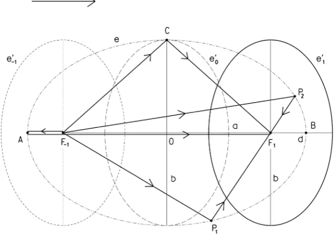
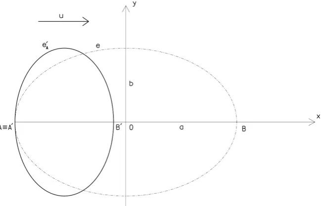
Now we shall look at the transformation of space. A geometric model of the ref-lection of light from an inner surface of an ellipsoid or sphere will be used for this purpose. Such a pair of bodies was chosen because a moving ellipsoid and a stationary sphere are equivalent bodies in terms of STR—they differ only due the length contraction in the direction of the body’s motion.
Let us have a flattened rotational ellipsoid e' moving in stationary system S with velocity u (Figure 7). Semi axis in the direction of motion shall be denoted as d, semi axis in the transverse direction as b. The two semi axes satisfy the condition d b 1 u22
c
= − . The shortening of semi axis d is chosen in such a way
[image:13.595.68.537.545.707.2]that it corresponds to the Lorentz-FitzGerald contraction. It can be verified using
DOI: 10.4236/jmp.2018.96073 1228 Journal of Modern Physics Figure 7. A view of light reflection in a moving flattened ellipsoid e' as seen in a statio-nary system S. Light emitted simultaneously from point F−1 successively reflects from the
ellipsoid: the first reflection occurs at point A, then the points of reflection gradually move to the right—towards point C and further to point B. The reflected light reaches point F1 from all directions simultaneously. The geometric set of all points of reflection is
a prolonged ellipsoid e with foci F−1 and F1.
the Lorentz transformation that in the view of system S' connected with the el-lipsoid, it appears as a stationary sphere k with radius b.
Let us assume, that in the center of a moving ellipsoid (point F−1) there is a flash of light at an arbitrary time t. The light spreads in all directions, strikes the inner mirror-like surface of the ellipsoid and reflects. The light propagates with speed c in respect to S and the ellipsoid itself is moving as well. The question is which points of S are points of light reflection and where the reflected light is heading.
It can be proved that points of light reflection from e' form a prolonged rota-tional ellipsoid e with semi axes a (in the direction of motion) and b (in trans-verse direction). The semi axis b is identical to that of a flattened ellipsoid e'. The following formulas hold for the semi axis a and eccentricity e:
2 2
1
b a
u c =
−
, 2 2
2 2
1 ub
c
e a b
u c
= − =
−
simul-DOI: 10.4236/jmp.2018.96073 1229 Journal of Modern Physics
taneously. The transit time will be
2 2 2 2 2 1 b
a c e
t
c u u
c
∆ = = =
−
(12)
The formula shows that the transit time is also the time in which center of the flattened ellipsoid e' relocates from focus F−1 to focus F1 (distance of the foci is 2e). That has consequences of great importance.
If an observer in system S sees the light being emitted and received in different points of space (points F−1 and F1) and if he is aware that reflections of light off ellipsoid e' take place successively, an observer, located in center of e' and mov-ing with it, sees the situation differently. He witnessed the light bemov-ing sent in all directions simultaneously and returning from all directions to the initial point! From his point of view, it holds F−1≡F1. Furthermore, if he assumes the speed
of light is independent of the direction, i.e. c=const., he inevitably reaches a conclusion that the reflection of light took place on a spherical surface and point
1 1
F− ≡F is in its center.
The radius of the sphere can be determined by the observer from the transit time. It holds 2r c t= ∆′ where ∆t' is time interval measured in moving system S'. This is measured using a clock moving with the system. According to (11) it applies: 2 2 1 u t t c τ ′
∆ = ∆ = ∆ − (13)
If ∆t from Formula (12) is substituted we obtain
2 2 2 2 2 2 1 1 b u b c t c c u c ′ ∆ = − = − (14)
and thus 2r c2b c
= or r = b (Figure 8).
The geometrical model described here leads to the same results as the Lorentz transformation (call to mind the choice of parameters of the flattened ellipsoid above). The moving flattened ellipsoid e' has transformed into a stationary sphere k due to change of reference systems. The model is all-Euclidean (con-trary to the Einstein-Minkowski solution), i.e. all used formulas were derived using the property of Euclidean space.
4.3. Geometric Basis of Lorentz Transformation
Using this model, let’s try to understand a geometric basis of the Lorentz trans-formation.
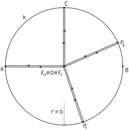
DOI: 10.4236/jmp.2018.96073 1230 Journal of Modern Physics Figure 8. Reflection of light in a moving flattened ellipsoid e′ as seen from system S′
moving with the ellipsoid. The observer is not aware that in his system the speed of light is not constant and thus interprets synchronous return of light to initial point F−1≡F1
as proof that the reflective surface has shape of sphere k with its center at point F−1≡F1.
well as proper time τ, is not changing. These coordinates perpendicular to the direction of the motion are invariants of the transformation. Therefore, the Lo-rentz transformation can be written in a modified form
2 2
1
x ut x
u c − ′ =
−
, y′ =y, z′ =z, cτ′ =cτ (15)
The discussion whether the formula for coordinate time
2 2 2
1 u
t x
c t
u c
− ′ =
−
(16)
is a linear combination of formulas stated above or a separate fifth equation shall be left for later (chapter 6.3).
It remains to explain how it is possible that the length of a moving object in Euclidean space is changing. The answer is composed of two parts.
One reason is the different view on the simultaneity of non-coincidental events. Events simultaneous in terms of system S are not necessarily simultane-ous in terms of another system (see the method of synchronization of non-coincidental clocks, chapter 2.4). It is easy to show that a flattened ellipsoid changes its appearance in conjunction with a change of simultaneity definition (Figure 9).
DOI: 10.4236/jmp.2018.96073 1231 Journal of Modern Physics Figure 9. Determination of length of moving ellipsoid. At the instant of coincidence of points A A≡ ′ the other terminal point of the ellipsoid can be either in point B'—if si-multaneity is defined using coordinate time of stationary system S—or in point B—if si-multaneity is defined using coordinate time of moving system S'.
stationary system S. The difference in x coordinates gives us its length in the di-rection of motion. We can see that the ellipsoid is flattened, i.e. its length is smaller than the transverse dimension.
2) In the second case, we use reflections of light from the ellipsoidal surface for simultaneity definition. The reflections are simultaneous in terms of system S' (reflections of light can be used for synchronization of a non-coincidental clock in S'). In case we mark position of the beginning and the end of the ellip-soid on the x axis in the moment of the light reflection, we can see that the ellip-soid is prolonged, i.e. its length is larger than the transverse dimension.
The reason for such contradictory results is the fact that in terms of S the light reflects on the trailing point (A) of the ellipsoid sooner than on the leading one (B).
It has to be pointed out that both methods of ellipsoid length determination are correct. In both cases, we have marked positions of both terminal points of the ellipsoid simultaneously. In the first case the simultaneity was in respect to system S, in the second in respect to system S'.
It is explained in the above text that, due to the method of synchronization used, the flattened ellipsoid in motion looks as if it were a prolonged one. But the text does not explain, however, why the ellipsoid appears to be a sphere to an observer in S'.
DOI: 10.4236/jmp.2018.96073 1232 Journal of Modern Physics
light wave has the form of a prolonged ellipsoid with a larger semi axis oriented in the direction of the system motion. The center of such ellipsoid is moving along with the system S'. The speed of light in the direction of motion can be determined by combination of Formulas (13) and (12)
2 2 2 2
2
1 1
x a c t c
c
t u u
t
c c
∆
= = =
′ ∆
∆ − −
(17)
as well as the speed of light in the perpendicular direction
2
y b
c c
t
= =
′
∆ (18)
The ratio of both velocities is 1: 1 22
u c
− . Notice that cx is larger than the 1
speed of light in a stationary system. This is caused by clock deceleration in a moving system.
Thus the light in a moving system behaves differently than in a stationary sys-tem. Let’s assume that an observer in system S' is not aware of the dependency of speed of light on the direction of its propagation. Due to the assumption of inva-riable value of c he will consider the simultaneity of reflections from the body to be a proof of its spherical shape. Such a claim will be supported by the fact that the light reflects back to the point of its emission.
The second part of the mystery of transformation of a flattened ellipsoid into a sphere is thus connected to the non-constant speed of light in a moving system. If we look at the parameters of ellipsoid e, we will see that the ratio of its longer semi axis to the semi axis in perpendicular direction is 1: 1 u22
c
− which is
equal to the ratio of the speed of light in direction of the longer semi axis and the speed in a perpendicular direction. Both effects fully compensate each other and they are thus undetectable by any measurement in S'. So nothing prevents an observer in S’ from accepting the assumption that the speed of light is constant in all directions.
From a mathematical point of view the transition between the prolonged el-lipsoid and a sphere is solved by changing the length scale of axis x. The unit of length on axis x' will be chosen 2
2
1
1 u
c −
times larger than on axis x. This new
unit of axis x' assures that the speed of light in S' is direction independent and the prolonged ellipsoid e transforms in sphere k. From a geometrical point of view space undergoes an affine transformation.
DOI: 10.4236/jmp.2018.96073 1233 Journal of Modern Physics
4.4. Transformation of Motion of Mass Objects
So far we have demonstrated that using the light an observer in S' cannot detect that the lengths and the entire space are affine deformed in his coordinate sys-tem. In other words, he cannot detect that the body from which the light reflects is not a sphere but an ellipsoid. It remains to be shown that affine deformation of a moving system cannot be detected by other types of measurements as well.
Let us investigate length measurements based on measurements of transit times of mass objects moving with speeds smaller than that of light. These ob-jects will behave the same way as light (with an exception of the speed of propa-gation)—their motion will be uniform and their reflections ideally elastic. We can imagine them as idealized tennis balls.
Our current model of sphere/ellipsoid has to be expanded by adding a fourth dimension w c≡ τ. The reason is simple: so far we have modeled propagation of light. Light moves at speed c and proper time doesn’t flow for it. Now we will explore slower motions and the cτ coordinate will acquire non-zero values.
Three-dimensional bodies—a sphere and ellipsoid—will be replaced by their four-dimensional variants. However, these will differ relatively little from their three-dimensional relatives. E.g. a four-dimensional flattened ellipsoid has four semi axes from which the one oriented in the direction of motion is the shortest; the remaining three are equal each other. Thus to describe the ellipsoid, it is enough to know the length of its two semi axes—the semi axis d in the direction of motion and the semi axis b in perpendicular direction. These quantities are the same as those used to describe the three-dimensional variant of this ellipsoid. We retain unchanged labeling also for the quantities of a prolonged ellipsoid (semi axes a and b) and a sphere (radius r).
We cannot imagine given bodies as a whole. Regarding further explanation, it is not a major drawback though. It suffices to neglect one of the dimensions of the four-dimensional ellipsoid and it becomes an ordinary three-dimensional lipsoid; if we omit two dimensions, we get a two-dimensional section of the el-lipsoid.
Such a section will suffice for further explanation, because we will study uni-form motions only. Applied to moving bodies such as a sphere or ellipsoid, the plane of the section will always be chosen in such a way that it includes the cen-ter of the body and the direction of its motion—the axis x. As a result of rota-tional symmetry all sections of this type are similar—i.e. the shape of the section is independent of the choice of its second dimension; it could be either y, z, cτ or any other direction perpendicular to the direction of motion.
Let us conduct an experiment: Tennis balls were launched from a point that does not move with respect to S. Each one of them moves in a different direction and different speed. In the direction of motion of each ball a solid reflective pan-el is positioned perpendicularly to this direction, so the ball is reflected back to the launch point.
DOI: 10.4236/jmp.2018.96073 1234 Journal of Modern Physics
return to the launch point at the same time. Let us suppose that in free space the balls move uniformly and reflections do not alter their kinetic energy and thus their speed. Now it is certain that reflections of all balls happen simultaneously, i.e. times of flight there and back are equal. Using the 4D speed invariance post-ulate we determine that equal transit time ∆t means that the 4D paths of all balls must be equal as well. In the moment of reflection all balls are located on the surface of the four-dimensional hemisphere with radius
2 t
r c= ∆ (see Figure
3).
Note: Mentioned hemisphere is of course a mere fiction as well as coordinate
w c≡
τ
. As a consequence of reflections from the barriers the motion of balls won’t be straight and the hemisphere will transform into a narrow object squeezed between the barriers limiting motion in the fourth dimension. Incre-ments of coordinates x, y, z and w c≡τ
as well as the 4D paths of any objects will not be affected by this transformation though.Now let us place an unchanged device with the experiment so that it is in rest in moving system S'. In terms of S it will be shortened in the direction of its mo-tion (in correspondence with Lorentz transformamo-tions). The ratio of the new and original length will be 1 22 :1
u c
− .
If we repeat the experiment described above, an observer in S' will see it iden-tically as an observer in S had before. All reflections will be simultaneous in re-spect to S' as well as return of balls to the launch point. The observer will be able to verify simultaneity of reflections by means of clocks placed at the reflective panels and synchronized using the light. He will not detect any deviation.
The observer in S, though, will see the course of the experiment differently. From his point of view, the points of launch and reception of balls will not be the same. Also times of reflections of balls will differ. On the other hand, he will not question the fact that all balls were launched simultaneously and they also return simultaneously. Using the 4D speed invariance postulate he will determine that all balls travel the same 4D distance. Because they were launched from one point and after reflection returned to another one, he will easily determine that all points of reflection must be located on the surface of a prolonged four-dimensional el-lipsoid. The points of launch and reception of balls are the foci of this ellipsoid (or semi ellipsoid, if increments of coordinate w c≡
τ
on the way to the reflec-tive panels will be regarded as posireflec-tive and on the way back as negareflec-tive).Parameters of the ellipsoid can be determined from the balls’ travel time. For a longer semi axis applies 2a c t= ∆ , for eccentricity 2e u t= ∆ . Given values can be compared to parameters of the prolonged ellipsoid e created by reflections of light—see Formula (12). They are identical!
4.5. Analogy between Motion of Mass Objects and Motion of Light
DOI: 10.4236/jmp.2018.96073 1235 Journal of Modern Physics
Just the same way we have described motion of light in the sphere/ellipsoid model by means of three interchangeable bodies—flattened ellipsoid, prolonged ellipsoid and sphere, we can describe motion of balls. The only difference is usage of a four-dimensional variant of the bodies. We have a moving flattened ellipsoid with semi axes d b 1 u22
c
= − and b representing a moving device with
the experiment, sphere of radius r = b moving with S' representing a set of ref-lection points of balls as they appear to an observer in S', and a prolonged ellip- soid with semi axes 2
2
1
b a
u c =
−
and b representing a set of reflection points as
they appear to an observer in S.
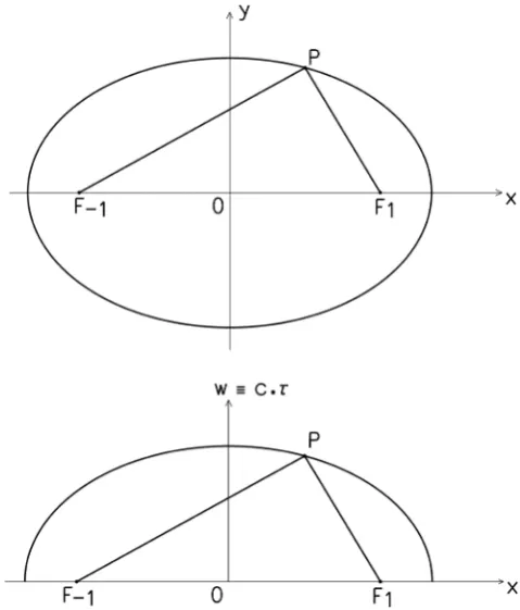
Correspondence of all parameters of given bodies has a simple explanation, it is result of equivalence of both types of motion. Whether we use the light mov-ing with speed c or tennis balls movmov-ing considerably slower, the 4D path is al-ways the same d4D=2a c t= ∆ . The only thing it changes is its projection to the three-dimensional space.
[image:21.595.252.492.384.665.2]If we plot motion of a light beam and a ball in corresponding cross-sections of a four-dimensional ellipsoid we get two variants of the same picture (Figure 10). The only difference is one axis label.
DOI: 10.4236/jmp.2018.96073 1236 Journal of Modern Physics
Partial conclusion: Results of length measurements based on measurements of moving objects’ (photons, balls, ...) transit times transforms in compliance with Lorentz transformation. They do not depend on the speed of the objects used for length measurement. If the simultaneity of light reception in the sphere/ellipsoid model led us to the change of the axis x' length scale, results of all other length measurements based on objects motion will lead us the same way.
4.6. Contraction of Rigid Rods
Only one hope remains for determination of real undeformed dimensions of a moving body. That is measurement by means of rigid measuring rods. With their help, is it possible to reveal that what seems to be a sphere, is a flatten el-lipsoid in reality?
We must reply: no. The shape and dimensions of rigid bodies are given by forces acting between individual particles of mass. These particles are not in di-rect contact and thus action at a distance is responsible. Strong and weak nuclear interactions act in the atomic nuclei, electromagnetic force between nuclei and electrons shells as well as between adjacent atoms, and all is complemented by gravitational force. All these interactions are, according to modern theories, me-diated by exchange of mass particles (mesons, leptons, photons, gravitons). These particles are in permanent motion and their interactions keep the dimen-sions of rigid bodies unchanged.
How would the distance of two adjoining ions in a crystal lattice be affected by motion of the whole body? Will it remain unchanged? On the basis of the tennis balls experiment we must say no. The particles mediating interactions are only “tennis balls”, in their nature, i.e. objects moving there and back with any speed less or equal to the speed of light. Thus during the motion of objects in S the distances between adjoining ions (atoms, molecules, nucleons, ...) are shortened. Such shortening will have the same ratio in which the sphere moving in S had to be shortened, so that it still appeared to be a sphere in view of S'. Shortening of distances between ions in a crystal lattice will inevitably lead to the shortening of the whole body. This shortening occurs only in the direction of the motion and the shortening is real. A similar explanation of length contraction was sug-gested by Lorentz in his work Electromagnetic phenomena in asystem moving with any velocity smaller than that of light [11].
It remains to add the obvious—the same reason will cause that all bodies, not just measuring rods, will be deformed the same way. The phenomenon also af-fects liquids and gases which will change their volume.
5. Equivalence of Coordinate Systems
Let’s review conclusions concerning deformation of bodies and coordinate sys-tems:
DOI: 10.4236/jmp.2018.96073 1237 Journal of Modern Physics
of bodies which are stationary in this system. The bodies and measuring rods are equally shortened which gives an impression that nothing is shortened.
2) As a result of length deformation of all measuring devices in moving coor-dinate system S’ a different length unit is used on axis x’ than on the remaining axes. Thus the coordinate system S’ is affine deformed relative to the system S. Affine deformation affects not only lengths but also angles which is why the de-formation doesn’t reveal itself by any measurement inside the moving system. It can be detected only if we compare results of measurements in two systems that are moving each other.
3) Use of an affine deformed coordinate system prevents us from detection of the directional dependence of speed the light propagates with. Variations in the speed are fully compensated by deformations of rigid rods (compare Michel-son-Morley experiment) as well as the coordinate system itself. The speed of light in a moving system appears to be identical in all directions and it is equal to the speed of light in a stationary system.
The above implies that no observation inside a moving system can detect its motion. Neither speed, direction nor any other sign of motion can be detected. This theoretical fact is supported by results of countless experiments and it stood at the birth of Einstein’s STR. Thus in the real world the stationary coordinate system cannot be distinguished from the others.
5.1. Relativistic Effects as a Result of Partial Geometric-Kinematic
Phenomena
Relativistic geometric effects (Lorentz transformation, length contraction, time dilation, ...) are products of composite action of five fractional, relatively inde-pendent phenomena:
1) Galileo transformation. This is a transformation between two coordinate systems in Euclidean space. It solves transition from the stationary to a moving coordinate system without considering relativistic effects. Its equations are
x x ut′ = − , y′ =y, z′ =z, t t′ = (19) 2) Time dilation. The dilation of time causes a slowing down of clocks in a moving system. The cause for this slowing was explained in chapter 4.1.
3) Rigid bodies contraction. As a result of this phenomenon a real shortening of bodies in the direction of their motion takes place. The degree of this effect depends on their speed in respect to the stationary system S. The shortening is in the ratio 1 u22 :1
c
− and its cause is described in the chapter 4.6.
4) Different understanding of simultaneity of events. As a result of a different outcome of clock synchronization in a moving system and in the stationary sys-tem the results of length measurements differ in these two syssys-tems. If clocks from a moving system are used all bodies seem longer in the direction of their motion than in case of use of clocks from the stationary system. Prolongation is
in the ratio 1: 1 22
u c
−
DOI: 10.4236/jmp.2018.96073 1238 Journal of Modern Physics
5) Affine deformation of moving coordinate systems. A change in the scale of axis x' causes an apparent shortening of bodies in the direction of their motion in the ratio 1−uc22 :1.
The partial phenomena described above are of a geometric or geome-tric-kinematic nature. This nature is known for all of these phenomena for a long time, but it is not widely accepted in the case of two of them. This concerns items 2) and 3).
In particular situations not all of these phenomena have to participate. E.g. in the Lorentz transformation only phenomena 1), 2), 4) and 5) take effect, whereas the explanation why the length of a body, in terms of a coordinate system rigidly coupled with it, does not change after acceleration is caused by the interaction of phenomena 3), 4) and 5).
5.2. Relativity of Relativistic Effects
As is known, all relativistic effects are relative, i.e. they occur as a result of a rela-tive motion of one system against another. Their significant feature is this: in the case of an interchange of the reference and observed system the nature of ob-served phenomena does not change. E.g. if clock A in motion in S is slower than clock 0 stationary in this system it must identically apply that clock 0 in motion in S’ will be slower than clock A stationary in this system. Einstein’s STR has postulated this relativity of phenomena; for the Euclidean model it is necessary to prove it.
Let us have a clock 0 located at the initial point (x0 = 0) of a stationary system S and a pair of clocks A (x'A = 0) and B (x'B = b') in a moving system S'. System S' moves in the direction of the positive semi axis x with speed u so that at first clock B and then clock A will pass the stationary clock 0 (Figure 11). In the ex-periment we shall try to compare coordinate time of the moving system S' (ma-terialized by clocks A and B) with the time measured by stationary clock 0. In further explanation I will judge time differences and simultaneity of events from the viewpoint of stationary system S.
Clocks A and B are stationary in the system S' and they are mutually synchro-nized in this system as well (clock_shift′ =AB 0). Shift of the clocks from the viewpoint of system S should be according to (6b) clock_shiftAB 2
ub c
′ = − (the
reading of clock B is smaller than the reading of clock A).
In the instant of the passing of clock A by clock 0 (event “0A”) the time on both clocks is equal to zero 0
0
clock_reading A=0, clock_reading0AA =0. The time of clock B is smaller than the time of clock A, i.e. clock_reading0BA ubc2
′ = − .
Once before, clock B passed clock 0 (event “0B”). Clock 0, stationary in S
showed at that time less by
2 2
1 u b
b c
u u
′ −
DOI: 10.4236/jmp.2018.96073 1239 Journal of Modern Physics Figure 11. Motion of clocks A and B along with the system S'. Left: instant of mutual passing of clocks B and 0, right: instant of mutual passing of clocks A and 0.
showed less by
2 2
1 u
b c u
′ −
(they are slower).
Thus clock 0 showed time
2 2 0
0
1 clock_reading B
u b
c u
′ −
= − , clock A time
2 2 0
1 clock_readingA
B
u b
c u
′ −
= − and clock B time
2 2 0 2
1 clock_readingB
B
u b
c
ub b
u u
c
′ −
′ ′
DOI: 10.4236/jmp.2018.96073 1240 Journal of Modern Physics
Quantities clock_reading0AA and clock_reading0BB denote times on clock A and B in the instants of their pass by clock 0.
Time
2 2
0 0
0 0
1 clock_reading A clock_reading B
u b
c t
u
′ −
∆ = − = has elapsed be-
tween the two events (first and second passing of clock) in the time scale of clock 0 (system S), whereas in the time scale of mutually synchronized clocks A and B (system S') time t clock_reading0AA clock_reading0BB bu
′ ′
∆ = − = has elapsed.
Time measured in the stationary system S is thus smaller than time measured in the moving system S'. Any observer moving with system S' observes that clocks in the stationary system S are slower than his own clock. This finding corresponds with reality as well as with Einstein’s STR.
The relativity of other phenomena can be similarly proved. It turns out that in terms of relativity all results of EMST are identical with results of STR!
5.3. Equivalence of Inertial Coordinate Systems
Even though the previous explanation was based on an existence of a “stationary coordinate system” that differs from all other coordinate systems in at least three aspects—the speed of light is independent of the direction of its propagation, coordinate time flows faster than proper time of all moving objects, the length scale of all axes is the same—we have to state now that such a coordinate system is undistinguishable from other (inertial) coordinate systems. As a result of an interaction of the five partial geometric-kinematic phenomena described above, all systems look the same and no physical experiment can determine whether the given system is moving or not. Thus we can state: Every inertial system be-haves like a stationary system.
This fact can be considered as an equivalent of Einstein’s relativity postulate which states “All inertial coordinate systems are equivalent as far as the laws of physics are concerned”.
In the Euclidean model of space and time this fact is a result of the 4D speed invariance postulate. Since we know that all inertial systems are equivalent we can derive a new, more general statement from the 4D speed invariance post-ulate that excludes the demand on system’s stationarity:
“In any inertial coordinate system all objects are moving with 4D speed that is equal to the speed of light c.”
5.4. Note to Coordinate Systems
In four-dimensional space all objects are traveling at the speed of light, but the same cannot be allowed for coordinate systems. First—such coordinate systems cannot be inertial (as a result of oscillation in the fourth dimension), second—
DOI: 10.4236/jmp.2018.96073 1241 Journal of Modern Physics
significant for coordinate system definition. Only the object’s position and its state of motion in ordinary three-dimensional space are significant. This posi-tion and state of moposi-tion are a projecposi-tion of 4D posiposi-tion and 4D moposi-tion into three-dimensional space. In reality the projection is done by simply omitting the fourth dimension. In this work coordinate systems are always connected with the projection of a chosen object into three-dimensional space and do not move in the fourth dimension.
6. Space and Time
6.1. Number of Dimensions
This work assumes an existence of four-dimensional Euclidean space E4-R which replaces the four-dimensional pseudo-Euclidean spacetime of Einstein-Minkowski solution. In the Euclidean solution, it is necessary to decide whether to consider time as an independent quantity, i.e. a fifth dimension of “Euclidean spacetime” or merely as a function of spatial coordinates. If we specify position of an object in E4 by its spatial coordinates x, y, z and w c≡ τ, the coordinate time remains still unknown. E.g. if all four coordinates of two objects are identical we are still unable to decide whether these two objects are in collision or not (see point C on Figure 4). The situation will not improve even if we replace the cτ coordinate with coordinate w. It would seem that coordinate time t cannot be determined from spatial coordinates and thus it is an independent quantity—it is a fifth di-mension of our world.
On the other hand the Formula (9) relates an increment of coordinate time ∆t to the change of spatial coordinates x, y, z and w c≡ τ. However, the formula can be applied to uniform translatory motion only. Nevertheless, its validity can be extended to a motion not maintaining direction nor velocity by simply divid-ing such a motion into infinitesimally small parts in which the motion is uni-form. Then, the increment of time is
2 2 2 2 2 2 2
c tδ =δx +δy +δz +cδτ (20)
Through integration of this formula over the motion’s trajectory we can de-termine the time interval separating end of the motion from its beginning. This interval is, of course, directly proportional to the length of 4D trajectory.
In case of a change of the reference coordinate system (Lorentz boost) the in-crements of time δt transform in correspondence with Formula (20). In the new
coordinate system the coordinate increments in axes x, y and z will be generally different, while the increments in cτ axis will not change.
Let us assume that two objects were located at point A in time t0, i.e. they were in coincidence, which is expressed by equality of coordinates x, y, z. Then they moved along different trajectories and in time t1 they met again at point B. The necessary condition of a second encounter is equality of lengths of their 4D tra-jectories marked by the end points A and B,
( )
2( )
41D 4D
d AB =d AB .
DOI: 10.4236/jmp.2018.96073 1242 Journal of Modern Physics
will change, as well as the coordinate increments and 4D paths of both motions. However, even after the transformation, the equality
( )
2( )
41D 4D
d′ AB =d′ AB will apply, i.e. both trajectories transform in such a way that the lengths will be equal again. This is true, of course, only in the case that both trajectories share their initial and end points.
The possibility of determination of increments of coordinate time by formulas (9) and (20) is not only restricted to real motions. It can be also used for imagi-nary motions. The only two conditions are the unambiguous definition of the motion’s trajectory and the fact that such a motion can be accomplished. The latter condition is expressed by inequality Formula (8) and can be interpreted as a requirement that speed of the motion cannot exceed the speed of light c.
As a conclusion we can state that in all such cases where a time-like relation between the events exists, i.e. in cases in which it is possible to accomplish a mo-tion originating in one event and ending in the other, the increment of coordi-nate time is a function of the motion’s trajectory. In other words, it is a function of the object’s coordinates change over the time. In such cases where the time relation between events doesn’t exist any functional relation between coordinate time and coordinates is non-existent as well. Mechanical usage of Formula (9) leads to the necessity of introduction of an imaginary proper time. Such a quan-tity, however, has no physical meaning and so such an approach has to be re-jected.
6.2. Definition of Space
From the above consideration we can see apparent theoretical difficulty in defi-nition of space and objects in it as a physical reality without any connection to the past. Such an approach would necessitate introduction of a fifth independent coordinate—coordinate time, while according to other considerations this coor-dinate cannot be independent. Thus in terms of presented Euclidean theory of space and time it is necessary to define space as a set of objects that has traveled to their current positions by unknown, but quite specific, trajectories. Existence of such trajectories is necessary for time location of those objects as well as events which the objects are participants. The formulas (9) and (20) allow no more than determination of time increments from some given event in the ob-ject’s history. So for an evaluation of equality of coordinate times of two objects which are in the same point of space it is necessary to accept an important as-sumption, —these two objects have met at least once in their past. This assump-tion can be ensured in the only possible way—all the trajectories have a common initial point, i.e. once in the past all the objects simultaneously emerged from one common origin.