© 2019, IRJET | Impact Factor value: 7.211 | ISO 9001:2008 Certified Journal | Page 1626
Effect of Change of Parameters on Bending Stress in Gear
Tanmay M. Gadre
1, Swapnil Vyas
2, Yash Talwar
3, Prof. Pradeep K. Mehta
41 Student, Dept. of Mechanical Engineering, Medi-Caps University, Indore, India
2 Student, Dept. of Mechanical Engineering, Medi-Caps University, Indore, India
3 Student, Dept. of Mechanical Engineering, Medi-Caps University, Indore, India
4 Professor, Dept. of Mechanical Engineering, Medi-Caps University, Indore, India
---***---Abstract –
Bending Stress plays a major role in giving ahelping hand in the failure of gear sets these days. Thus, analysis of these common stresses are popular areas of research to observe decrement in the failures and for optimal design of gears. Work done herein will look for the effect of tooth parameters monitoring the stresses induced on spur gear by optimizing face width, root fillet radius, and number of teeth relative to weight of spur gear set. The Study will be conducted by varying the face width, number of teeth and root fillet radius to find its effect on the bending of spur gear.
Key Words: Bending Stress, FEA, Lewis and AGMA
Equations
1.INTRODUCTION
Gear transmission systems are everywhere these days and also they play important role in industries. Gears in mesh experience two types of cyclic stresses namely: bending stresses and Contact Stresses. These types of stresses may not attain their maximum values at the same point of contact. Adequate knowledge and understanding of such gear behavior in contact such as stress distribution, work condition and distortion is critical to monitoring and controlling the gear transmission system [1].
However, combined action of both of these is the reason of failure of gear tooth leading to fracture at the root of a tooth under bending fatigue and surface failure, like pitting. This failure can be diminished by careful analysis of the problem during the design stage and creating proper tooth surface profile, optimal teeth parameters with proper manufacturing methods studied by David et al. (2013) [2]. They form the most important components in power transmission systems. Gears generally fall out when the working stress exceeds the maximum permissible stress.
1.1Objective
The objectives of the study will be to:
Model and simulate the spur gear set using software packages CATIA and ANSYS Workbench.
Compare the results obtained by FEM and AGMA standards.
1.2 Methodology
The following methodology are employed to achieve the above objectives are –
a) Literature Survey - Literature survey of the material on stress analysis of gear has been done. The literature available are from various sources such as electronic media, journals, and books.
b) Modelling and FEM Analysis – The aforementioned data collected are analysed by CATIA and ANSYS Workbench.
2. PROCEEDINGS
© 2019, IRJET | Impact Factor value: 7.211 | ISO 9001:2008 Certified Journal | Page 1627 The project work we are working on is about
the reduction of the stresses particularly bending stresses.
Bending Stress - Bending stress is the normal stress that is induced at a point in a body subjected to loads that cause it to bend.
2.1 Calculations and Formula used
For Bending stress, the following AGMA formula
is used where,
– Bending Stress - Dynamic Factor
– Maximum Force P - Pitch
F – Face width
y – Modified Lewis Form Factor = 0.322 But pitch, P is , where
m – module
For Z=20, F=30, R=1.5
For Z=20, F=35
For Z=20, F=40
For Z=20, F=45
For Z=23, F=30 y=0.334
For Z=23, F=35
For Z=23, F=40
For Z=23, F=45
For Z=25, F=30 y=0.3415
For Z=25, F=35
For Z=25, F=40
© 2019, IRJET | Impact Factor value: 7.211 | ISO 9001:2008 Certified Journal | Page 1628
[image:3.595.40.553.58.784.2]3. MODELLING OF GEAR
Table -1: Dimensions Used
Input parameters
Symbol Values
Normal Module m 4
Number of gear teeth
Z1 20,23,25
Number of pinion teeth
Z2 20,23,25
Pitch circle diameter of gear
d1 80mm, 92mm,
100mm
Outer circle diameter of gear
do 88mm,
100mm, 108mm
Base circle diameter of gear
db 75.18mm,
84.65mm, 94mm
Root circle diameter of gear
dr 70mm, 82mm,
90mm
Pitch circle diameter of
pinion
d2 80mm, 92mm,
100mm
Outer circle diameter of
Pinion
do 88mm,
100mm, 108mm
Base circle diameter of
Pinion
db 75.18mm,
86.45mm,94m m Root circle
diameter of Pinion
dr 70mm, 82mm,
90mm
Normal Pressure angle
Α 20
Applied Torque T 100N.m
Face width for pinion and gears
B 30mm, 35mm,
40mm,45mm
Addendum ha 11*m
Dedendum hd 1.25*m
Root fillet radius rf 1.5mm, 2mm,
2.5mm,3mm
Fig -1: Modelling of 20, 23 & 25 no. of teeth
Using all the parameters mentioned in the table we created a few gears sets on CATIA and transferred them all to the ANSYS Workbench for further analyses on them by FEM. The gears made were by parametric and were of involute
© 2019, IRJET | Impact Factor value: 7.211 | ISO 9001:2008 Certified Journal | Page 1629
3.1
Boundary Conditions
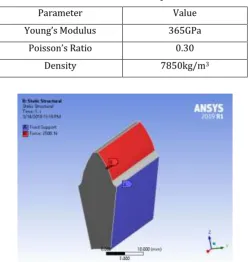
[image:4.595.316.555.98.284.2]For accurate results, boundary conditions are to be applied at the exact location it is intended to be. The following table describes the material properties considered for this study and the data is fed in the ANSYS workbench under Engineering Data for applying those material properties to the analysis. The table is for SCM420 or more commonly known as ASTM4118, which is an alloy of Chromium and molybdenum usually used for transmission gears. This improved alloy has more strength and toughness while exhibiting enhanced machinability.
Table – 2: Material Properties
Parameter Value
Young’s Modulus 365GPa
Poisson’s Ratio 0.30
[image:4.595.36.286.282.545.2]Density 7850kg/m3
Fig 2 – Boundary Conditions for Bending Stress
4. FINITE ELEMENT ANALYSIS
Finite Element Analysis or FEM for short is an effective and time conserving step implemented by engineers and researchers for carrying out larger complex simulations and calculations. In our study for carrying out analysis, the mesh/element size for the gears is kept at 1mm throughout for bending apparatus. Therefore Finite Element Method is widely used for the stress analysis of gears. In this dissertation work finite element analysis is carried out in ANSYS Workbench 2019 R1 and 16.2 to determine the bending for SCM420 (ASTM4118) steel gears.
Fig 3 – The meshing of the gears for Bending Stress
Fig -4: Bending Stress for 1.5mm fillet radius
[image:4.595.328.541.333.498.2] [image:4.595.328.539.527.691.2]© 2019, IRJET | Impact Factor value: 7.211 | ISO 9001:2008 Certified Journal | Page 1630 Fig -6: Bending Stress for 2.5mm fillet radius
Fig -7: Bending Stress for 3mm fillet radius
5. RESULTS
The percentage reduction in bending stress of gears for 20, 23, 25 number of teeth is 26.63%, 39.67% and 15.21% respectively. Graphical comparison of the above solutions are plotted for bending stress.
Chart 1– Comparison of 20 number of teeth gear
Chart 2– Comparison of 23 number of teeth gear
Chart 3– Comparison of 25 number of teeth gear
3. CONCLUSIONS
This study is based on the numerical and analytical analysis of Bending Stress by changing parameters of the gear teeth. Here the main objective is to increase strength of spur gear tooth by varying the parameters in the best way to suit different types of conditions. From this we can see that the stress at the interface and fillet region decreases with increase of parameters such as face width, number of teeth and root fillet radius. The FEA results are found to be close with the calculated stresses based on AGMA standards, and Lewis Equation.
REFERENCES
[1] Esayas Lateno, EFFECT OF CHANGE OF SPUR GEAR TOOTH PARAMETERS ON BENDING AND CONTACT STRESSES, Addis Ababa, Ethiopia, October 2014. [2] David Guyonneau, Emmanuel Mermoz, Stress
optimization and study of the sensitivity to geometric variations of a spur gear tooth profile, Journal of Mechanics & Industry 14, 31–41 (2013)
[image:5.595.55.267.293.457.2] [image:5.595.37.299.568.714.2]© 2019, IRJET | Impact Factor value: 7.211 | ISO 9001:2008 Certified Journal | Page 1631 [4] A. Kahraman, A.A. Kharazi, M. Umrani, 2002. A
deformable body dynamic analysis of planetary gears with thin rims. Journal of Sound and Vibration
262 (2003) 752–768.
[5] Chabert, G. T Dang Tran, R.Mathis, 2012. An Evaluation of Stresses and Deflection of Spur Gear tooth under strain. Journal of Engineering for Indusry,
1974, pp 85-93.
[6] F. K. Choy, M. J. Braun, V. Polyshchuk, J. J. Zakrajsek, D.
P.Townsend, and R.F. Handschuh, 1994.
[7] Analytical and experimental vibration analysis of a
faulty gear system. American Gear
Manufacturers Association, St. Louis, Missouri, October
24-26, 1994.
[8] Robert Basan, Marina Franulovic, and Bozidar Krizan, 2008. Numerical model and procedure for determination of stresses in spur gear teeth flanks. XII International Conference on Mechanical
Engineering-Nov 2008.