Teaching the Implementation of Digital Control using
Proteus VSM Software
Getu Gabisa
Addis Ababa Instutute of Technology, Addis Ababa University
Addis Ababa, Ethiopia
Mengesha Mamo
Addis Ababa Instutute of Technology, Addis Ababa University
Addis Ababa, Ethiopia
ABSTRACT
Most laboratory instruments to teach digital control systems are expensive to afford and not easily available especially in developing countries. In addition to this, even in developed countries, they are not open for basic exercising. This paper proposes a solution to this problem. It shows how to teach the fundamentals of digital control without using hardwares. It solves this problem by using Closed Loop Speed Control System of DC Motor on Proteus VSM (Vertual System Modelling) software. The encoder pulses are used to measure the speed of the motor. A PI controller is developed based on the dynamic model of the Proteus DC motor. The PWM which is produced depending on the error and the PI control algorithm is in put to L298 H bridge IC to drive the motor. The processor used is arduino uno board (ATmega328P) which is simple to program and has many libraries. The speed time response of the Proteus VSM motor is plotted using MATLAB .The communication between MATLAB and Proteus VSM arduino is realized using virtual serial communication.
General Terms
Control system, Computer application, Simulation
Keywords
Arduino, ATmega328P, DC motor, Teaching Digital control, PWM speed control, Proteus simulation, speed control
1.
INTRODUCTION
In recent years ,due to the advent of low cost, low power, light weight, fast digital processors, and flexibility ,digital control system is becoming more and more common[1][2][3]. The laboratory-based teaching of this course is key to keep the intellectual content as high as possible [4]. As reported in 1989, Stanford University upgraded its digital control lab using IBM PC to teach real time control theories [4].
Direct current (dc) machines have been in service for more than century [5]. They are still the commonly used machines as variable speed drives because of their simpler modeling than AC machines [6]. So, they play a crucial role in research, industry and laboratory experiments [8]. Therefore, they are suitable to teach control theory fundamentals.
Microcontrollers are reliable instruments to control the speed of different size DC motors with very high precision [11]. Most modern microcontrollers include built-in A/D and D/A converters [7]. The use of standalone microcontroller for speed control has gained ground. Different papers [9], [10],
[11], [12], [13] show the use of microcontrollers for the speed control of DC motors. So the students need to master the application microcontroller technology to implement digital control systems.
Proteus VSM can facilitate co-simulation of complete microcontroller-based designs like the interaction between software running on a microcontroller and any analog ordigital electronics connected to it [14]. It can also simulate high and low level microcontroller code, just like a real chip. fully simulate I/O ports, interrupts, timers, USARTs and all other peripherals present on each supported processor[14][16]. Massive components stored in its library make it convenient for designer to test many suitable components for the same application. It is a package available with a comprehensive range of microcontroller models [16]. A Proteus VSM lab was established in Hennan Polytechnic University JiaoZuo, China in 2007 [14].
With the aid of Proteus VSM, teachers and students can develop and simulate closed loop digital control applications. This virtual lab obviates the need for expensive hardware and allows the students and teachers to design ,develop and simulate microcontroller based closed loop control systems. Proteus VSM lab has advantages over the hardware lab in many aspects[14]. Particularly in developing countries where one cannot easily get hardwires, this is a very helpful solution.
Arduino is an open source single board microcontroller comprising of an Atmel processor and on-board I/O support [17]. I provides an integrated development environment (IDE) that is capable of running on all major operating systems and has support for a simplified C/C++ programming language [17],[18]. It also has a large online community that stimulates engagement in development and enables rapid prototyping and debugging. Further, a large number of high-grade sensors and devices have custom Arduino libraries and active support from manufacturers for the platform. [18]. LABVIEW and MATLAB have LLABVIEW interface for arduino (LIFA) and Arduino IO library respectively for interfacing with Arduino [8], [38].
The Arduino Uno is a 16MHz Arduino family microcontroller board based on the ATmega328. It includes 14 digital input/output pins (out of which 6 can be exploited as PWM outputs), 6 analog inputs, a 16 MHz crystal oscillator, a USB connection, a power jack, an ICSP header and the last one is a reset button[17], [8].
2.
RESEARCH DESIGN
The problem of digital control is to design a digital feedback controller to make the output track the reference input according to the dynamic and steady state requirements[2],[3].
of the arduino is input to the ENABLE terminal of L298 H-bridge IC. The DC motor is driven by L298 H-H-bridge IC. Diodes are used to avoid the danger of inductive kick. Pins 5 and 7 of L298 are connected to Arduino pins 3 and 4 respectively to realize negative voltage. Pin6 of L298 connected to PWM pin9 of Arduino. This pin is used to control speed of the motor. A potentiometer is used to vary the sampling time and see the effect on the control system. MATLAB is used to see the response graphically.
3.
MOTOR MODELING AND
PARAMETER IDENTIFICATION
3.1
Dc Motor Modeling
The equivalent circuit model for a DC motor is depicted in Figure 1.
Ra
+
-+ _
La
ea
va
ω ,Te
βω ,Tl
[image:2.595.85.250.241.313.2]ia
Fig. 1.DC motor electrical circuit model
The electromechanical dynamic equations of the motor circuit in Fig. 1 are given in (1) and (2) [6].
(1)
(2) Where is armature voltage , is armature resistance, is armature current, is armature inductance, is back emf constant in SI units, is motor speed in rad/s, is moment of inertia, viscous friction constant and is load torque.
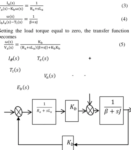
Taking the Laplace Transform of (1) and (2), one gets (3) and (4) respectively as follows.
(3)
(4) Setting the load torque equal to zero, the transfer function becomes
(5)
Fig. 2.DC motor transfer function block diagram model
3.2
Dc Motor Parameter Identification
In DC motor parameters to be identified are armature resistance, armature inductance, back emf constant, inertia and the coefficient of viscous friction [28].
3.2.1
Armature resistance
To determine the armature resistance of a DC motor, block its rotor so that it cannot turn and apply a small dc voltage to the armature terminals. Adjust that voltage until the current flowing in the armature is equal to the rated armature current of the machine. The ratio of the applied voltage to the resulting armature current flow is [29], [30].
3.2.2
Armature inductance
To measure the armature inductance, measuring and recording instantaneous or real-time changes is needed. This could be done using multimeter or oscilloscope. To do this measurement, a fixed voltage is supplied to a blocked DC motor. Back emf is zero since there is no rotor rotation [31].So the solution of (1) becomes
(6)
τ is the time constant and equal to , and is the steady
state current equal to ,and is the applied test voltage.
If the time when the current rises to 63.2% of Ia is measured to be τ, then La is calculated as
(7)
3.2.3
Back emf constant
To find the back emf constant, use (1) at steady state DC voltage input [28],[30]. At steady state the differentiation of the current is zero. So the equation becomes
(8)
By giving a DC voltage supply and measuring the steady state current and speed in rad/s, one can use (8) to identify the back emf constant of the motor which is equal to the torque constant if SI units are use.
3.2.4
Viscous friction constant
To find the viscous friction constant, (3) is used. By making the load torque zero, the steady state equation of (3) becomes [28]
(9)
3.2.5
Moment of inertia
To get the moment of inertia, run the motor to some final constant speed, , at no load. Then disconnect the armature supply voltage. The armature current will be zero. Then the solution of (2) becomes [28]
(10)
τ is the time constant and equal to , and is the time when the voltage is disconnected.
So, the moment of inertia is obtained from (11) as follows.
(11) Where is the time when the speed drops to 36.8% of
- -
-
[image:2.595.57.283.476.735.2]3.3
The PI Controller
The analog time PI controller [2] is
(12)
The discrete PI controller is obtained using trapezoidal rule as follows
(13) Where Kp is the proportional gain, KI is the integral gain and Ts is the sampling time.
The difference equation of the PI controller is
(14)
Where u(k) is the control input and e(k) is the error.PROTEUS VIRTUAL SYSTEM MODELLING (VSM)
3.4
Dc Motor Model in Proteus
[image:3.595.353.504.115.253.2]There are different DC motor models in Proteus (VSM). DC Motor model with inertia, loading and position encode is suitable for speed control application.
Fig. 3.DC motor model used in the simulation
3.5
Speed Measurement
By counting the pulses of the position encoder within a specified time, we can measure the speed of the motor. I used the duration of a single pulse of the encoder. The speed of the motor is calculated as
(15) Where is the speed in rpm, and T is the duration of one pulse of the encoder in sec, and is the number of pulses per revolution of the encoder.
3.6
Motor Drive Unit
L298 H-bridge driver IC is used in this simulation.L298 is a monolithic with 15 pins. It is a high voltage, high current and four-channel driver. L298 can control the motor circuit directly, and isolation is not required. Diodes are used in the driver circuit to protect the freewheeling L298 chip [34].
3.7
Arduino Microcontroller
The arduino microcontroller is to implement the controller and send the speed to MATLAB by serial communication.
4.
IMPLEMENTATION OF CLOSED
LOOP SYSTEM IN PROTEUS
4.1
The Dynamic Model Used
Some parameters of the motor are explicitly available on Proteus. The remaining ones can be obtained using the
[image:3.595.53.283.326.452.2]methods stated above. The time is taken as the simulation time of Proteus.
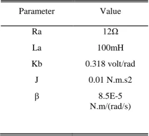
Table I Motor Parameter Values
Parameter Value
Ra 12Ω
La 100mH
Kb 0.318 volt/rad
J 0.01 N.m.s2 8.5E-5
N.m/(rad/s)
The speed used in this simulation is in rpm. So the following can be used to convert the rad/s speed to rpm.
(16) The motor speed is controlled using PWM. The Arduino microcontroller duty ratio range is from 0 to 255.The zero duty ratio corresponds to zero armature voltage and the 255 duty ratio corresponds to 12V armature voltage. So, the motor armature voltage is related to the duty ratio output of the microcontroller using (17) as follows.
(17) Where d is the duty ratio between 0 and 255.
4.1.1
Transfer function
Substituting (16) and (17) into (5), and using the parameters of the motor, the transfer function becomes
(18) Form the transfer function, it can be seen that it is a type zero. That means it doesn’t have a pole at the origin or an integrator.
4.1.2
PI controller
Kp = 3, Ki = 10 are arbitrarily taken for the PI controller. The control input to the motor is the duty ratio. So, substituting these values in to (14), the difference equation is
(19)
4.2
Programming the Arduino
Arduino code is written in C using the open source IDE. The important commands used in program are digital Write (pin,HIGH), analog Write (pin,value), analog Read (pin). Timer interrupt function is used to secure the sampling time and external interrupt function is used to measure the speed by counting the speed encoder pulses.
4.2.1
Sampling time
4.2.2
Speed measurement
The speed measurement is using external interrupt of arduino and the micros() function. The encoder pulses are input to the external interrupt of arduino and the micros() function is used to measure the period of these pulses.32pulses per revolution speed encoder is used for speed measurement for this simulation. So using (15) the speed measurement code inside the external interrupt service routine is
if(pulse_rise=1) t1=micros();
if pulse_rise=2){ t2=micros();
rpm=1000000*60/(32*(t2-t1));
pulse_rise=0 ;}
4.2.3
Control algorithm implementation
The implementation the PI controller in (19) using Arduino code is
float e=0,e_1=0,d=0,d_1=0;
void loop(){
d=d_1+(kp+KI*Ts/2)e+( KI*Ts/2-Kp)e_1;
analogWrite(PWM_pin,d);
e_1=e;
d_1=d;}
5.
MATLAB PROGRAM
The arduino microcontroller in proteus sends the speed of the motor to MATLAB via virtual serial port. Then MATLAB plots the response. Vertual COM ports are used for serial interfacing.
6.
SIMULATION OF THE SYSTEM
[image:4.595.336.520.78.230.2]In this section, the effects of proportional gain, integral gain and sampling time are simulated. For all cases the reference speed is 100rpm and the motor is at minimum load 1% of maximum torque according to Proteus.
Fig. 4. The overall simulation setup
6.1
Proportional Action
[image:4.595.338.517.312.455.2]For type zero system, when only proportional controller is used, the error between the reference input and the output is different from zero.
Fig. 5. Speed response for Kp = 3, KI = 0, Ts = 0.03sec
[image:4.595.324.523.474.654.2]As the proportional gain increases, the steady state error decreases, the speed of response increases but the response will have larger transient overshoot and more oscillation [2], [36], [37]. Fig (5) and fig (6) show the effect of a proportional controller.
Fig. 6.Speed response for Kp = 50, KI = 0, Ts = 0.03sec
6.2
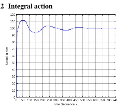
Integral action
Fig. 7. Speed response for Kp = 3, KI = 10, Ts = 0.03sec
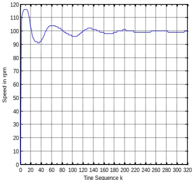
The main function of integral action is to make the steady state error zero. The response is faster for larger integral gain and it is also more oscillatory [2], [36], and [37].Fig (7) and fig (8) show the effect of integrator gain.
0 30 60 90 120 150 180 210 240 270 300 330 360 390 420 450 480 0
10 20 30 40 50 60 70 80 90 100
X: 421 Y: 88
Time Sequence k
S
p
e
e
d
i
n
r
p
m
0 10 20 30 40 50 60 70 80 90 100 110 0
10 20 30 40 50 60 70 80 90 100 110 120
X: 31 Y: 99
Time sequence k
S
p
e
e
d
i
n
r
p
m
0 50 100 150 200 250 300 350 400 450 500 550 600 650 700 746 0
10 20 30 40 50 60 70 80 90 100 110 120
Time Sequence k
S
p
e
e
d
i
n
r
p
[image:4.595.58.283.486.658.2]Fig. 8. Speed response for Kp = 3, KI = 15, Ts = 0.03sec
6.3
Effect of sampling time
One of the most important aspects of digital control is the sampling time. It affects the stability of the system. An increase in sampling time decreases the damping and increases the over shoot of the response [1], [2].Fig (7) and fig (9) show the effect of sampling time.
Fig. 9. speed response for Kp = 3, KI = 10, Ts = 0.1sec
7.
STUDENTS’ FEEDBACK
The simulation has been used to teach senior students at Addis Ababa University Institute of Technology for two semesters for the course ECEG-4606 Digital Control Systems. From the preliminary study using randomly taken 17 students concerning their feeling, 14 responded it was useful in understanding the concepts of the course and 13 students
8.
CONCLUSION
This paper has shown the way, how to teach the fundamentals of digital control without using hardwares. It shows that the simulation in Proteus VSM lab is very good and very easy way to teach the principles and implementations of digital control systems. The codes written and the setup in proteus can directly be used for hardware implementations. Protues VSM lab avoids the repeated cost due to repeated faults of hardwares. In this simulation setup ,PI controller is designed and used to show how to teach digital control principles ,but it can also be used with state feedback control or any other type of control like PID, phase lag, phase lead and phase lead-lag.
9.
REFERENCES
[1] M.Sam Fadali, Digital Control Engineering Analysis and Design, Elsevier Inc. Burlington, 2009
[2] Gene F. Franklin ,J.David Powell,and Michael Workman, Digital Control of Dynamic Systems, 3rd ed., Elias-Kagle-Press, USA, 2006
[3] Constantine H.Houpis and Gray B.Lamont, Digital Control Systems Theory Hardware Software, 2nd ed., McGraw-Hill Inc.1992
[4] Gene F. Franklin, and J. David Powell, “Digital control laboratory courses,” IEEE Control Systems Magazine, April 1989 .pp.10-13
[5] R.Krishnan, Electric Motor Drives Modeling Analysis and Control, Prentice Hall Inc, 2001
[6] Ali Bekir Yildiz , “Electrical equivalent circuit based modeling and analysis of direct current motors,” Electrical Power and Energy Systems,” vol. 43, Elsevier Ltd., 2012 .pp.1043–1047.
[7] Dogan Ibrahim, Microcontroller Based Applied Digital Control, John Wiley & Sons Ltd., Chichester ,2006
[8] Pratap Vikhe, Neelam Punjabi, and Chandrakant Kadu, ”Real time DC motor speed control using PID controller in LabVIEW,” International Journal of Advanced Research in Electrical Electronics and Instrumentation Engineering, Vol. 3, Issue 9, September 2014 ,pp. 12162-12167.
[9] Y.S.E.Ali, S.B.M.Noor, S.M.Bashi, and M.K.Hassan,”Microcontroller performance for DC motor speed control system,” IEEE, National Power and Energy Conference (PECon) Proceedings, Bangi, Malaysia, 2003, pp.104-109.
[10] S.M.Rangdal, and G.P.Jain, ”Speed control of DC motor using microcontroller,” International Journal of Advanced Technology in Engineering and Science, Volume 02, Issue 12, December 2014,pp. 482-489.
[11] Reetam Mondal, Arumay Mukhopadhyay, and Debdoot Basak, ”Embedded system of DC motor closed loop speed control based on 8051 microcontroller,” First International Conference on Computational Intelligence Modeling Techniques and Applications (CIMTA), Procedia Technology, vol.10,2013, pp.840 – 848.
[12] Panduranga Talavaru, Nagaraj Naik R, and V. Kishore Kumar Reddy V,”Microcontroller based closed loop speed and position control of DC motor,” International Journal of Engineering and Advanced Technology, Vol.3, Issue-5, June 2014 ,pp.280-285.
[13] Payal P.Raval, and C.R.mehta, ”Modeling simulation and implementation of speed control of DC motor using PIC 16F877A,” International Journal of Emerging Technology and Advanced Engineering, Vol.2, Issue 3, March 2012, pp. 146-151
[14] Bo Su, and Li Wang,”Application of proteus virtual system modelling (VSM) in teaching of microcontroller,” IEEE, International Conference on E-Health Networking Digital Ecosystems and Technologies, 2010, pp. 375-378.
[15] Heribertus Himawan, Catur Supriyanto, and Adrin Thamrin, ”Design of prepaid energy meter based on
0 50 100 150 200 250 300 350 400 450 500 550 600 650 700 750 800 0
10 20 30 40 50 60 70 80 90 100 110 120
Time Sequence k
S
p
e
e
d
i
n
r
p
m
0 20 40 60 80 100 120 140 160 180 200 220 240 260 280 300 320 0
10 20 30 40 50 60 70 80 90 100 110 120
Tine Sequence k
S
p
e
e
d
i
n
r
p
[image:5.595.70.263.330.510.2]PROTEUS,” IEEE, 2nd Int. Conference on Information Technology Computer and Electrical Engineering (ICITACEE) Proc., Indonesia, October 2015, pp. 239- 243 .
[16]Mohamad Nasrul Abdul Satar, and Dahaman Ishak (2011, May),”Application of proteus VSM in modelling brushless DC motor drives,” IEEE, 4th International Conference on Mechatronics (ICOM), Kuala Lumpur, Malaysia , May 2011.
[17]T.K.Sethuramalingam,and
M.Karthighairasan,”Automatic gas valve control system using arduino hardware,” Bonfring International Journal of Power Systems and Integrated Circuits, Vol. 2, No. 3, September 2012, pp.18-21.
[18]Akram Syed Ali, Zachary Zanzinger, Deion Debose, and Brent Stephens,” Open source building science sensors (OSBSS): a low-cost arduino-based platform for long-term indoor environmental data collection,” Building and Environment,vol.100, 2016 ,pp.114-126
[19]Gianluca Barbon, Michael Margolis, Filippo Palumbo, Franco Raimondi , and Nick Weldin, “Taking arduino to the internet of things: the ASIP programming model,” Computer Communications,vol.000,2016,pp.1-13
[20]Neerparaj Rai, and Bijay Rai,”Neural network based closed loop speed control of DC motor using arduino uno,” International Journal of Engineering Trends and Technology, Vol.4, Issue2.2013, pp. 137-140.
[21]Gerald W. Recktenwald and David E. Hall (2011),”Using arduino as a platform for programming, design and measurement in a freshman engineering course,” American Society for Engineering Education, 2011.
[22]Karthik Balasubramanian, Arokkia Jerald Praveen.D , Aswin Chandrasekaran, Nawin Pranav.M.V, and Kiran.R, ”Efficient mechanisms using arduino to control robots,” International Journal of Innovative Research in Electrical Electronics Instrumentation and Control engineering, Vol. 2, Issue 1.January 2014, pp. 562- 568.
[23]Y. V. Niranjan Kumar, P. Hima Bindu, A. Divya Sneha, and A. Sravani, ”A novel implementation of phase control technique for speed control of induction motor using arduino,” International Journal of Emerging Technology and Advanced Engineering, Volume 3, Issue 4, April 2013 , pp 469- 473.
[24]Vishnu V S, Aneesa K A, Arun Lal, and Absal Nabi,”Real time DC motor speed control using PID in LabVIEW with arduino,” Imperial Journal of Interdisciplinary Research (IJIR), Vol.2, Issue-5, 2016, pp. 1757- 1759.
[25]Nawi Berahim, Sulaini Besar, Mohd Zain Abdul Rahim, Shamsul Aizam Zulkifli, and Zairi Ismael Rizman, ”PID voltage control for DC motor using MATLAB simulink and arduino microcontroller,” Journal of Applied Environmental and Biological Sciences, Vol.5(9),2015, pp.661-731.
[26]Vijaya KK, and Surender S (2016),”Industry monitoring
robot using arduino uno with Matlab interface,” Advances in Robot & Automation, Vol.5, Issue 2,2016,pp.1-3
[27] Raquib Buksh, Soumyajit Routh, Parthib Mitra, Subhajit Banik, Abhishek Mallik, and Sauvik Das Gupta ,”Implementation of MA TLAB based object detection technique on arduino board and iROBOT CREATE,” International Journal of Scientific and Research Publications, Vol. 4, Issue 1, January 2014,pp.1-5
[28] C.Ganesh, B.Abhi, V.P.Anand, S.Aravind, R.Nandhini, and S.K.Patnaik,”DC position control system-determination of parameters and significance on system dynamics,” Proc. of Int. Conf. on Advances in Electrical & Electronics, 2011, pp.75-79.
[29] Stephen J. Chapman ,Electric Machinery Fundamentals,4th ed., McGraw-Hil, New York,2005
[30] Samer S. Saab, and Raed Abi Kaed-Bey,”Parameter identification of a DC motor: an experimental approach,” 8th IEEE International Conference on Electronics Circuits and Systems (ICECS 2001), September 2001, pp. 981-984.
[31] P. Wolm, X.Q. Chen, J.G. Chase, W. Pettigrew, and C.E. Hann, “Analysis of a PM DC motor model for application in feedback design for electric powered mobility vehicles,” 15th International Conference on Mechatronics and Machine Vision in Practice, December 2008.
[32] Prithviraj R. Shetti, and Ashok G. Mangave, ”DC motor speed control with feedback monitor based on C# application,” International Journal of Research in Engineering and Technology, Vol.03, Issue 03, March 2014, pp. 398- 401.
[33] Xu Xiumei, and Pan Jinfeng, ”The simulation of temperature and humidity control system based on PROTEUS,” IEEE, International Conference on Mechatronic Science Electric Engineering and Computer, Jilin, China, August 2011, pp. 1896- 1898
[34] Jie Sun, and Qinfang Sun ,”Design and Simulation of PWM DC Motor Speed Regulator Based on Proteus,” IEEE, International Conference on Fluid Power and Mechatronics, August 2015, pp.1210-1213
[35] Alok Mukherjee, Susanta Ray, and Arabinda Das, ” Development of microcontroller based speed control scheme of BLDC motor using proteus VSM software,” International Journal of Electronics and Electrical Engineering, Vol. 2, No. 1, March 2014, pp.1-7
[36] Karl J.Astrom, and Tore Hagglund, PID Controllers; Theory, Design and Tuning, 2nd ed, USA, 1995.
[37] Chi-Tsong Chen, Analog and Digital Control System Design Transfer-function,State-space and Algebraic Methods , Saubders College Publishing.