An Expert System for Design of Blanking Dies for
Sheet Metal Operations
S. Kumar, R. Singh, and G.S. Sekhon
Abstract - This paper describes an expert system developed for assisting die designers for design of blanking dies for sheet metal operations. The production rule-based expert system approach is utilized for development of the system. The proposed system labelled as INTBDIE is organized in form of twelve modules. Modules are coded in AutoLISP language and designed to be loaded into the prompt area of AutoCAD. For consultation, the user loads the system into the prompt area of AutoCAD. The proposed system generates friendly prompt eliciting from the user for data pertaining to the job. The recommendations imparted by the system for design of blanking die are automatically stored in various output data files which are further utilized for automatic modelling of die components and die assembly. This arrangement facilitates interfacing of design with drafting and can be operated on a PC/AT. The knowledge base of the proposed system can be modified depending upon the capabilities of a specific shop floor. As the system can be implemented on a PC having AutoCAD software, therefore its low cost of implementation makes it affordable for small and medium-sized stamping industries.
Index Terms—Blanking die, Expert system, Sheet metal operations, Stamping industries.
I. INTRODUCTION
The process of design and modelling of blanking die for sheet metal operations is quite systematic and involves various activities such as checking of part design features from manufacturability point of view, choice of manufacturing operations, selection of the type of die, selection of the press machine and selection of the dimensions of the die components. This process remains even today highly complex and time-consuming [1]. This is on account of the fact that the die designer is called upon to effect trade-offs between a numbers of mutually conflicting factors at initial stages of
Manuscript received May 10, 2008.
S. Kumar is with the Department of Mechanical Engineering, Sardar Vallabhbhai National Institute of Technology, Surat, Gujarat, India (Phone:+91-2612201697, e-mail: [email protected])
R. Singh is with the Department of Mechanical Engineering, D.C.R. University of Science & Technology, Murthal, Haryana, India (e-mail: [email protected])
G. S. Sekhon is retired from the Department of Applied Mechanics, Indian Institute of Technology, Delhi-110016, India (e-mail: [email protected])
design. Indeed many practitioners in industry believe that the art of die design can be mastered only through long years of experience. Traditional methods of design of blanking die for sheet metal operations involve numerous calculations and decisions which have to be made on the basis of experience and practice codes without the computer aids [2]. A die designer may have to spend many hours consulting hand books, going through empirical formulae, perusing tabulated and graphical information, and making calculations before arriving at workable designs. These activities are tedious and time consuming, and often do not yield optimum results. In recent years the computer aided procedures [1], [3]-[9] are being increasingly utilized to ameliorate the above difficulties. But there is not a single system which is capable to accomplish the complete design process of blanking die. Commercially available CAD/CAM systems are providing some assistance in drafting and analysis in die design process, but human expertise is still needed to arrive at the final design [10]. Also, the high cost associated with setting up such systems is quite often beyond the reach of small and medium sized sheet metal industries, especially in developing countries. There exists therefore, the need of developing an expert system for design of the blanking die. The system should be capable of providing expert advices to the planners of sheet metal operations especially one employed in the small scale stamping industries.
The specific objective of the present work is the development of an expert system for assisting the die designer for designing and modelling of blanking die. The production rule-based expert system approach is utilized for development of the proposed system. The remaining of this paper is organized as follows: Section 2 presents the procedure for development of the system. Section 3 gives the description of the proposed expert system. Section 4 demonstrates the usefulness of the proposed system using an industrial component. The last section gives conclusion of this paper.
II. PROCEDURE FOR DEVELOPMENT OF THE
PROPOSED SYSTEM
description of procedural steps [11] used for development of each module is given as under.
A. Collection of information for design of blanking die Information for design of blanking die were collected from a variety of sources including die design handbooks, industrial brochures, monographs, research journals, experienced die designers and shop floor engineers. The process of knowledge acquisition from experienced die designers involves presenting a few typical problems of blanking to the expert(s) and letting the expert(s) talk through the solution. During the verbal analysis, the expert(s) may be questioned / interrupted to explain why a particular decision was reached. Knowledge may be acquired from domain experts by holding discussions on typical problems pertaining to the die design and letting the experts talk about the approach, formulae and thumb-rules relied upon by them. They may be asked as to how and why a particular decision can be reached. This is to identify the parameters influencing particular decision.
B. Framing of production rules for each module of the proposed system
The production rule-based system is the earlier and more popular approach to represent analytical, heuristic or experience-based knowledge. Heuristic knowledge acquired for each module of the system INBDIE was framed into the production rules of IF (action) - THEN (conclusion) variety.
C. Verification of production rules
The production rules framed for an expert system must be verified from a team of domain expertsby presenting them IF-condition of the production rules and then matching their recommendations with the THEN-action part of rules. The production rules framed for the proposed system were properly verified from a team of experienced die designers.
D. Encoding of production rules for each module of proposed system
LISP and PROLOG are widely used for constructing expert systems. But the user of these languages encounters difficulties when handling design problems involving graphical information. For this reason AutoCAD and AutoLISP have found greater acceptance in design and manufacturing, evaluation of design alternatives, and creation of drawings. Expert system applications involving graphical data can be built by combining AutoLISP and AutoCAD [12]. For this reason, the present system makes use of AutoLISP and AutoCAD facilities for encoding the production rules of each module.
E. Preparation of user interface
The purpose of user interface is two fold. It enables the user
to input the essential job related data to each module and it displays the optimal design choices for the user's benefit. This is achieved by making the interface flash prompts at appropriate stages during a consultation inviting the user to input data items. It also displays messages or advice on the computer screen at appropriate times. The user is also guided in a friendly manner throughout the consultation on how to proceed further at each different stage. The user initially loads the proposed expert system by using the command (Load "A: INTBDIE.LSP") in prompt area of AutoCAD. The program, after compilation, is ready for serving the user.
III. DESCRIPTION OF THE PROPOSED EXPERT SYSTEM
The proposed system INTBDIE is organized into twelve modules namely PARTDGN, PROPLAN, TLDGN, PRESS, DIE, DILACL, CLAA1, STRIPPER, PUNCH, DSSEL, DISETDIM, and FASTNER. A brief description of each module is given as under.
A. Module PARTDGN
The first module labelled as PARTDGN is developed for assisting the user for carrying out the design check on sheet metal parts. The module incorporates an interface for displaying friendly prompts to guide the user during a consultation session. The input data supplied by the user is also stored in a file, called as PART.DAT for use in subsequent modules.
B. Module PROPLAN
The module PROPLAN is developed for selection of sheet metal operations. The decision of selection of suitable operations for manufacturing a specified sheet metal component depends on a number of factors such as part design, sheet material, production quantity, quality specifications, installed facilities, and available dies and tools etc. The module PROPLAN is designed to call the data file PART.DAT. During a consultation session, the user is also invited by the module to feed inputs necessary for making the selection of the manufacturing operations for a given component. The data related to the kind of sheet operation, generated during execution is appended in the file PART.DAT for further use in subsequent modules.
C. Module TLDGN
This module is designed for assisting the user in the selection of suitable type of die for a given job. Altogether 55 production rules were framed for this module.
D. Module PRESS
the minimum force required for carrying the needed sheet metal operation for the benefit of the user and identifies the alternative machines which can be used for the job. Afterwards the user is invited to supply data regarding fixed and operating costs for each candidate press machine in turn. The production cost per unit is computed and retained in memory for as many candidate machines as required. In the end, the module identifies the press for which the cost per unit is likely to be the smallest.
E. Module DIE
This module is developed to assist the user to select correct size of the die block. Parameters affecting the size of die block include sheet thickness, total blank perimeter, contour width, contour length and direction of the sharp edge of strip and the die material. The width of strip is stored in file SSLW.DAT. The module DIE has more than 40 production rules coded in AutoLISP. The recommended size of die block is automatically stored in a file labelled as DIE.DAT which is further used for modelling of die components and die assembly.
F. Modules DILACL AND CLAA1
The Modules DILACL and CLAA1 are developed for selection of die-land, die-angle and cutting clearances. The cutting clearance per side depends upon the thickness, shearing strength and hardness of the sheet material, job accuracy and the type of operation. The recommendations imparted by these modules are automatically stored in a file labelled as CLAA.DAT which may be recalled during the execution of subsequent modules.
G. Module STRIPPER
This module is constructed for assisting the user in the selection of stripper details. Type and size of stripper depends upon component thickness, job accuracy and the kind of operation. The dimensional data recommended by the module STRIPPER is stored automatically in a data file named as STRIPPER.DAT for its further use in the automatic modelling of stripper plate.
H. Module PUNCH
The module PUNCH is developed for selection of the type and size of punches. It also assists in the selection of proper size of punch plate and back up plate. The expert advices imparted by this module are automatically stored in an output data file labelled as PUNCH.DAT for its further use in the automatic modelling of punch, punch plate and back up plate.
I.
Modules DSSEL and DISETDIMThe modules DSSEL and DISETDIM are framed for assisting the user for selection of type of die-set and its size. Selection of the type of die-set depends upon the type of sheet
metal operation, part quantity and job accuracy. The size of the die-set depends upon the size of the die and its placement in the die-set. For automating the design process, the type of die-set as recommended by the module DSSEL is automatically stored in a file labelled as DSSEL.DAT. The dimensional data namely size of bottom and top bolster of die-set, diameters of guide pillars and guide bushes as recommended by the another module DIESETDIM are automatically stored in a file labelled as DISETDIM.DAT for its further use in modelling of die components and die assembly.
J. Module FASTNER
The module FASTNER is developed for selection of number and size of fasteners (bolts and dowels). The module automatically stores the recommended diameter of fasteners in a file named as FASTNER.DAT for its further use in modelling of die components and die assembly.
IV. ILLUSTRATIVE EXAMPLE
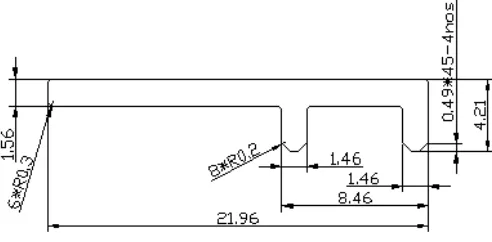
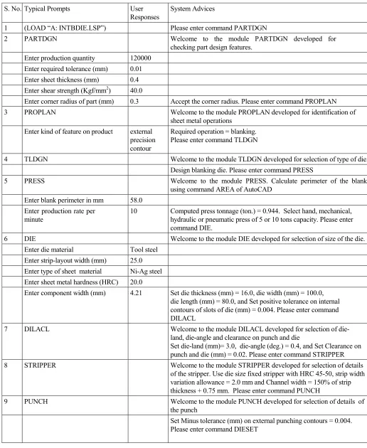
The proposed system INTBDIE has been tested for wide variety of sheet metal parts for design of blanking die. A sample of typical prompts, user responses and advices generated by the system for one example component (Fig. 1) are depicted through Table 1. The different modules of the proposed system render enough advices and provide sufficient design data for modelling of blanking die. The system also generates drawings of die components and die assembly automatically in the drawing editor of AutoCAD. Orthographic views of the lower portion of assembled blanking die automatically generated by the proposed system are shown in Fig. 2. The recommendations obtained by the proposed system and drawings generated by the system for example component were found to be reasonably close to those actually used in industry namely M/S Indian Telephone Industries, Rae-Barely, India for the example component.
[image:3.595.313.559.566.687.2]Table 1. Typical prompts, user responses and expert advices imparted by the system for example component
S. No. Typical Prompts User
Responses
System Advices
1 (LOAD “A: INTBDIE.LSP”) Please enter command PARTDGN
2 PARTDGN Welcome to the module PARTDGN developed for
checking part design features. Enter production quantity 120000
Enter required tolerance (mm) 0.01 Enter sheet thickness (mm) 0.4 Enter shear strength (Kgf/mm2) 40.0
Enter corner radius of part (mm) 0.3 Accept the corner radius. Please enter command PROPLAN
3 PROPLAN Welcome to the module PROPLAN developed for identification of
sheet metal operations Enter kind of feature on product external
precision contour
Required operation = blanking. Please enter command TLDGN
4 TLDGN Welcome to the module TLDGN developed for selection of type of die.
Design blanking die. Please enter command PRESS
5 PRESS Welcome to the module PRESS. Calculate perimeter of the blank
using command AREA of AutoCAD Enter blank perimeter in mm 58.0
Enter production rate per minute
10 Computed press tonnage (ton.) = 0.944. Select hand, mechanical, hydraulic or pneumatic press of 5 or 10 tons capacity. Please enter command DIE.
6 DIE Welcome to the module DIE developed for selection of size of the die.
Enter die material Tool steel
Enter strip-layout width (mm) 25.0 Enter type of sheet material Ni-Ag steel Enter sheet metal hardness (HRC) 20.0
Enter component width (mm) 4.21 Set die thickness (mm) = 16.0, die width (mm) = 100.0, die length (mm) = 80.0, and Set positive tolerance on internal contours of slots of die (mm) = 0.004. Please enter command DILACL
7 DILACL Welcome to the module DILACL developed for selection of die-
land, die-angle and clearance on punch and die
Set die-land (mm)= 3.0, die-angle (deg.) = 0.4, and Set Clearance on punch and die (mm) = 0.02. Please enter command STRIPPER
8 STRIPPER Welcome to the module STRIPPER developed for selection of details
of the stripper. Use die size fixed stripper with HRC 45-50, strip width variation allowance = 2.0 mm and Channel width = 150% of strip thickness + 0.75 mm. Please enter command PUNCH
9 PUNCH Welcome to the module PUNCH developed for selection of details of
the punch
10 DIESET Welcome to the module DIESET developed for selection of the kind of die-set and its dimensions.
Use die-set of 2 flat bushings on top bolster and 2 guide posts on bottom bolster, and Place die perpendicular in rear pillar (diameter 19 mm) die set having length, width and thickness of bottom bolster (mm) as 150, 145 and 39. Please enter command FASTNER.
11 FASTNER Use 4 Allen bolts M 8 and 2 dowels of diameter = 10 mm
V. CONCLUSION
The proposed system has been developed using production rule-based expert system approach of artificial intelligence. Knowledge for the design of blanking die obtained from die designers, hand books, catalogues and brochures has been analysed, tabulated and incorporated into production rules of IF-THEN variety. These rules were coded in AutoLISP language. The system has been organized into twelve modules. Modules are user interactive and designed to be loaded in to the prompt area of AutoCAD. System modules are capable to impart expert advices on checking manufacturability of part, selection of press machine and selection of die components. Expert advices imparted by the system modules are automatically stored in various output data files, which are utilized for automatic modelling of blanking die. The system has been tested for a wide variety of industrial sheet metal parts. Recommendations imparted and drawings generated by the system were found to be reasonable and very similar to those actually used in sheet metal industries. The system is capable of accomplishing the tedious and time-consuming task of blanking die design in a very short time period. As the system can be implemented on a PC having AutoCAD software, therefore it is a low cost alternative for process planners and die designers working in small and medium sized stamping industries.
REFERENCES
[1] R. Hambli, “BLANKSOFT: A code for sheet metal blanking processes optimization”, Journal of Material Processing Technology, vol. 141, 2003, pp. 234-242.
[2] S. J. Lee, K. S. Park, J. H. Kim, and S. S. Lee, S.-S. (2007). “Development of a design supporting system for press die of automobile panels”, Proc. 10th International Conference, CSCWD 2006, Nanjing, China, May 3-5, 2006, pp. 207-216, Springer-Verlag, Berlin, Heidelberg, ISBN: 978-3-540-72862-7, 2007. [3] R. V. Rao, “Evaluation of metal stamping layouts using an analytic
hierarchy process method”, Journal of Materials Processing Technology, vol. 152, 2004, pp. 71–76.
[4] F. Kroupi, A heuristic based approach to press tool design assembly, PhD Thesis, University of Birmingham, 1989.
[5] Y. K. D. V. Prasad, Some studies on problems associated with automated design of cutting dies for sheet metal, Ph. D Thesis, Dept. of Mechanical Engg., Indian Institute of Technology, Bombay, 1992. [6] B. T. Cheok, and K. Y. Foong, “An intelligent planning aid for design
of progressive dies”, Proc. Instn. Mech. Engrs., Part B: Journal of Engineering Manufacture, vol. 210, 1995, pp. 25- 35.
[7] R. Singh, and G. S. Sekhon, “A computerized diagraph and matrix approach for valuation of metal stamping layouts”, Journal of Material Processing Technology, vol. 59, 1996, pp. 285-293.
[8] R. Pilani, K. Narasimhan, S. K. Maiti, U. P. Singh, and P. P. Date, “A hybrid intelligent systems approach for die design in sheet metal forming”. Int. Journal of Advanced Manufacturing Technology, vol. 16, 2000, pp. 370-375.
[9] S. Kumar, R. Singh and G. S. Sekhon, “CCKBS: A component check knowledge-based system for assessing manufacturability of sheet metal parts”, Journal of Materials processing Technology, vol. 172, 2006, pp. 64–69.
[10] S. Kumar, and R. Singh, “Trends and developments in intelligent computer aided design of progressive dies”, Advanced Materials Research, vol. 6-8, 2005, pp. 241-248.
[11] S. Kumar, and R. Singh, “Developmental framework of KBS for engineering problems”, Proc. National Symposium on Power and Energy for Sustainable Growth, Institution of Engineers (India), Murthal, India, 2003, pp. 290-295.
[12] D. Jain, and L. M. Marry, “Combining expert system and CAD techniques”, Artificial Intelligence Developments and Application,