the gear design parameters on the contact stress and bending stress at tooth root.
II. GEOMETRY OF THE MODIFIED CURVILINEAR GEAR
The modified curvilinear gear was generated by a male fly cutter with a circular-arc normal section, and the generation process can be simulated by an imaginary rack cutter with circular-arc normal section. Figure 2 shows the normal section and the radius of the circular-arc is RP. The
application of fly cutters having a circular-arc curve rather than a straight edge in their normal sections will introduce a pre-designed transmission error when the modified curvilinear gear set is in the ideal meshing condition. In addition, the proposed curvilinear gear set are expected to have localized point contact in the central region of the tooth flank instead of line contact across the entire tooth flank.
Figure 2 depicts the circular-arc normal section with radius RP of the imaginary rack cutter used to generate the
gear. Figure 3 shows the formation of the three dimensional imaginary rack cutter P to generate the gear by moving its
normal section along a curve of radius Ep. The radius Ep
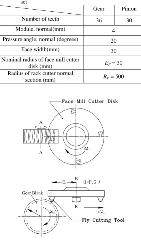
equals the nominal radius of the face mill cutter disk on which the fly cutters are assembled to generate the curvilinear gears, as indicated in Fig.1. Note that EP should
be the same for the mating pinion and gear to have proper meshing tooth traces. Figure 4 illustrates the relationships among the rack cutter axode and the corresponding generated gear axode. In Fig.4, cylinder of pitch radius r1 is
the gear axode. Plane
, which is tangent to the cylinder, represents the axode of the rack cutter P. The line oftangency of these axodes, I-I, represents the instantaneous axis of gear rotation. In the generating process, the rack cutter translates with distance r11 while the generated gear
rotates with an angle 1.
Based on the theory of gearing and the generation mechanism, the tooth surfaces of the modified curvilinear gear are represented by the following equations.
) sin (cos
sin
cos ( ) 1 1 1 1 1
1 ) (
1 x y r
x P c P c
,
) cos (sin cossin ( ) 1 1 1 1 1
1 ) (
1 x y r
y P
c P
c
,
(1)andz1zc(P)
,
, 0 sin cos cos ) sin (sin sin ) cos 1 ( sin cos ] 2 / ) cos (cos [ ) , , ( 1 1 1 1 P P P n P P P P P P P P n P P P P r R E S R f (2) where ) sin (sin ) ( n P P P c R
x
,
) cos 1 ( cos ] 2 / ) cos (cos [ ) ( P P P P n P P P
c R S E
y
,
(3)and P P P P n P P P
c R S E
z( )[ (cos cos ) /2]sin sin
where Pl P Pu , sin 1( /2 )
P
Pl W E
and ) 2 / ( sin1 P
Pu W E
.
The upper sign and lower sign represent the gear tooth surfaces generated by the left side and right side of the rack cutter P, respectively.
In addition, the unit normal vector of the modified curvilinear pinion tooth surface can be expressed as follows:
1 ) ( 1 ) (
1
cos
sin
P yc P
xc
x
n
n
n
, 1 ) ( 1 ) (1
sin
cos
P yc P
xc
y
n
n
n
, (4)and
n
z1
n
(zcP),where
P P
xc
n( ) sin
,
P P P ycn( ) cos cos
,
(5)and P P P
zc
n( ) cos
sin
.
The upper sign and lower sign represent the pinion tooth surfaces generated by the left side and right side of the rack cutter P, respectively.
III. FINITE ELEMENT CONTACT ANALYSIS
The developed mathematical models enable us to build the solid model of the proposed modified curvilinear gear set, as shown in Fig.5. Table 1 lists the major design parameters for this curvilinear gear set. Then a finite element model of the modified curvilinear gear set has been built and contact stress analysis has been performed based on the design parameters.
A. Finite Element Models
This study adopts the general-purpose FEA software, ABAQUS/Standard to evaluate the stress distribution of the proposed curvilinear gear set. A linear brick element, C3D8I, having eight nodes and six faces, is employed to discretize the geometric models of the pinion and the gear tooth surfaces. In general, a finite element (FE) model with a larger number of elements for FE stress analysis may lead to more accurate results. However, an FEA model of the whole gear drive is not preferred, especially considering the limit of computer memories and the need for saving computational time. This study establishes an FE model of one pair of contact teeth for the curvilinear gear set. Figure 6 displays the mesh system of the mating pinion and the gear. The regions where stress concentration may occur, such as the fillets and possible contact areas, are processed by a finer mesh. Hence, the mesh density of the middle sections of the gear tooth flanks is increased, as illustrated in Fig.6. In sum, 30658 elements and 35131 nodes are used for the pinion and the gear FE model.
software, a linear brick C3D8I element is chosen, and each node has three translational degrees of freedom (DOF) along the nodal x-, y- and z- directions. In this study, all the three DOF of the nodes located on the two lateral sides of the gear’s base are fixed, as depicted in Fig.6. On the other hand, rigid beam elements are applied to connect the nodes on the pinion’s bottom surface with those on the pinion’s rotational axis. Furthermore, the nodes on the pinion’s rotational axis are constrained such that the pinion can rotate only about its rotational axis. Consequently, the gear is statically fixed and a torque is applied at the pinion’s rotational axis to make the gear and pinion tooth surfaces contact with each other.
C. Preliminary Considerations and Assumptions In the FEA, a single pair of contact teeth is constructed to perform the stress analysis, as shown in Fig.6. The following assumptions have been made for the contact analysis: (1) The stress is in the elastic range of the material; (2) The material is isotropic; and (3) Heat generation due to friction and thermal stress are ignored.
Additionally, the master and slave surfaces are identified as the gear and the pinion tooth surfaces, respectively. During the contact process, the slave nodes cannot penetrate the master surface segments, but the nodes on the master surface may penetrate the slave surface segments. “Small sliding” is specified between the contact surfaces to save computational efforts. It is also assumed that the gear set are mesh under good lubrication, and thus the contact surface is frictionless. Table 1 summarized the design parameters of the proposed modified curvilinear gear set. In the following examples, a torque of 25 N-m was applied to the pinion’s axis.
IV. ILLUSTRATIVE EXAMPLES
Example 1: Contact Stress
According to the FE stress analysis simulation, Fig.7 illustrates the distribution of von-Mises stress on the pinion and gear tooth surfaces when the pinion’s rotational angle is 0o. The maximum stress occurs at the contact point located in the middle of the tooth flanks. Based on the FEA results, the maximum value of von-Mises stress is 404.6MPa on the pinion and 339.7MPa on the gear, respectively.
Example 2: Contact Stress under Different Design Parameters
According to the FEA results, Fig.8 and Fig.9 displays the maximum values of von-Mises stress on the pinion and gear under different design parameters of EP and RP, respectively.
According to Fig.8, when RP is fixed at 500mm, the
maximum von-Mises stress decreases as EP increases from
30mm to 90mm. On the other hand, Fig.9 reveals that when EP is fixed at 30mm, the maximum value of von-Mises
stress is almost the same under different values of RP.
Therefore, the influence of RP on the contact stress is
insignificant when compared with that of EP.
Recall that for the generation of the modified curvilinear gear, parameter RP indicates the radius of the rack cutter’s
normal section, while parameter EP denotes the nominal
radius of the face mill cutter disk, as shown in Fig.2 and Fig.3, respectively. Therefore, RP is related to the deviation
of the generated tooth profile from a standard involute curve. The deviation results in a pre-designed parabolic transmission error of this curvilinear gear set. On the other hand, EP affects the curvature along the curvilinear gear
tooth trace along the axial direction. The curvilinear tooth trace will approach to a straight line as spur gears as EP
increases to infinity. Recall that for a spur gear set, the contact pattern is line contact along the axial direction. Consequently, increasing the design parameter EP will
increase the contact area, and therefore will reduce the contact stress.
Example 3: Bending Stress
The bending stresses at the gear tooth fillet are determined at different pinion’s rotational angles according to the FEA results. The bending stress is calculated from the tooth fillet at the middle of the tooth flank, below the theoretical contact point which can be calculated from the tooth contact analysis. Accordingly, Figs. 10(a)-(c) demonstrate the stress distributions at the central cross-sections of the contacting pinion and the gear under three contact positions (1’= -10o, 0o, 10o), respectively. The contact point moves from the tooth root to the tooth addendum in the middle of the tooth flank as the pinion rotates. Moreover, the variation of the bending stress is small because the bending stress in the fillet is much smaller than the contact stress.
Generally, the bending stresses in the fillets of the two contacting tooth sides are considered tensile stresses, and those in the fillets of the opposite, unloaded tooth side, are considered compressive stresses. Figures 11 depict the tensile bending stresses on the gear and pinion fillets under different contact positions. The bending stress is designated as the von-Mises stress calculated at the fillet on the center of the tooth flank, as indicated in Fig.7. When 1’= -10o, as shown in Fig.10, the contact point is close to the pinion tooth root and the tensile bending stress is high due to stress concentration. On the other hand, at 1’= 10o, the contact position is near the addendum of the pinion, exerting a large bending moment and a high bending stress on the pinion’s tooth root. Therefore, the maximum tensile bending stresses under the two contact positions (1’= -10o and 1’= 10o) are higher than other positions. However, the average bending stress during the tooth meshing is 25MPa, and is low regarding the tooth strength.
V. CONCLUSIONS
In this study, finite element stress analysis was performed to explore the contact stress and the bending stress of one contacting tooth pair of modified curvilinear gears. The FE model of the modified curvilinear gear set was developed based on the developed geometrical models. The commercial FEA package, ABAQUS, was applied to evaluate the stress distribution on the tooth surfaces. The analysis results leads to the following conclusions:
2) Increasing EP results in an increase in the contact area
and a reduction in contact stress. Moreover, the effect of RP on the contact stress is less significant than the
influence of EP.
3) The maximum fillet stress occurs near the middle section of the tooth flank (below the contact points). And the tensile bending stresses at the central cross-sections of the pinion and gear under different contact positions were investigated.
4) The preliminary FEA including only one contact tooth pair enables us to calculate the contact and bending stresses of the modified curvilinear gears. This model can be extended further to investigate the load sharing and transmission errors under load of multiple contact tooth pairs in the future.
REFERENCES
[1] Liu, S. T., “Curvilinear Cylindrical Gears,” Gear Technology, pp.8-12, 1988.
[2] Dai, Y., Ariga, Y. and Nagata, S., “Study on a Cylindrical Gear with Curved Tooth Trace,” Tenth world congress on the theory of machine and mechanism, pp. 2337-2342, 1999.
[3] Tseng, R. T. and Tsay, C. B., “Mathematical Model and
Undercutting of Cylindrical Gears with Curvilinear Shaped Teeth,” Mechanism and Machine Theory, pp.1189-1202, 2001.
[4] Litvin, F. L., Theory of Gearing, NASA Publication RP-1212, Washington D. C., 1989a
[5] Tseng, R. T. and Tsay, C. B., “Contact Characteristics of Cylindrical Gears with Curvilinear Shaped Teeth,” Mechanism and Machine Theory, pp. 905-919, 2004.
[6] Litvin, F. L., Zhang, J., Handschuh, R. F. and Coy, J. J., “Topology of Modified Helical Gears,” Surface Topography, pp. 41-58, 1989b.
[7] Litvin, F. L., Gear Geometry and Applied Theory, Prentice-Hall, New Jersey , 1994a.
[8] Litvin, F. L., Chen, N. X., Hsiao, C. L. and Handschuh, R. F., “ Generation of Helical Gears with New Surfaces Topology by Application of CNC Machines,” Gear Technology, pp. 30-33, 1994b.
[9] Litvin, F. L., Chen, N. X., Lu, J. and Handschuh, R. F., “ Computerized Design and Generation of Low-Noise Helical Gears with Modified Surface Topology,” ASME Journal of Mechanical Design, Vol. 117, pp. 254-261, 1995.
[10] Litvin, F. L. and Kim, D. H., “Computerized Design, Generation and Simulation of Modified Involute Spur Gears with Localized Bearing Contact and Reduced Level of Transmission Errors,” ASME Journal of Mechanical Design, Vol. 119, pp. 96-100, 1997. [11] Zhang, Y. and Fang, Z., “Analysis of Transmission Errors Under
Load of Helical Gears with Modified Tooth Gears,” ASME Journal of Mechanical Design, Vol. 119, pp. 120-126, 1997.
[12] Chang, S. L., Tsay, C. B. and Tseng, C. H., “Kinematic
Optimization of a Modified Helical Gear Train,” ASME Journal of Mechanical Design, Vol. 119, pp. 307-314, 1997.
[13] Chen, Y. C. and Tsay, C. B., “Mathematical Model and
Undercutting Analysis of Modified Circular-Arc Helical Gears,” J. of the Chinese Society of Mechanical Engineering, Vol. 22, No.1, pp. 41-51, 2001.
[14] Chen, Y. C. and Tsay, C. B., “Tooth contact analysis and kinematic optimization of a modified helical gear pair with involute-teeth pinion and modified circular-arc-teeth gear,” J. of the Chinese Society of Mechanical Engineering, Vol. 21, No.6, pp. 537-547, 2000.
[15] Barone, S., Borgianni, L. and Forte, P., “Evaluation of effect of misalignment and Profile Modification in face gear drive by a finite element meshing simulation,” ASME Journal of Mechanical Design, vol. 126, pp. 916-924, 2004.
[16] Yang, S.C., “Study on an internal gear with asymmetric involute teeth,” Mechanism and Machine Theory, vol. 42, pp. 977-994, 2007. [17] Lin, T., Ou, H. and Li, R., “A finite element method for 3D static
and dynamic contact/impact analysis of gear drives,” Computer Methods in Applied Mechanics and Engineering, vol. 196, pp. 1716-1728, 2007.
[image:4.595.304.549.104.518.2][18] Chen, Y. C. and Tsay, C. B “Stress analysis of a helical gear set with localized bearing contact,” Finite Elements in Analysis and Design, Vol. 38, Issue 8, pp. 707-723, 2002.
Table 1 Design parameters of the modified curvilinear gear set
Gear Pinion
Number of teeth 36 30
Module, normal(mm) 4
Pressure angle, normal (degrees) 20
Face width(mm) 30
Nominal radius of face mill cutter
disk (mm) EP = 30
Radius of rack cutter normal
section (mm) RP = 500
A A
g
t
B
g
B
i
Gear Blank
r r
[image:4.595.334.521.273.509.2]E (i=P,G )
Fig.1 Schematic illustration of curvilinear gear generation by fly cutters
[image:4.595.324.531.585.726.2]Fig.3 Formation of three-dimensional rack cutter
PFig.4 Relationships among gear blank axode, and rack cutter axode during generation process
Fig.5 The solid model of the modified curvilinear gear set
Fig.6 Finite element model of the curvilinear gear set
(a)Pinion
(b)Gear
Fig.7 Stress distribution on the pinion and gear tooth surface (at ∅/
1=0o)
O
W
i
O
(i) c
Z(i)c
(i) r
C (i)
i
Yr
Y(i)
c (i)
Zr
t
X
Xc
(i) r (i)
W 2
(i)
Fig.8 The effects of the nominal radius of face mill cutter disk EP on the maximum value of contact stress.
Fig.9 The effects of the radius of rack cutter normal section RP on the maximum value of contact stress.
Fig.10 The stress distribution at the central cross-sections of the pinion and gear under different contact positions.