Abstract— The traditional manufacturing control systems are often lacking in terms of the capabilities of responsiveness, flexibility, robustness and re-configurability. To reduce cost and increase flexibility, a reconfigurable Component Based (CB) automation approach is proposed in this paper. The research work presented in this paper is focused on communicating embedded device based components using the application of Ethernet and Service-Oriented Architectures (SOAs). This approach has the potential to give comparatively increased flexibility, and lower costs to manage and redesign individual components in comparison with traditional automation systems. A novel implementation of Web Services (WS) enabled automation using a component-based design approach for distributed peer to peer automation systems is outlined in this paper.
Index Terms—Component Based Systems, Distributed Automation Systems, Reconfigurability, Assembly Automation, SOA and Web Services.
I. INTRODUCTION
In today’s progressively changing global market, customers demand low-volume, high-quality, customized products. These factors create the need for a short product lifecycles, development times, and production lead times; compared to traditional manufacturing paradigms [1, 2]. Therefore, to provide a solution to this problem, the manufacturing industries are rapidly adopting the concept of mass customization; and are looking forward modifying their manufacturing paradigms and systems toward more flexible, adaptive, responsive approaches to meet customer demands with improved efficiency. Such a manufacturing environment can be realized using the concept of an agile manufacturing framework; focusing on a wider perspective of integrating the business enterprise and the business architecture with the shop-floor automation systems during the product development process [3, 4]. In such a manufacturing system, the manufacturers distribute intelligence and decision making authority as close to the points of action, delivery and sales service as possible [5].
Manuscript received March 18, 2010.
Navjot Kaur is Research Student in Wolfson School of Mechanical & Manufacturing Engineering, Loughborough University, Loughborough LE11 3TU (phone: +44 (0)1509 227 545; e-mail: [email protected]).
Robert Harrison is Senior Lecturer with Wolfson School of Mechanical & Manufacturing Engineering, Loughborough University, Loughborough (e-mail: [email protected]).
Andrew West is Senior Lecturer with Wolfson School of Mechanical & Manufacturing Engineering, Loughborough University, Loughborough (e-mail: [email protected]).
Punnuluk Phaithoonbuathong is Research Associate with Wolfson School of Mechanical & Manufacturing Engineering, Loughborough University, Loughborough (e-mail: [email protected]).
In recent years, the utilization of Web Services, typically based on the use of Ethernet, in the control systems has become an emerging approach to reduce technological barriers between the shop-floor automation and Enterprise systems. Web Services are widely used as a communication link in Enterprise systems; thus, the integration of various applications especially in pervasive manufacturing environments can be made simpler and more cost effective. Therefore, this paper presents an implementation framework utilizing Web Services with a component-based design approach previously developed at Loughborough University [6, 7] on PLC-based control devices supported by Schneider Electric. The work extends the WS prototype of an industrial test rig demonstration system developed at Loughborough University to a feasible industrial design of a fully distributed control systems.
II. PRESENT STATE-OF-THE-ART
Initially, Web Services based manufacturing systems have been proposed and developed in the main to support remote HMI and system diagnostics functionality [9, 10]. However in recent years, a number of projects have proposed solutions based on an objected-oriented design framework to develop modular design software structures for manufacturing integration (e.g. OPC UA [8], ESPRIT III OSACA [9], and COMPAG [6]). The RIMACS consortium [10] initiated the implementation of a WS capability (enabled by Devices Profile for Web Services (DPWS)) on the target PLC based device control platform. An extensive pilot implementation of WS-based control of this type was implemented on the SOCRADES project where the authors were involved at Loughborough as a consortium member studying manufacturing automation. In this paper, related research work is focused on employing Schneider Electric’s Simple Terminal Blocks (STBs) as WS-based embedded distributed control devices. This work is a part of a research programme in progress in the Mechanical and Manufacturing Engineering Department of Loughborough University. The work is focused on the lifecycle support of distributed automation systems by replacing centralized PLC controllers with distributed control nodes and a component-based (CB) design approach, where the control functionality is embedded into the component modules.
III. COMPONENT BASED DESIGN FRAMEWORK To meet the challenges mentioned above in section I, a distributed automation system is required in which the control devices are interconnected with each other using WS interfaces (i.e. Device Profile for Web Services-DPWS)
Web Services - Based Control Devices for Future
Generation Distributed Automation Systems
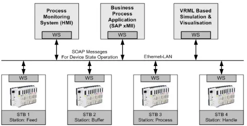
[11, 12]. The design and realization of such a system requires: a) Architecture, b) Controlling devices with I/O module for sensors and actuators, and c) Engineering tools for designing and implementing WS based architectures. The architecture of current research work is based on the component based design approach for the distributed automation system presented in [6]. A typical example of this approach is depicted in Figure 1; which is a Ford Festo test rig. This replicates functionality, typical in Ford powertrain assembly machines.
In Figure 1, to design a distributed control system using the CB approach, the architecture of the assembly machine system is categorized in a hierarchical structure: Machine-Stations-Components-Elements-Inputs/Output sensors. The machine system in Figure 1 comprises 4 stations (subsystems); including a hopper unit, buffering unit, processing index table unit, and handling arm unit, which are linked together via Ethernet communication systems to form the completed work process. These subsystems constitute various components; containing mechanical units, electrical units (sensors, actuator, I/O interface) and control software. In current research, the term “component” is defined as the constitution of: (1) a controller unit which includes network communication, hardware configuration, and control application, (2) electronic interface, and (3) physical inputs and outputs. Each station is controlled by a corresponding controller/control device (STB in current paper), which manipulates the actuators to achieve the assigned manufacturing tasks. The communication between controllers is achieved by network variable exchanges (i.e. state
information) over the Ethernet. In the CB design approach, the component functionalities are represented by the element’s state, behavior (i.e. control logic/state transitions), operations, and error information, which are encapsulated in each controller unit. Considering physical machine movement, a machine application is a combination and execution of these distributed components depending on the defined control logics including the component interaction (interlocking) design within the event-driven method. The control logics are encapsulated and exposed through WS interface of inter-connecting devices. The full details are presented in [13].
[image:2.595.132.467.431.666.2]In the CB design architecture, these components are pre-built with the required functional and integration capabilities to enable effective composition into instances of machines based on the required specification of machine end-users. To provide flexibility and reconfigurability, user applications are composed by a higher level engineering tool. In addition to the CB approach, the control system can be seen as a set of mechatronic components with each device responsible for a basic operation then the more complex manufacturing tasks can be created from the combination of basic components [7]. Therefore, the key task to realize such a modular system is the design of generic hardware and control software components that could be reconfigured to form new machine configurations to suit different production types. This architecture will be beneficial as it will help enabling efficient machine build and re-use of designs in order to optimize the machine’s lifecycle across supply chain partners.
Figure 1: Ford Festo rig layout: A distributed CB design of a powertrain assembly machine [13].
IV. THE AREA OF DEVELOPMENT AND NOVEL CONTRIBUTION
In the Festo test rig shown in Figure 1, web services are initially implemented on the Schneider Electric’s Field Terminal Blocks (FTBs) installed on the rig. For each station, a service provider FTB controls the I/O for that station as
combined application specific functionality of the sensors and actuators employed. Initially, a request and response approach is used to implement Service Oriented Architectures (SOAs) using Web Services on this test rig. In order to put the system together with this approach, the client of each station requests the status of the actuators and sensors from the server running on the FTB for device interlocking and operations. The server then responses the request by sending state message of those elements to the client. When any set of conditions meet, the client sends the message to the server for device operations. This request-response approach has several challenges, as mentioned below:
Server down and lost communication conditions due to message collision on the server side: This happens as the server on the FTB does not have the effective mechanism to handle multiple DPWS messages (either outgoing and/or incoming messages) at the same time, especially in the request and response approach where the network bandwidth is very high.
Hardware memory size: The flash memory of the FTB device (512 kB) and the buffer are not enough to store the server applications for more than three components. However, for the development of the peer-to-peer communication, a large memory and big stack is required.
Consistency of the client device lookup on the FTB: This is the issue with the development of client-server on the same FTB when the client could not look up for the device when its application is running on the FTB.
Figure 2: FTB integration framework employs request -response based approach [13].
To meet these challenges, an enhanced WS based control system was sub sequentially implemented on the same test rig. This new system was implemented using the STB as the distributed controllers, each with a distributed I/O connected to its local sensors and actuators. STBs are deployed using a fully distributed approach (Figure 3), in which each device (STB) has the capability to act both a service invocator and a service provider. This eliminates the central orchestrator and makes devices to send and receive information from multiple devices. This work has been implemented within the SOCRADES framework. The WS capability is enabled by mean of DPWS protocol for control and monitoring automation systems. The intelligent control units are distributed to the local machine devices to facilitate the execution and monitoring from high level manufacturing applications via the service compositions of the orchestration engine. The detail of implementation and results are
published in [13]. The work in this paper is the extension of this prototype to fully automation systems as outlined in Figure 3.
Figure 3: STB integration framework using fully distributed approach.
In Figure 3, the distributed system integration is achieved using the peer-to-peer communication between control devices as well as manufacturing applications based on event-driven approach. The design of WS enabled components based on the IEC- 61131 are supported by the process engineering tool “ControlBuild” (provided by Genesys) [15]. Regarding the design of reconfigurable and re-usable control applications, the control application in each component is implemented using Function Block Diagram (FBD) in ControlBuild. Using these constructs, the internal control logic relating to I/O operations can be readily configured and reused for the components. The advantages and novel aspects of this methodology based on ControlBuild and STBs are:
Provides graphical user interface, supports integration of WS devices and avoids low level coding of WS application.
Fully distributed autonomous automation systems with WS enabled control devices and interoperable.
Peer-to-Peer DPWS based automation system without the need of an orchestrator.
The system reliability for losing messages and error recovery can be addressed and managed (Eventing approach).
Open and non vendor specific automation platforms. Considering that the cost of the embedded device is becoming cheaper (substantially cheaper than conventional devices such as the PLC), the full exploitation of Web Services as an open automation platform on low-cost embedded devices could yield significant savings within automation. Moreover, the software platform in this work is applicable to other control platforms, as the application on the embedded device contains the same functionality and concepts as in the design of control automation.
V. ENABLING WEB SERVICES BASED AUTOMATION DESIGN FRAMEWORK
[image:3.595.51.278.408.537.2]script for the DPWS application. In the control application development, each subsystem (i.e. station) has a corresponding STB as a container for the components. Thus, each STB is responsible for the operation of multiple components within the subsystem. Prior to the deployment of the control application in STB, the component behaviour can be simulated in the IEC view to support the debugging of the DPWS interface and I/O operations. In deployment, the device binary code is prepared for the target hardware and the WSDL script file for the component is created. The WSDL file is used for developing the WS interface so as to interact with the WS components on the control system.
The principal concept created with the dynamic deployment (mentioned above) is the WS Component. From Control Build, a WS component is a top level Mac with a WS interface defined. From a “DPWS point of view”, a WS Component is a logical device hosted by a physical device. Therefore, this component is able to be discovered / to discover other components, has access to the physical devices resources (I/Os, counters, etc…), and its comportment is managed by the IEC code created in Control Build. Thus, the ControlBuild behave both the editor for the application, and the base for the whole system. The main advantage of ControlBuild is its ability to test each phase of the application development cycle without the need to recapture data. This helps to eliminate the potential for design errors, save time and facilitates the creation of homogenous and coherent design databases which are not available with earlier FTB’s.
Figure 4: Web Services based FESTO test rig integration architecture.
VI. WS AUTOMATION SYSTEM INTEGRATION A. System Integration Overview
The implementation of WS enabled control systems has been carried out at Loughborough University under the SOCRADES FP6 framework [14] project and in collaboration with Schneider Electric; aiming to demonstrate the performance of WS in real industrial environments [15]. The research work has been implemented on a Ford-Festo pneumatically actuated test rig shown in Figure 1. The control devices to support the DPWS applications are based on an industrial PLC (i.e. Advantys STB Modular Distributed I/O) platforms supported by Schneider Electric. To demonstrate the WS interoperability on various platforms, the distributed control system has been integrated with embedded controllers, PC based controls and a HMI (Human Machine Interface) system as shown in Figure 4. The system is enacted
via the DPWS based common WS interface. The peer-to-peer communication between STBs is enabled by using the server-client concept, where if one STB acts as a server then other one will be its client, and the client will invoke the server. It is explained in next section.
B. Implementing DPWS Application
In the CB approach, the component is implemented as abstract WS component. Predefined component functionality is encapsulated in the target platform (using FBD in ControlBuild) and presented as a remote service to other interacting devices or higher-level applications (e.g. ERP/MES). The operation of the device is therefore via WS interfaces. In this case, the alteration of the process/machine application is achieved at the service level without changing the low-level device code (if the core component behavior does not have to be modified).
A control application defined in ControlBuild will have different components defined for server and client components. The server component defines the actual logic/operation that is to be hosted by the device for a specific component on the test rig. This means a service provider and a client will invoke a different service defined on other component i.e. a service invocator. An application in peer to peer fully distributed environment will consist of a server for a present component and a client for the other component. A WS component can be a server, a client (including events), or both at the same time to allow communication between interlocking components. A client and its server cannot be hosted by the same device. All stations on the test rig communicate via this methodology.
Figure 5 shows the DPWS component fundamentals on the embedded controller device. This relates to the first station of the test rig consisting of two components i.e. Distribution Hopper and Transfer Arm. Distribution hopper further consists of three elements with 4 inputs and 1 output shown in Figure 5. The elements of the hopper component (i.e. the ejector, the magazine sensor, the magazine Xfer sensor) are grouped together to form the whole component. The ejector has Web Services operations of extending and retracting as well as notifying the element current state (Extended/Moving Retracted/Retracted/Moving Extended) and the two sensors provide the Web Services operation of identifying the workpiece availability in the hopper unit (Empty/Full). The state transition logic for this component is coded using FBD editor in ControlBuild and its corresponding WS interface is defined.
[image:4.595.46.293.406.532.2]Figure 5: WS component interface for Component 1 of Station 1 for the test rig (Server for Distribution Hopper).
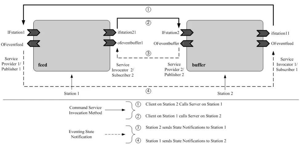
Figure 6: Proposed peer-to-peer event driven implementation of Station 1 & 2 of Festo test rig.
C. System Operation
In the test rig demonstration (Figure 1), the WS communication provides a way of passing SOAP (Simple Object Access Protocol) messages (i.e. XML) between addressed locations (e.g. requester, subscriber) over the SOAP protocol. The basic principle is described in this research by the client/server model. The server acts as the service provider/publisher and the client is a service requester/subscriber. For event-driven automation systems, the Web Services are utilised in the automation system to: 1- send and receive the device state notification and 2- request/initiate an operation on the device. In sending and receiving the device state notification (1), the server acts as an event source in terms of sending SOAP messages to the client, referred to as an event sink/receiver. In the service invocation
(2), the server is a service provider to the client (i.e. a requester). Based on this client-server functionality, the role of manufacturing entities (e.g. Processes, MES, and ERP) can be specified. In general, the process and machine is a server to integrate MES and ERP applications (clients). It is noted that, in the distributed peer-to- peer automation systems, the server and the client functionality will coexist within the control system (i.e. controllers) to allow the device-to-device communication as shown in Figure 6.
[image:5.595.59.546.319.554.2]components interact through WS-Discovery, Subscribe, and Eventing processes. Therefore, the programming complexity is substantially reduced.
The required server component in the control system is now known to the client and is ready to proceed with control system operation. During the operation, the interaction sequence between the server and the client is processed by:
1. Event server publishes the changing component state information sent to the event client/subscriber for a new update.
2. The client responds according to the defined state logic/transition conditions.
3. If the enable function on server is triggered, the server sends the requested SOAP message to invoke the specific operation on the WS component to trigger the action on the I/O channels.
This sequence runs repeatedly throughout the machine cycle. Additionally, the integration at the higher system levels is achieved in the similar manner through the implementation of WS interfaces to connect to the test rig for system control and monitoring.
VII. CONCLUSION AND FUTURE WORK
In this paper, a WS based automation system using a CB design approach is presented. The concept of a Web Services- based framework, capable of connecting various heterogeneous platforms and diverse equipment so that they may be integrated into a unified system and interact in a co-operative way, has been outlined in this paper. This concept of utilizing the Web Services protocol stack offers the potential for manufacturing automation to evolve, enabling a new paradigm of open standard, technology neutral and interoperability components from various device vendors. The development of device descriptions, embedded into the component and the driving of system intelligence down to the device level, ultimately offers the potential to eliminate the need for system integrators to undertake low level programming. The focus is on shifted towards building higher-level control applications and improving efficiency. This work investigates the configurability, and re-usability of control systems and seamless integration to business levels, thus enabling companies to become more agile and collaborative.
This approach employs DPWS on the control devices, which enables the evolution of an open standard for manufacturing automation to provide ease of integration and interoperability between various device platforms. From the perspective of process integration, the manufacturing and business applications can integrate with the control system via the common DPWS device interface in order to invoke the service via the SOAP- XML messages over the network. In summary, the integration of the CB design approach with WS on automation devices could be utilised not only in the automotive manufacturing domain, but also in other domains with soft-real time constraints. Further work is in progress to improve the I/O response speed, security and the system reliability regarding the potential loss of messages and error recovery due to the non- deterministic Ethernet network that needs to be addressed and managed.
ACKNOWLEDGMENT
The authors gratefully acknowledge the support of the EU FP7 SOCRADES and EPSRC, IMCRC, GAIN and BDA projects and their collaborator in enabling various aspects of this research.
REFERENCES
[1] D.M. Anders, “Mass customization, the Proactive Management of Variety,” in Build-to-Order & Mass Customization Casebook, CIM Press, 2004.
[2] A. Molina, C. A. Rodriguez ; H. Ahuett ; J. A. Cortés ; M. Ramírez ; G. Jiménez ;S. Martinez, “Next-generation manufacturing systems: key research issues in developing and integrating reconfigurable and intelligent machine,” in International Journal of Computer Integrated
Manufacturing, vol. 18, pp. 525-536, Oct-Nov 2005.
[3] M.F. van Assen, E.W. Hans, and S.L. van de Velde, “An agile planning and control framework for customer-order driven discrete parts manufacturing environments,” International Journal of Agile
Management Systems, vol. 2, no. 1, pp. 16 – 23, 2000.
[4] J. Yu and K. Krishnan, “A conceptual framework for agent-based agile manufacturing cells,” in Info System Journal, vol. 14, pp. 93-109, 2004.
[5] R.H. Weston, “Model-driven, component-based approach to reconfiguring manufacturing software systems,” International Journal
of Operations &Production Management, 19 (8), 834–855, 1999
[6] S.M. Lee, R. Harrison, A. West, “A Component-based Distributed Control System,” In 2nd International Conference on Industrial
Informatics(INDIN’04), June 24-26 2004, Berlin, Germany, 33-38.
[7] R. Harrison, A.W. Colombo, A.A. West and S.M. Lee, “Collaborative automation from rigid coupling towards dynamic reconfiguration production systems,” in Proceedings of 16th IFAC World Control
Congress, Prague, Czech Republic.
[8] “OPC Overview- OLE for process control,” Emerson Process Management©Whitepaper, March 2007,
Available: http://www.easydeltav.com/pd/WP_OPC_ Overview.pdf [9] W. Sperling, and P. Lutz, “Design applications for an OSACA
control,” in Proceedings of the International Mechanical Engineering
Congress and Exposition, Dalles/USA, November 16-21, 1997.
[10] C. Abadie and R. Neubert, “The mechatronic automation framework and its architecture requirements,” RIMACS Deliverable D 2.1
Internal Document, August 2006.
[11] F. Jammes, A. Mensch, and H. Smit, “Service-Oriented Device Communications using the Devices Profile for Web Services,” in 21st International Conference on Advanced Information Networking and
Applications Workshops (AINAW), 2007.
[12] F. Jammes, and H. Smit, “Service-Orient Paradigms in Industrial Automation,” in IEEE Transactions on Industrial Informatics, vol. 1, no. 1, pp. 62-70, 2005.
[13] P. Phaithoonbuathong, R. Harrison, A. West, R. Monfared,and T. Kirkham “Web services-based automation for the control and monitoring of production systems,” International Journal of
Computer Integrated Manufacturing, Volume 23 Issue 2, 126, Jan.
2010.
[14] L.M Sa de Souza, et al., “SOCRADES: A Web service based Shop Floor Integration Infrastructure,” in The Internet of Things Book, Publisher: Springer Berlin / Heidelberg, vol. 4952, March 2008. [15] Schneider Electric, Web Services team, Grenoble, France. Advantys
STB: System User Guide. Available:
![Figure 1: Ford Festo rig layout: A distributed CB design of a powertrain assembly machine [13]](https://thumb-us.123doks.com/thumbv2/123dok_us/1303936.660154/2.595.132.467.431.666/figure-festo-layout-distributed-design-powertrain-assembly-machine.webp)
![Figure 2: FTB integration framework employs request -response based approach [13].](https://thumb-us.123doks.com/thumbv2/123dok_us/1303936.660154/3.595.51.278.408.537/figure-integration-framework-employs-request-response-based-approach.webp)