TAILORING OPTICAL FIBERS FOR CELL TRANSFECTION
Nan Ma
A Thesis Submitted for the Degree of PhD at the
University of St. Andrews
2012
Full metadata for this item is available in Research@StAndrews:FullText
at:
http://research-repository.st-andrews.ac.uk/
Please use this identifier to cite or link to this item: http://hdl.handle.net/10023/3177
TAILORING OPTICAL FIBERS FOR CELL
TRANSFECTION
Nan Ma
This thesis is submitted for the degree of PhD
at the
University of St Andrews
ii Dedicated to
My parents & Jing,
With Love
iii
Tailoring Optical Fibers for Cell Transfection
Nan Ma
This thesis is submitted for the degree of PhD at the
University of St Andrews
iv
Abstract
Optical transfection is a promising technique for the delivery of
foreign genetic material into cells by transiently changing the permeability
of the cell membrane. Of the different optical light sources that have been
used, femtosecond laser based transfection has been one of the most
effective methods for optical transfection which is generally implemented
using a free-space bulk optical setup. Here in this thesis, a few novel
fabrication methods are devised to obtain easy and inexpensive
fabrication of microlensed optical fibers, which can be used to replace
traditional optical setup and perform femtosecond optical transfection.
These fabrication methods offer the flexibility to fabricate a microlens
which can focus femtosecond laser pulses at 800 nm to a small focal spot
whilst keeping a relatively large working distance. In conventional optical
transfection methods the foreign genetic material to be transfected is
homogenously mixed in the medium. This thesis reports the first
realization of an integrated optical transfection system which can achieve
transfection along with localized drug delivery by combining lensed fiber
based optical transfection system with a micro-capillary based microfluidic
system. Finally, based on an imaging fiber (coherent optical fiber bundle),
the first endoscope-like integrated system for optical transfection with
subcellular resolution epifluorescence imaging was built. The transfection
efficiency of these fiber based systems is comparable to that of a standard
free-space transfection system. Also the use of integrated system for
localized gene delivery resulted in a reduction of the required amount of
genetic material for transfection. The miniaturized, integrated design
opens a range of exciting experimental possibilities, such as the dosing of
tissue slices to study neuron activities, targeted drug delivery, and in
particular for using endoscope-like integrated systems for targeted in vivo
v
Declarations
1. Candidate’s declarations:
I, Nan Ma, hereby certify that this thesis, which is approximately 51,000
words in length, has been written by me, that it is the record of work
carried out by me and that it has not been submitted in any previous
application for a higher degree.
I was admitted as a research student in August, 2007 and as a candidate
for the degree of Doctor of Philosophy in June, 2012; the higher study for
which this is a record was carried out in the University of St Andrews
between 2007 and 2011.
Date …… Signature of candidate ………
2. Supervisor’s declaration:
I hereby certify that the candidate has fulfilled the conditions of the
Resolution and Regulations appropriate for the degree of Doctor of
Philosophy in the University of St Andrews and that the candidate is
qualified to submit this thesis in application for that degree.
Date …… Signature of supervisor ………
3. Permission for electronic publication:
In submitting this thesis to the University of St Andrews I understand that I
am giving permission for it to be made available for use in accordance with
vi
to any copyright vested in the work not being affected thereby. I also
understand that the title and the abstract will be published, and that a copy
of the work may be made and supplied to any bona fide library or research
worker, that my thesis will be electronically accessible for personal or
research use unless exempt by award of an embargo as requested below,
and that the library has the right to migrate my thesis into new electronic
forms as required to ensure continued access to the thesis. I have
obtained any third-party copyright permissions that may be required in
order to allow such access and migration, or have requested the
appropriate embargo below.
Access to printed copy and electronic publication of thesis through the
University of St Andrews.
Date …… Signature of candidate ……
vii
Acknowledgements
I would like to express my appreciation to my supervisors,
Professor Kishan Dholakia and Professor Frank Gunn-Moore, for this
great opportunity to work in their group, for their guidance, encouragement
and many valuable advices on the execution of my interesting
multidisciplinary projects.
I would also like to thank my colleagues and friends from the group.
Eddie Tan and Xanthi Tsampoula helped me to start my PHD on the
dangerous fiber project and guided me through the very beginning of my
PHD. Thanks Leilani Torres who helped me on the fiber photoporation
work and various other issues. The first fluorescent cell, after so many
days and nights working in the lab, that we successfully transfected, will
be remembered forever. And Patience Mthunzi, for helping me on cell
culture and answering all my biological questions. It’s a pity, although with
a lot of support from Kelvin Agboh and Maciej Antkowiak, the tissue transfection is still not working. I’d very much like to thank Praveen Ashok
and Rob Marchington, for their help on the lensed fiber fabrication. Without
this break point, I could never finish my PHD. And of course Dave
Stevenson, thanks for sitting behind me all these years and being a
reference book, not to mention numerous ideas and great Google
Sketchup you introduced to me. Thanks Heather, Rob, Maciej and Leilani,
and of course my supervisors, especially Frank, for the proof reading of
my awkwardly written thesis.
On a personal note, I’d like to thank my parents for their support,
encouragement, belief and unconditional love all my life. And also a very
big thanks to my dearest wife, my forever love, Jing, who endured with me
and has been supportive, encouraging and taking care of me throughout
my PHD. Jing always have faith in me, even when I was lost. Without her,
I would never have been able even to imagine where I am now. It is
viii
Publications
Peer Reviewed Publications
[1] X. Tsampoula, K. Taguchi, T. Cizmar, V. Garces-Chavez, N. Ma, S. Mohanty, K. Mohanty, F. Gunn-Moore, and K. Dholakia, "Fibre based cellular transfection," Optics Express 16, 17007-17013 (2008).
[2] N. Ma, P. C. Ashok, D. J. Stevenson, F. J. Gunn-Moore, and K. Dholakia, "Integrated optical transfection system using a microlens fiber combined with microfluidic gene delivery," Biomed. Opt. Express 1, 694-705 (2010).
[3] N. Ma, F. Gunn-Moore, and K. Dholakia, "Optical transfection using an endoscope-like system," J Biomed Opt 16, 028002-028007 (2011).
Conference Proceedings
[4] N. Ma, P. C. Ashok, F. J. Gunn-Moore, and K. Dholakia, "Fabrication of polymer microlens at the apex of optical fiber," in Photonics 2010 (Guwahati, India, 2010).
Patents
[5] Microlensed fiber-based photoporation (Europe Patent Application PCT/GB2011/000881)
Attended International Conference
ix
List of Abbreviations
1D 1 dimensional
2D 2 dimensional
3D 3 dimensional
AFM Atomic force microscope
CAD Computer aided design
CARS Coherent anti-Stokes Raman scattering
CCD Charge coupled device
CFP Cyan fluorescent protein
CHO-K1 Chinese hamster ovary
CSF Coreless silica fiber
CW Continuous wave
DCF Double-clad photonic crystal fiber
DEAE-dextran Diethylaminoethyl-dextran
DM Dichroic mirror
DNA Deoxyribonucleic acid
DsRed Discoideum sp, red fluorescent protein
EGFP Enhanced green fluorescent protein
FCS Fetal calf serum
FFB Fluorescence filter block
FFT Fast Fourier transform
FIB Focused ion beam
GFP Green fluorescent protein
GRIN Gradient refractive index
GVD Group velocity dispersion
HEK-293 Human embryonic kidney
HF Hydrofluoric acid
x
LMA-PCF Large mode area photonic crystal fiber
MEM Modified eagles medium
MitoDsRed DsRed fused with a mitochondrial targeting
sequence
MMF Multimode fiber
mRNA Messenger RNA
NA Numerical aperture
ND Neutral density; filter
NH4F Ammonium fluoride
NIR Near infrared
OCT Optical coherence tomography
PBF Photonic bandgap fiber
PCF Photonic crystal fiber
PtK2 Rat-kangaroo kidney epithelial
RNA Ribonucleic acid
ROS Reactive oxygen species
RT-PCR Real-time polymerase chain reaction
SEM Scanning electron microscopy or Scanning
electron microscope
siRNA Small interfering ribonucleic acid
SLM Spatial light modulator
SMF Single mode fiber
SNOM Scanning near-field optical microscopy
SPM Self-phase modulation
UV Ultra-violet
xi
Contents
Abstract i v
Declaration v
Acknowledgements vii
Publications viii
List of Abbreviations ix
1. Introduction to Cell Transfection Methods 1
1.1. Basic Principles of Gene Transfer……….3
1.1.1 Introduction……….3
1.2. Gene Transfer to Animal Cells Using Chemical and Physical Methods……….……….……….……….……5
1.2.1 Introduction……….……….……….……….5
1.2.2 Chemical Transfection Methods……….………7
1.2.2.1. Calcium phosphate……….………..7
1.2.2.2. DEAE-dextran……….……….………..7
1.2.2.3. Lipofection……….……….………8
1.2.3 Physical Transfection Methods……….……….………….9
1.2.3.1. Electroporation……….……….………...…….9
1.2.3.2. Microinjection……….……….……….10
1.2.3.3. Particle bombardment……….………...11
xii
1.2.3.5. Laser induced transfection………13
1.3. Summary and Conclusion………13
2. Femtosecond Laser Mediated Optical Transfection 15
2.1. Introduction……….…………...….……….……….15
2.2. Mechanisms of Femtosecond Laser Mediated Cell Membrane Permeabilization………..………….……….……….18
2.2.1 The Principle of Plasma Formation..………...18
2.2.2 Evolution of Free Electron Density and Breakdown Thresholds……….……….……….22
2.2.3 Chemical Effects of Low Density Plasmas……….25
2.2.4 Temperature Evolution during Pulse Series………...26
2.2.5 Bubble Formation during Optical Transfection………...28
2.2.6 Conclusion……….……….……….29
2.3. Development of Femtosecond Optical Transfection……….31
2.4. Delivery of Pulsed Laser Through an Optical Fiber………….….39
2.4.1 Introduction……….……….………....39
2.4.2 Dispersion……….……….………..41
2.4.2.1. Group velocity dispersion……….……….41
2.4.2.2. Self-phase modulation……….………….……….42
xiii
3. Microlensed Optical Fibers: Emerging Applications and
Techniques of Fabrication 47
3.1. Introduction……….……….……….………….…….47
3.2. Arc Discharge Technique……….……….…………..….50
3.3. Laser Micro-machining Technique……….……….……52
3.4. Polishing Technique……….……….………....53
3.5. Chemical Etching……….……….……….56
3.5.1 Selective Chemical Etching……….………..57
3.5.2 Protection Layer Method……….……….………….61
3.5.3 Tube Etching……….……….……….61
3.5.4 Multistep Etching……….……….……….….62
3.6. Microlens Fabrication Using Photosensitive Polymers…………64
3.6.1 Single-photon Polymerization Technique………..…….64
3.6.2 Two-photon Polymerization Technique……….……..…69
3.7. Focused Ion Beam Milling……….……….…..72
3.8. Summary……….……….……….………..75
3.9. Conclusion……….……….……….………..….76
4. Axicon Tipped Fiber for Cellular Transfection 78
4.1. Introduction……….……….……….…………..……78
4.2. The Fabrication of an Axicon Tipped Optical Fiber……….…….79
xiv
Beam from an Axicon Tipped Fiber……….83
4.3.1 The Characterization of the Output Beam from an Axicon Tipped Fiber……….………..……….83
4.3.2 Theoretical Modeling of the Output Beam of an Axicon Tipped Fiber………..………….……….86
4.3.3 Summary and Conclusion………....……….89
4.4. Experimental Procedure……….………..90
4.4.1 Experimental Setup……….………..………….90
4.4.2 Sample Preparation……….………...94
4.5. Results of Transfection……….……….95
4.6. Summary and Conclusion……….………..….97
5. Integrated Optical Transfection System Using a Microlens Fiber Combined with Microfluidic Gene Delivery 99
5.1. Introduction……….……….99
5.2. Experiment……….……….……….…….102
5.2.1 Fabrication and Characterization of Microlens Tipped Fiber……...……….……….……….……….102
5.2.2 Cell Transfection Using the Microlens Fiber……….108
5.2.3 Design of an Integrated System for Localized Drug Delivery……..………….……….……….…….111
5.3. Results and Discussion……….……….………….115
xv
6. Optical Transfection Using an Endoscope-like System 120
6.1. Introduction……….……….……….………...…….120
6.2. Experiment……….……….………..121
6.2.1 Imaging Fiber Preparation……….………..121
6.2.2 Laser Output Characterization and Modeling………….….125
6.2.3 Endoscope-like System……….………….……….126
6.2.4 Cell Culture and Imaging………....……….128
6.2.5 Cell Transfection Using an Endoscope-like System…..….130
6.3. Results and Discussions……….……….………….….131
7. An GRIN Lens Based Imaging Probe For Optical Transfection 135 7.1. Introduction……….……….……….………...…….135
7.2. Review of the Miniaturized Microscope Technique………...….136
7.2.1 Introduction……….……….………..136
7.2.2 Components……….……….………...……….137
7.2.2.1. Optical fiber……….……….……….137
7.2.2.2. Focusing mechanism……….……….….141
7.2.2.3. Scanning mechanism……….………….……….145
7.2.3 Embodiments……….……….……….…….147
7.2.4 Summary and Future……….……….……….151
xvi
7.4. Cell Transfection……….……….………...…….156
7.5. Summary and Conclusion……….……….157
8. Conclusion & Future Outlook 159
8.1. Summary of Thesis……….……….…………..……….159
8.2. Future Work……….……….………....164
8.2.1 Engineering Aspects……….……….………..164
8.2.2 Biology ……….……….……….165
Appendix A 167
A. The Simulated Output Beam Intensity Profiles of an Axicon Tipped Fiber……….……….……….………….…….167
1
Chapter 1:
1. Introduction to Cell Transfection Methods
As early as 1917, Albert Einstein set the theoretical foundations for the formulation of the laser in his paper “On the Quantum Theory of Radiation”. Fifty years after this on 16 May 1960, the first working laser
was built. Nowadays, the applications of lasers are evident in our daily life.
Lasers have been applied to surgery, national defence, printing and they
are continually gaining more importance in various research fields, such
as spectroscopy, laser annealing, interferometry, optical trapping and
microscopy [1, 2].
Laser delivery with optical fibers is a key development. As an
example, Charles Kao recently won the Nobel Prize in Physics in 2009 for
his ground-breaking achievements concerning the transmission of light in
fibers for optical communication. Optical fibers have become a major
conduit for communication within our society: it has been used to transfer
images, videos and music, globally in a fraction of a second. They have
also been extensively applied to the medical field and are becoming an
indispensable tool in this area.
Following the domination of the 20th century by physics and the 19th
century by chemistry, many specialists predicted that this century would be
the century of biology. Although, it has been approximately 5 decades
since the discovery of the structure and function of Deoxyribonucleic Acid
(DNA), which was probably the most significant biological discovery and
medical advancement of the 20th century, it was only until June 2000, that
the first draft of the human genetic code was completed. The use of
genetically personalized medicine has been to date fairly limited and the
all-purpose stem cell has not yet been produced. Nevertheless, substantial
advancement in genetics has been achieved: researchers have
discovered hundreds of genes that contribute, alongside with
2
and heart disease. These new understanding of disease mechanisms may
lead to new diagnostic tools and treatments in the near future. Genetic
material transfer is very important in current research for molecular and
cellular biology, and in particular in many applications involved in
biotechnology. Today, many gene transfection methods that were
developed for the transfection of cultured cell lines, are now entering in
vivo and clinical trials for gene therapy and DNA vaccines.
This thesis will present a multidisciplinary approach, which
combines the knowledge from three different fields: lasers, optical fibers
and gene transfer. With regard to the later, there are many traditional
transfection technologies that can be used to deliver foreign genetic
material into biological cells. A promising and relatively new method called
optical transfection, uses lasers to temporarily change the permeability of a cell’s membrane in order to achieve the same goal. Following the active
trend of miniaturization in the biophotonics field, optical fibers are used
throughout this work for the laser delivery and imaging of cells.
After a brief introductory chapter, which summarizes the basic
principles of gene transfer and contemporary non-viral gene transfection
technologies, Chapter 2 will introduce the development of an optical
transfection technique using a femtosecond laser. Chapter 3 will review
the different lensed fiber fabrication techniques. Chapter 4 will discuss the
first fiber based optical transfection work, which involved using an axicon
tipped single mode optical fiber for femtosecond laser delivery and
focusing and in Chapter 5, a novel lensed fiber fabrication method will be
presented, followed by an optical transfection experiment using an
integrated system combining a liquid delivery module. Chapter 6 will
demonstrate an upgraded version of the integrated system in Chapter 5,
with which the laser delivery, focusing and fluorescence imaging of
biological cells can all be realized through one system, without the need of
an extra objective lens. Chapter 7 will explore the feasibility of using a
gradient refractive index (GRIN) lens based imaging probe, with an
3
1.1. Basic Principles of Gene Transfer
1.1.1 Introduction
The techniques of DNA delivery into biological cells have been
widely studied and applied in basic research and biology [3-5]. This
indispensable tool can be used to study gene function and regulation, and
also the production of small amounts of recombinant proteins for analysis
and verification. Normally, gene transfer is used to express delivered
genetic material into the recipient cells and offer the possibility to observe a specific protein’s function. Genetic material transfer can also be used to
disable certain protein functions by interfering or inactivating certain
endogenous genes using small interfering Ribonucleic Acid (siRNA). The
application of gene transfer techniques ranges from using biological cells
to produce recombinant antibodies and vaccines, the production of
genetically modified animals, to gene therapy of the human body.
There have been various different names provided for different
types of DNA delivery mechanisms. The term transfection is generally
accepted as a way to describe the introduction of any sort of genetic
material DNA/RNA into a eukaryotic cell. The transfection of animal cells
thus encompasses all physical and chemical means of nucleic acid
delivery, which will be discussed in this chapter.
Regardless of the different transfection methods, successful gene
transfer into animal cells must achieve three objectives. First, the
exogenous genetic material must pass through the cell membrane. This is
a passive process, independent of the genetic material. Secondly, once it
traverses through the cell membrane, the genetic material must be
released in the cell and transported to a specific sub-cellular site for
expression or activation. In most transfection methods, genetic material is
delivered to the cytoplasm. DNA must then be transported to the nucleus.
However, this intrinsic DNA trafficking system is still poorly understood. On
4
is directly involved in cytoplasmic processes. Lastly, the exogenous
genetic material must be expressed and/or interact with the host genome.
There are often various transfection methods available to
researchers and therefore it is necessary to have the means to compare
each method and measure the relative transfection efficiency. Also, it is
essential to examine the activities of transfected genes. Some traditional
methods, such as real-time polymerase chain reaction (RT-PCR) and
northern blot hybridization have been developed to detect expression of
genes at the Messenger RNA (mRNA) level [6]. However, these methods
can be laborious and time-consuming, and where multiple genes have
been transfected these traditional methods may have difficulty in
distinguishing multiple gene products.
To avoid these problems, reporter genes can be used which
encode a product that can be easily detected and ideally quantified using
a simple, inexpensive and rapid assay. GFP (green fluorescent protein)
and its derivatives is one of the most commonly used in reporter genes [7].
GFP was originally discovered in the jelly fish Aequorea victoria; many
other fluorescent proteins are also naturally occurring from different coral
reef species. These proteins are fluorescent, can be long lasting and
observed under blue or Ultra-violet (UV) light. Therefore genes that
encode these fluorescent proteins can be used to identify easily
successfully transfected cells using a fluorescence microscope. Protein
expression and its subsequent changes can therefore be monitored in real
time. These sensitive genes can be used in living cells and animals and
are available in a variety of spectral excitation and emission wavelengths.
For some systems, the fluorescent signal from GFP is not strong enough;
however, modified GFP proteins (through specific mutations) with
improved emission at a wide-range of wavelengths [GFP, CFP (cyan
fluorescent protein) and YFP (yellow fluorescent protein)] have been
created.
Another fluorescent protein that was again first isolated from coral
5
crystal structure exhibits a similar topology to GFP, but additional chemical
modifications accounts for different spectra properties [7]. The reporter
gene used throughout this thesis is a mammalian expression vector that
encodes a fusion of DsRed with a mitochondrial targeting sequence (MitoDsRed), thereby specifically expressing DsRed only in the cell’s
mitochondria. In genetic engineering, a vector is also called a plasmid,
which is double-stranded DNA, and in many cases, circular, and can
replicate independently of the chromosomal DNA within a suitable host [8]. Therefore, once a small amount of MitoDsRed plasmid enters the cell’s
nucleus, it can multiply and subsequently express high levels of this red
fluorescent protein.
1.2. Gene Transfer to Animal Cells Using Chemical and Physical
Methods
1.2.1 Introduction
In this section, the focus will be on gene transfer methods using
chemical and physical means to carry the exogenous genetic material
across the cell membrane. Chemical methods normally involve mixing
specific chemicals and genetic material together to form synthetic
complexes, which can either enter the cell through endocytosis or fuse
with the cell membrane. The genetic material is then released into the cell
cytoplasm. Without the need to form synthetic complexes, physical
transfection methods can directly change the permeability of the cell
membrane and allow the genetic material to enter the cell, and in some
cases directly enter the nucleus. Techniques such as Nucleofector [9],
utilize the advantages of both methods and combine them to greatly
enhance the transfection efficiency.
The first boundary for transfection is the cell membrane, which is
6
negatively charged. Therefore, in chemical methods of transfection, in
order to allow passage of DNA to cross the cell membrane, a fusogenic
capsule or complex that carries a net positive charge are used to enclose
the DNA molecules. Following the fusing with the cell membrane, the DNA
encapsulated in the fusogenic particles, is released into the cytoplasm and
subsequently enters the nucleus via an intrinsic transport pathway, which
is still poorly understood. However, after entering the cell through an
endocytic process, the complexes are transported into endosomes and
can be degraded by lysosomes. Therefore, the complexes must escape
from the endosome into cytosol before being degraded. Certain reagents
such as chloroquine can be further added to the transfection protocol to
disrupt endosomes and the endosomal transport pathway to release DNA.
After which, the DNA can either simply diffuse into the cytoplasm directly,
or after the positively charged complex is neutralized by intracellular lipids
and other molecules. Only free DNA can be used for gene expression or interaction with the host cell’s genome.
The major difference between physical and chemical methods is
that, in physical methods, the DNA is delivered to the cytoplasm or
nucleus directly without having to consider the nature of the cell plasma
membrane or endosomal pathways. In this fashion, DNA molecules may
also suffer less damage from chemical agents. There are very few
similarities between the different physical methods and they are driven by
their respective physical principles. However, all of them require expensive
apparatus and need experienced experts to operate them. In the next few
sections, the most common chemical and physical transfection methods
7
1.2.2 Chemical Transfection Methods
1.2.2.1. Calcium phosphate
Calcium phosphate has been widely used in the chemical
transfection of animal cells [3]. The basic protocol for this method is that
DNA in a buffered phosphate solution and calcium chloride are mixed
together to generate a DNA-calcium phosphate co-precipitate, which
forms on the cells and enter the cells through endocytosis. Applying this
process on cells grown on a monolayer can provide a high transfection
efficiency. However, some cells are sensitive to the density of the
co-precipitate and also delicate primary cells often give poor results. In
addition, a major drawback of this method is that the size of the formed
particles depends on various factors including the method of mixing the
reagents. Therefore the results are not consistent and are difficult to
reproduce. Nevertheless, this inexpensive method is still easy, reliable,
and suitable for many cultured cell lines, and it can be used to provide
both transient and stable transfection.
1.2.2.2. DEAE-dextran
DEAE-dextran (diethylaminoethyl-dextran) was a popular method
for chemical transfection before the advent of lipofection reagents in the
1990s [3]. This soluble polycationic carbohydrate forms complexes with
DNA through electrostatic forces. The complexes have a net positive
charge and so interact with the negatively charged cell membrane and
then enter the cell through endocytosis (Fig. 1.1). The formed complexes
are smaller than the calcium phosphate precipitates and this limits the
maximum amount of DNA that can be used for each transfection
experiment. This method is inexpensive, simple and efficient, and although
the transfection efficiency is affected by different cell lines, this method
8
Fig. 1.1. Transfection with DEAE-dextran. Negatively charged DNA and
positively charged DEAE-dextran form a complex with a net positive
charge. This complex then interacts with negatively charged cell
membrane and promotes endocytosis. This graph is modified from Fig. 2.3,
[3].
1.2.2.3. Lipofection
There are two types of lipofection (lipid-mediated transfection),
which are the most widely used chemical transfection methods for gene
transfer into mammalian cells [3, 10]. In the first type, hydrophobic,
unilaminar phospholipid vesicles called liposomes are first created from
lipid molecules. The DNA is packaged inside the vesicles, which
subsequently fuses with the cell membrane after being mixed with cells in
the culture medium. DNA is then released to the cytoplasm directly (Fig.
1.2). Liposome-mediated transfection was the first non-viral in vivo DNA
transfection technique, which was suitable for potential gene therapy
studies.
Fig. 1.2. Transfection with liposomes. A fusogenic particle (liposome) is
first created with DNA inside before fuses with the cell membrane,
9 from Fig. 2.4, [3].
The second form is similar to the method using DEAE-dextran (Fig.
1.2). A complex called a lipoplex, is first created using cationic/neutral lipid
mixtures and DNA. The lipoplex has a net positive charge and interacts
with the negatively charged cell membrane, entering the cell through
endocytosis. This method is extremely simple. Lipoplexes are first created
by simply mixing a lipid preparation and the DNA in a serum-free medium
which is then added to the cells. This transfection method can be very
efficient for both transient and stable transfection. However, the lipids are
generally difficult to make in the laboratory and therefore must be
purchased.
1.2.3 Physical Transfection Methods
1.2.3.1. Electroporation
During electroporation, cells in buffered solution experience a
pulsed electric field, from which a number of pores of ~100 nm in diameter
are formed in the cell membrane and remain open for up to 30 minutes [3,
5, 11]. Free DNA molecules in the surrounding medium can then enter the
cells through these pores which will self-heal. This method is applicable to
many different cell lines, and especially those cells lines that cannot be
transfected via chemical methods. This technique was initially designed for
cells cultured in suspension; however, subsequent modifications have
extended the application of electroporation to adherent cells growing on a
polyethylene terephthalate or polyester membrane [12, 13].
This technique is very easy to implement. Normally, cells in a buffer
solution are treated with a short high voltage electric pulse or pulse train.
The amplitude, duration and the number of pulses applied to the cells is
adjusted to achieve the optimum transfection efficiency. Although,
10
viability after treatment is extremely poor, and so more cells are required
as compared to other transfection methods.
Recently, a new type of electroporation called nucleofection was
developed [14]. This new technique combines special designed
transfection reagents and electroporation using a specifically designed
electric field application for each cell line to promote the DNA delivery to
the nucleus. Many traditional difficult-to-transfect cells, including primary
neuron cells, have been transfected with this technique. Recently, needle
electrodes have also been used in in vivo and ex vivo electroporation.
Based on needle electrode, targeted single cell electroporation has been
achieved [13, 15].
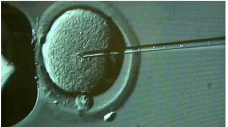
1.2.3.2. Microinjection
Fig. 1.3, shows a biological cell being held by a micropipette on the
left while a micro-needle is inserted into the cell nucleus from the right.
This technique is called microinjection and is used for the delivery of DNA
into oocytes and embryos of animals for the creation of transgenic animals
and artificial fertilization [16]. This technique also allows the injection of
DNA either into the cytoplasm or nuclei of cells directly without concerns
on the membrane boundaries and the inefficient endogenous DNA
transporting pathways. Therefore, this technique has been traditionally
used to transfect cells that are difficult to transfect by other methods.
Although this technique is highly efficient for individual cells, this
procedure is time consuming and has a low efficiency. The requirement of
DNA purity is also extremely high, which means laborious preparation is
needed. However, the automation of this technique can standardise the
procedure, reducing human error and increasing the injection rates and
11
Fig. 1.3.Microinjection technique. A cell is hold (sucked) by a micropipette
on the left while a micro-needle is inserted and delivering DNA into the cell
nucleus (Image from an unknown source on internet).
1.2.3.3. Particle bombardment
Particle bombardment is also known as biolistics or microprojectile
transfection [3, 5, 18]. This technique involves shooting micrometre sized
gold or tungsten particles coated in DNA, into cells or tissues. By adjusting
the force applied to the particles, the penetrating depth can be controlled.
This technique is especially useful for the transfection of cells with a thick
cell wall, such as with plant cells. For animal cells, this technique is
particularly useful for transfection of whole organs, tissue slices and even
living animals [19, 20]. The adjustment of the size, mass of the particles
and the force of the bombardment are essential for finding a balance for
penetration depth, transfection efficiency and tissue damage. The basic
principle and setup of this technique is shown in Fig. 1.4, where DNA
coated microprojectiles are spread onto a macrocarrier disc (Kapton disc);
a membrane restraining the gas is ruptured by an electronically driven
plunger and the disc is propelled toward the target tissue by the resulting
shock-wave; the macrocarrier is stopped by a screen while the
12
Fig. 1.4. Basic features of a particle bombardment transfection system.
DNA coated microprojectiles are spread onto a macrocarrier disc (Kapton
disc). A membrane restraining the gas is ruptured by an electronically
driven plunger and the disc is propelled toward the target tissue by the
resulting shock wave. The macrocarrier is stopped by a screen while the
microprojectiles continue on to penetrate the tissue. (Image from [19])
1.2.3.4. Sonoporation
Applying high intensity ultrasound waves of specific frequencies to
a dish of cells or tissue can also be used for the transfection of cells
[21-24]. The mechanism of sonoporation relies on ultrasound generating
bubbles which oscillate and collapse violently in the vicinity of the cell
membrane. This phenomenon is known as cavitation, which produces a
shock-wave causing the fluid to move against the cell membrane. The
resulting shear force changes the permeability of the cell membrane by
opening up specific holes. These self-healing holes remain open for
several minutes and allow macromolecules to enter the cell. At certain
ultrasound frequencies and exposure settings, this technique has no
observable adverse effects when applied to the human body. However, it
has been shown that this technique gives very low transfection efficiency
13
therapy has already been achieved in vivo and is being actively studied for
the use in in vivo targeted gene therapy [25, 26],
1.2.3.5. Laser induced transfection
Another in vitro transfection approach utilizes tightly focused laser
to change the permeability of the cell membrane [27]. Lasers of different
wavelengths [near infrared (NIR) [28] to UV [29]] and modes (continuous
[29] and pulsed [28, 30, 31]) can be used to achieve the transfection
through different mechanisms. So far, femtosecond laser mediated
transfection has been regarded as the most promising and the most
efficient optical transfection method, and so will be described in more
detail in the next chapter.
1.3. Summary and Conclusion
Cell transfection is at the heart of this thesis and it can be achieved
through various means. Before the presentation of optical fiber based
optical transfection techniques, which will be shown in the next few
chapters, it is necessary to understand what cell transfection is and
familiarize with other cell transfection methods. This chapter first reviewed
the basic principles of gene transfer, which include the brief introduction of
the definition of cell transfection and three basic objectives for any
successful transfections; the reporter genes that are commonly used to
assess different transfection methods and measure the transfection
efficiencies was also introduced. After that, most of the popular non-viral
(chemical and physical) gene transfection technologies were introduced
briefly. By comparison with these traditional gene transfection methods, it
is easier to understand the strength and weakness of laser based optical
transfection techniques. Although with low transfection throughput, optical
transfection has proven to be a more attractive transfection method. This
sub-14
cellular resolution and can be easily combined with almost any classic
microscopy, optical tweezers or microfluidic setups. The following chapter
will explore the most effective optical transfection method: femtosecond
15
Chapter 2:
2. Femtosecond Laser Mediated Optical Transfection
2.1. Introduction
Since the advent of the laser, it has not only been used to image
biological cells [32], but also to manipulate them – ablating, moving,
cutting and stretching using optical power [33-37]. In the previous chapter,
the basic principles of gene transfection using various different chemical
and physical transfection methods were introduced. Among these
methods, a novel laser manipulation technique for the introduction of
foreign material into biological cells, has been shown to have advantages
over the others: Firstly, it is a physically non-contact and sterile process.
The cells are normally manipulated by a focused laser beam delivered
from a remote distance through an objective. Therefore the cells can be
enclosed in an environment, such as a Petri dish or microfluidic chip
without exposure to the air during transportation from the preparation
bench to the transfection setup and throughout the whole experimental
process. Secondly, laser mediated transfection can be easily integrated
with almost any conventional imaging or microscopy setup. By coupling
the laser beam for optical transfection into an imaging setup, the
researcher can treat a particular area of a carefully chosen cell while
watching the process in real time. Furthermore, this technique provides
single cell selectivity with sub-cellular precision. With a sub-micron laser
spot integrated with modern microscopy technologies, one chosen cell
surrounded by many others can be transfected and leave the other cells
unaffected. Thanks to the miniaturization trend in the biophotonics world,
laser mediated transfection has the potential to be realized along with
other imaging modalities and optical manipulation tools on a fiber based
microendoscope, which will be discussed thoroughly in later chapters.
16
can be generally called optical injection. However, if the internalized
substance is a nucleic acid, such as DNA, RNA or siRNA, then the
process can also be called optical transfection [38]. Various laser sources
of different wavelengths (NIR [28] to UV [29]) and modes [continuous
wave (CW) [29] and pulsed [28, 30, 31]] can be used to achieve optical
transfection. However, the transfection mechanisms are different for
different laser systems. For CW lasers, the mechanism is probably due to
the highly localized heating [39, 40] or photochemical reaction [29]. Phenol
red is added to the buffer medium during transfection in order to increase
the heat absorption and so subsequently to increase the transfection
efficiency [29, 39-41]. For femtosecond lasers with high repetition rates
(~80 MHz), the permeabilization event is most likely due to the creation of
a low density plasma inducing chemical decomposition (bond breaking)in
conjunction with multiphoton-induced chemistry on the cell membrane [42].
At much lower repetition rates (1 kHz) with increased pulse energy, small
transient cavitation bubbles can be thermoelastically induced in the liquid
and open small holes on the cell membrane [42]. Nanosecond lasers can
generate electrons in the water, but also induce heating, cavitation bubble
formation and thermoelastic stress, which lead to the formation of a
shockwave [31, 42, 43]. Therefore, it is much easier to target an area
covered with tens of cells than a single cell using a nanosecond laser for
optical transfection. A comparison of the various laser sources and their
efficiencies is shown in table 2.1 [38]. Femtosecond lasers are currently
the most well understood powerful choice for single cell optical
transfection. Theoretically, a femtosecond laser should also cause the
lowest amount of damage to the cell due to the highly localized nonlinear
absorption and therefore achieve the highest survival rate and transfection
efficiency. Although by a similar mechanism, femtosecond lasers can
manipulate biological cells in many different ways, such as optoinjection
[44], microsurgery [45, 46] and nanopartical injection [47], but optical
17
Laser source: wavelength, pulse duration and
repetition rate
Reference Likely mechanism of action Transfection efficiency
193 nm/308 nm, 6 ns,
200 Hz
[48] Heating, thermoelastic
stress
0.5%
355 nm, ns, Hz [43,
49-51]
Heating, thermoelastic
stress
0.3 – 38%
405/488 nm, CW [29,
39-41, 52]
Hearting or
photochemical; typically
requires chemical
absorbers in the
medium such as phenol
red
less than
30%
532 nm, ns, kHz [53-55] Heating, thermoelastic
stress
30–80%
Approx. 800 nm, fs,
greater than 1 MHz
[28, 30,
36,
56-73]
Multi-photon effect;
generation of a low
density free electron
plasma cloud
often
greater
than
90%
1064 nm, ns, Hz [74, 75] Heating, thermoelastic
stress
less than
2%
1554 nm, fs, MHz [76] Multi-photon effect;
generation of a low
density free electron
plasma cloud
77%
2080 nm, a few Hz [77] Not known 41%
Table 2.1. Laser sources used for optical injection, probable mechanisms
of action and typical efficiencies. (Modified from Table 1 in [38] with newly
18
2.2. Mechanisms of Femtosecond Laser MediatedCell Membrane
Permeabilization
Throughout this thesis, cell transfection was instigated by a
femtosecond Ti: Sapphire laser emitting at 800 nm, with an output pulse
duration of ~100 fs and a pulse repetition frequency of 80 MHz (Coherent,
MIRA). With this set of laser parameters, optical transfection was
performed in the low-density plasma regime at pulse energies well below
the optical breakdown threshold and only slightly higher than those used
for nonlinear imaging. The induced moderate heating or thermoelastic
stresses can be ignored. Increasing the laser power, cumulative heating
will occur and long-lasting bubbles will be produced by tissue dissociation
into volatile fragments, which cause dislocations far beyond the laser
focus. Therefore long-lasting bubbles means that more damage to
biological cells occurs and it should therefore be avoided.
2.2.1 The Principle of Plasma Formation
The process of plasma formation from laser induced breakdown in
transparent biological media is schematically depicted in Fig. 2.1. The
quasi-free electrons are generated by an interplay of photoionization and
avalanche ionization. Quasi-free electrons, which are different from free
electrons generated in gases, are used to describe the generated
electrons by optical breakdown in condensed matter. These electrons
have gained enough kinetic energy to be able to move freely without being captured by local potential barriers. For simplicity, the term “free electrons”
19
Fig. 2.1. Interplay of photoionization, inverse Bremsstrahlung absorption,
and impact ionization in the process of plasma formation. Recurring
sequences of inverse Bremsstrahlung absorption events and impact
ionization lead to an avalanche growth in the number of free electrons [42].
Pure water can be used as a model instead of biological tissue to
study the laser induced plasma formation in bulk material, since the optical
breakdown threshold in water is very similar to that in biological tissue [78]
and optical transfection is performed in a liquid environment. According to
Sacchi, water can be treated as an amorphous semiconductor with a band
gap ∆ = 6.5 eV between valence and conduction bands [79]. However,
under the irradiation of high peak power femtosecond pulses, the
oscillation energy of the electron due to the electrical laser field has to be
taken into account for the calculation of the band gap potential and the
effective ionization potential of individual atoms can be written as [80]
̃
(2.1)where ω and F denote the circular frequency and amplitude of the
electrical laser field, e is the electron charge, and 1/m = 1/mc + 1/mv is the
exciton reduced mass that is given by the effective masses mc of the free
electron in the conduction band and mv of the hole in the valence band.
Under the scope of this thesis, multiphoton ionization and tunneling
20
2.1). Unlike single photon ionization where an atom or molecule absorbs
one photon with the energy that is equal to or higher than the ionization
energy, several photons are simultaneously absorbed during the
multiphoton ionization process [81]. Tunneling is an ionization process that
allows electrons escaping from an atom or molecule easily due to the
intense electric field distorted potential barrier of the atom or molecule [80].
The relative contribution to the photoionization from these two
mechanisms depends on the different field strengths and frequencies of
the electromagnetic field. With relatively low frequencies and large field
strengths, tunneling is more responsible for ionization, while with typical
larger optical frequencies and moderate field strengths, multiphoton
ionization occurs more easily [80]. At a wavelength of 800 nm, the
transition between two mechanisms occurs at field strengths of about 100 – 200 MW/cm, corresponding to irradiances of 1.3 – 2.6 x 10¹³
W/cm2
[82-84]. One example shows that the optical breakdown irradiance for 100 fs
pulses in distilled water is 1.1 x 10¹³ W/cm2, which is close to this transition
and very close to the irradiance used in femtosecond optical transfection
experiments. Therefore both multiphoton and tunneling ionization can be
responsible for the photoionization in femtosecond optical transfection [85].
After the generation of the first free electron through photoionization,
impact ionization will continue to produce more free electrons (Fig. 2.1).
The first generated free electron can continue to absorb photons in a process called ‘inverse Bremsstrahlung’, which involves colliding with a
third heavy charged particle (ions or atomic nuclei) to allow for energy and
momentum conservation [86]. After several inverse Bremsstrahlung
absorptions, the free electron is accelerated to a speed (kinetic energy) that is fast enough to ‘impact’ the other electron on the valence band and
so two slow-moving free electrons, are thus created through the impact
ionization (Fig. 2.1) [84, 87, 88]. These two electrons keep repeating the ‘inverse Bremsstrahlung’ process and ‘impacting’ more low energy
electrons, and finally lead to an avalanche growth in the number of free
21
electrons through diffusion out of the focal volume and through
recombination, and also if the energy gain through inverse Bremsstrahlung
is faster than the energy loss by collisions with heavy particles. The whole process can be called ‘avalanche ionization’ or ‘cascade ionization’ (Fig.
2.1) [42].
For impact ionization to happen, the kinetic energy of the impacting
electron must be large enough to assist the other electrons to overcome
the effective ionization potential ̃ and provide some extra energy for the
collision with a third particle for the conservation of energy and momentum.
This critical energy (kinetic energy), Ecrit, is decided by the band structure
of the water molecule and can be assumed to be equal Ecrit = 1.5 ̃ [42, 84,
89]. After overcoming the ionization potential ̃, the rest 0.5 ̃ is distributed
among two free electrons and the other colliding particle. Therefore, after
impact ionization, two free electrons have energies above the conduction
band and need to gain less than 1.5 ̃ to reach the critical energy [84, 90].
However, the average energy leading impact ionization is larger than Ecrit
because the impact ionization rate increases with kinetic energy and in
order to achieve avalanche ionization, a very high ionization rate is
needed [84, 89, 91]. Considering both factors, it is assumed that the
average energy gain required for a free electron (above the conduction
band) to cause impact ionization is 1.5 ̃, as depicted in Fig. 2.1 [42].
To study optical transfection, the important range of plasma
formation is from a point below the optical breakdown threshold to a point
slightly over it. In aqueous media with femtosecond pulses, the indication
of optical breakdown is the formation of cavitation bubbles. By contrast,
from a theoretical point of view, the optical breakdown threshold is defined
by the critical free electron density at the laser focus, above which the
plasma becomes both strongly reflective and absorbing [83, 84, 90, 92,
93]. At 800 nm, the approximate value of the free electron density is 1021
cm-3 [42]. This is a constant because from experimental measurements, it
has been shown that the bubble formation is always related to a plasma
22
2.2.2 Evolution of Free Electron Density and Breakdown
Thresholds
Based on the qualitative description of the plasma formation
process as discussed above, a numerical simulation has been developed
to study the evolution over time of the free electron density under the
influence of the laser field [42]. Considering the photoionization (including
multiphoton and tunneling ionization), cascade ionization, and losses
through diffusion of electrons out of the focal volume and recombination,
the free electron rate equation can be written as [94]
(2.2)
The first term on the right hand side, ,represents the free electrons
produced by photoionization. The second term represents the electron
production by cascade ionization; and the last two terms describe the
electron losses. indicates the free electron density, ,
and
are the cascade ionization rate, diffusion loss rate and recombination rate
respectively. The laser pulse is assumed to have a Gaussian time
variation and focused into pure water through a microscope objective with
a numerical aperture of NA = 1.3. More detailed numerical simulation can
be found in [42].
From the numerical simulation, the evolution of the free electron
density under the irradiation of a single 100 fs, 800 nm laser pulse at
the optical breakdown threshold, is presented in Fig. 2.2(a) [42]. The time t
is normalized with the 100 fs pulse duration ( ) and the 0 on the time axis
in Fig. 2.2(a) indicates the center (peak) of a laser pulse. The contribution
of photoionization to the total free electron density is plotted as a dotted
line. Fig. 2.2(b) shows the maximum free electron density that can be
achieved using different laser pulse irradiance I, which is normalized with
23
Fig. 2.2. (a): evolution of the free electron density during the laser pulse at
the optical breakdown threshold for 100 fs and 800 nm pulses. The time t
is normalized with respect to the laser pulse duration . The contribution
of multiphoton ionization to the total free electron density is plotted as a
dotted line. (b): maximum free electron density achieved during the
laser pulse as a function of irradiance, for the same laser parameters. The
irradiance I is normalized with respect to the threshold irradiance IR. The
threshold IR and the corresponding value of are marked by dashed
lines [42].
Due to the ultrashort pulse duration of the femtosecond laser, a
very high irradiance can be achieved and so produce free electrons
through photoionization. With a single 100 fs pulse at 800 nm, the total
number of free electrons generated through avalanche ionization is only
12 times larger than the number generated through photoionization [Fig.
2.2(a)]. Thus the contribution of photoionization cannot be ignored. It can
be seen that the avalanche ionization can be initiated at irradiance values
noticeably lower than the optical breakdown threshold, because there is
never a lack of seed electrons for avalanche ionization [Fig. 2.2(b)]. The
maximum free electron density can be reached at the relative irradiance
value is shown in Fig. 2.2(b), from which and with the support of
experiment results [92], it can be seen that plasmas with a wide density
24
ultrashort pulse in bulk transparent media. The free electron density can
be controlled through the tuning of relative irradiance values. Thus low
density plasma mediated chemical, heating and thermomechanical effects
can be precisely controlled by varying the irradiance. These effects are
also very well localized due to the nonlinearity of the plasma formation
process.
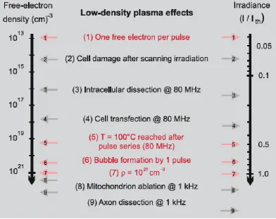
The irradiance and radiant exposure (irradiance multiplied by pulse
duration) that is needed to reach the breakdown threshold with a critical
free electron density of 1021 cm-3 is shown in Fig. 2.3 [42], from which it
can be seen that pulse durations at the ranges below and above 10 ps
show very different behaviours. For the pulse durations shorter than 10 ps,
the threshold radiant exposure shows only a weak dependence on pulse
duration. This reflects the fact that, when the laser pulses are shorter than
10 ps, free electrons can be produced in a very short time before the
combination process starts and this set of produced free electrons (with a
constant density at the threshold) results in a roughly constant energy
density within the focal volume. This is proved by the bubble formation
experiments that always require a specific plasma energy density, which
varies little with different ultrashort pulse durations and wavelengths [42].
For the pulses longer than 10 ps, the recombination happens within one
pulse duration time and therefore the longer the pulse, the larger the
radiant exposure is needed. For the analysis of pulses longer than 10 ps,
25
Fig. 2.3.Calculated optical breakdown thresholds (1021 cm-3) as a function
of laser pulse duration for various laser wavelengths [42]. (a) Irradiance
thresholds, (b) radiant exposure thresholds.
2.2.3 Chemical Effects of Low Density Plasmas
Biological tissue is modified by low density plasma through
chemical reactions. There are mainly two types of chemical effects. The
first one, reactive oxygen species (ROS), such as OH* and H2O2, are
generated through various pathways following ionization and dissociation
of water molecules [95-97]. ROS have negative effects (causing cell
damage [56]) on biological tissues. The second type of chemical effects
can directly change the organic molecules in resonant electron-molecule
scattering. Electrons captured into a molecule can cause the
fragmentation of biomolecules [96, 98-100]. ROS and free electrons
mediate cell membrane dysfunction and DNA strand breaks [56] and this
is also believed to be the main mechanisms of the permeabilization of the
membrane during femtosecond optical transfection. More discussion about
the implications of laser induced low density plasma on biological cells and
tissues will be presented in section 2.2.5 and more details about these
26
2.2.4 Temperature Evolution during Pulse Series
Thermal effects play a big role in some forms of laser surgery [101].
Therefore, to obtain a better understanding of femtosecond optical
transfection, the temperature change near the laser focus needs to be
investigated. In the previous sections, it was shown that the laser energy
transferred to the medium forms plasma in the laser focus. After that, the
fast moving electrons transfer the energy to heavy particles through
collisions and non-radiative recombination processes, resulting in the
heating of the atomic, molecular, and ionic plasma constituents [42]. For
femtosecond lasers, the pulse duration is much shorter than the electron
collision and the recombination process. Therefore, the plasma formation
and heating (transferring of electron energy to heavy particles) can be
treated as two consecutive and independent processes for the study of
temperature evolution. The total energy delivered by one laser pulse can
be calculated by simply multiply the total number of produced free
electrons by the mean energy gain of them. Then taking into account the
repetition rate of the laser (80 MHz), wavelength (800 nm), pulse duration
(100 fs), free electron density, and properties of pure water, the evolution
of the temperature distribution within the interaction volume can be
27
Fig. 2.4. Temperature evolution (black line) at the center of the laser focus
produced by a series 800 nm, 100 fs pulses focused into water at a NA =
1.3 with a repetition rate of 80 MHz. The volumetric energy density
deposited per pulse is always 1 Jcm-3 at the focus center. The dashed
lines represent the temperature decay after a single pulse. For comparison,
the temperature evolution during CW irradiation with the same average
power as for the pulsed irradiation is also shown (red line) [42].
Fig. 2.4 shows the calculated temperature evolution at the center of
the laser focus at a NA of 1.3 and with each pulse an energy density of 1 J
cm-3 (corresponding to an irradiance value below the optical breakdown
threshold) at the center of the initial temperature distribution is deposited
[42]. For other values of the energy deposition, the shape of the curve in Fig. 2.4 will be the same but with a temperature increase (ΔT) proportional
to the deposited peak energy density. For comparison, the temperature
evolution during CW irradiation with the same average power as for the
femtosecond laser, is also shown in the same graph (red curve).
An 80 MHz repetition rate corresponds to a delay of 12.5 ns
between two consecutive femtosecond pulses. It can be seen that in Fig.
2.4 the temperature is first raised by 0.2 K by a single laser pulse and after
12.5 ns before the temperature drops back to the original state, the
28
tens of microseconds the temperature is elevated to a balanced level,
which is 6.8 times larger than the temperature raised by a single pulse.
Moderate heat accumulation effects can be seen. With higher irradiance
(still under the breakdown threshold), larger temperature rises can be
achieved. However, thermal denaturation of biomolecules may only be a
minor effect since more free electrons will be produced and induce
chemical effects simultaneously [42].
2.2.5 Bubble Formation during Optical Transfection
The time interval for temperature rise under the irradiation of a
single femtosecond pulse is much shorter than the acoustic transit time
from the center of the laser focus to the surrounding medium. Therefore,
the thermoelastic stresses caused by the temperature rise are confined in
the focal volume and lead to the rise in local pressure [102-104].
Cavitation bubbles will be formed when the tensile strength of the liquid is
exceeded (optical breakdown). However, for cell surgery with a laser of
high repetition rate ~80 MHz, long-lasting (few seconds) bubbles will be
created before the pulse energy reaches the level of cavitation bubble
(sub-microsecond) formation. The long-lasting bubbles probably arise from
the dissociation of biomolecules into volatile, non-condensable fragments
[105-107]. The mechanisms of this dissociation can be attributed to free
electron chemical and photochemical bond breaking as well as to the
accumulative thermal effects [42]. During optical transfection, the
appearance of long-lasting bubbles means more damage to the treated
cell and it is therefore better if it can be avoided. The bubble formation
does not belong to the mechanisms contributing to optical transfection and
thus will not be introduced in this chapter. More specific information about

![Fig. 2.9. Illustration of the raster scan irradiation. The grid (10 x 10 µm) covers the whole area of the dish in a untargeted manner [69]](https://thumb-us.123doks.com/thumbv2/123dok_us/8716657.383979/53.595.132.493.166.424/fig-illustration-raster-scan-irradiation-covers-untargeted-manner.webp)

![Fig. 3.4. Different types of fiber tip fabricated using polishing based technique. (A) Wedge shaped microlens [168]; (B) Elliptical microlens [167]; (C, D) Elliptical microlens [177]; (E, F) Elliptical microlens [174]; (G) Fiber tip for scanning near field](https://thumb-us.123doks.com/thumbv2/123dok_us/8716657.383979/72.595.130.496.146.380/different-fabricated-polishing-elliptical-microlens-elliptical-elliptical-microlens.webp)


