A Logical Approach for Behavioural Composition of
Scenario-based Models
J. K¨uster Filipe Bowles1, B. Bordbar2, and M. Alwanain2
1
School of Computer Science, University of St Andrews Jack Cole Building, North Haugh, St Andrews KY16 9SX, UK
2
School of Computer Science, University of Birmingham Edgbaston, Birmingham B15 2TT, UK
{b.bordbar|m.i.alwanain}@cs.bham.ac.uk
Abstract. As modern systems become more complex, design approaches model different aspects of the system separately. When considering (intra and inter) sys-tem interactions, it is usual to model individual scenarios using UML’s sequence diagrams. Given a set of scenarios we then need to check whether these are con-sistent and can be combined for a better understanding of the overall behaviour. This paper addresses this by presenting a novel formal technique for composing behavioural models at the metamodel level throughexact metamodel restriction (EMR). In our approach a sequence diagram can be completely described by a set of logical constraints at the metamodel level. When composing sequence di-agrams we take the union of the sets of logical constraints for each diagram and additional behavioural constraints that describe the matchingcomposition glue. A formal semantics for composition in accordance with the glue guides our model transformation to Alloy. Alloy’s fully automated constraint solver gives us the solution. Our technique has been implemented as an Eclipse pluginSD2Alloy.
Keywords: Sequence diagrams, Behavioural Composition, Event Structures, Alloy
1
Introduction
As modern systems become more complex, design approaches model different aspects of the system separately. When considering (intra and inter) system interactions, it is usual to model individual scenarios using UML’s sequence diagrams. Given a set of scenarios we then need to check whether these are consistent and can be combined for a better understanding of the overall behaviour. The overall behaviour of the system can be obtained step by step by composing individual scenario-based models.
paper, we use Alloy [12] for finding the solution. Using Alloy for model composition is an active area of research [19, 23]. Whilst most existing research focuses on static models, the focus of this paper is on dynamic models. The proposed method in this pa-per consists of two steps. First, create thelogical constraintsthat uniquely characterise each model by restricting the metamodels. Second, producebehavioural constraintsfor combining the models. These consist of constraints indicating how elements from both models may be matched and additional constraints such as orderings that may have to be preserved. The augmented model for the composition (if existing) needs to satisfy theconjunction of all these constraints. The composed model is semantically equiva-lent to one obtained by an enriched form of parallel composition with synchronisation and additional constraints on permitted combined behaviour. The automatic generation of such a solution is the main novelty and contribution of this paper.
In general, metamodels represent the model elements and their relationships. Log-ical statements written in the context of metamodels play a key role in expressing the well-definedness of model elements, defining model equality, and so on. We extend the use of logical constraints and for a given model we produce further constraints to
uniquelydetermine the model. We refer to the process of identifying such logical con-straints asExact Metamodel Restriction (EMR). As we show in this paper, EMR can be used in the automated instantiation of models via constraint solvers. For example, in [2] starting from any UML sequence diagram, using the Alloy model finder for the sequence diagram metamodel and correct set of constraints, Alloy can be used to au-tomatically recreate the original sequence diagram. Given any two modelsM1andM2 representing two partial specifications (e.g., two sequence diagrams), through EMR we produce two sets of constrainsL1andL2on their metamodels that uniquely identify them. To compose the two models we may requireallconstraints in the two sets to be true. This would be a very restrictive form of composition. Instead we give the designer a novel way to influence the obtained composition by specifying behaviour that should never occur or sequences of events that must occur in a given order. In other words, it allows the designer to prioritise on specified behaviour. We refer to these additional constraints asbehavioural composition glueand present a formal semantics for it.
The paper is organised as follows. Section 2 describes interactions in UML and introduces an example which is used throughout the paper to illustrate our approach. Section 3 introduces labelled event structures (LES), our semantic interpretation of in-teractions and a guide to the correct composition solution. Section 4 shows the trans-formation into Alloy. Composition is treated with LES in Section 5 and with Alloy in Section 6. Related work is described in Section 7. Section 8 concludes the paper.
2
Interactions in UML
Sequence diagrams are described in UML’s superstructure specification [17] both through aconcreteand anabstract syntax. The concrete syntax consists of the graphical nota-tion for a sequence diagram, whereas the abstract syntax is given by a metamodel which defines all the elements of a sequence diagram model and their possible relationships. Aninstanceof the metamodel corresponds to a concrete sequence diagram.
Concrete Syntax:An interaction captured by a sequence diagram involves a group of objects which exchange messages between each other to achieve a particular goal. Each object has a vertical dashed line calledlifelineshowing the existence of the ob-ject at a particular time. Points along the lifeline are calledlocations(a terminology borrowed from LSCs [11]) and denote the occurrence of events. The order of locations along a lifeline is significant denoting, in general, the order in which the corresponding events occur. Aninteractionbetween several objects consists of one or more messages, but may be given further structure through so-calledinteraction fragments. There are several kinds of interaction fragments includingseq(sequential behaviour),alt (alterna-tive behaviour),par(parallel behaviour),neg(forbidden behaviour),assert(mandatory behaviour),loop(iterative behaviour), and so on [17].
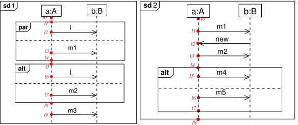
Consider the following sequence diagrams which show a slightly adapted example from [10]. Fig. 1 (left) shows an interaction with two consecutive interaction fragments (a parallel followed by an alternative fragment), and Fig. 1 (right) shows a different interaction involving the same instances and a few additional messages.
l9
alt
l0 l1
l2
l3 l4
l5
l6
l7
l8
par sd1
a:A b:B
m1 i
m2 j
m3
l4
sd2
a:A b:B
m5
l0
l6 l7 l8
m1
l2 new l3
l1
m2
l5 m4
[image:3.612.163.455.517.640.2]alt
InteractionConstraint InteractionOperand
interactionOperator:InteractionOperatorKind
CombinedFragment
GeneralOrdering
Message
+events {ordered}
+covered
* 1
+sendEvent
* *
*
+guard
*
+enclosingOperand
0..1 1 +operand 1..*
0..1
0..1
*
0..1
*
+next 1
* *
+covered +coveredBy
+fragment
0..1
+enclosingInteraction
0..1 0..1 0..1 0..1
+receiveEvent 1
1 InteractionFragment
OccurrenceSpecification Lifeline Interaction
[image:4.612.134.499.113.296.2]MessageEnd
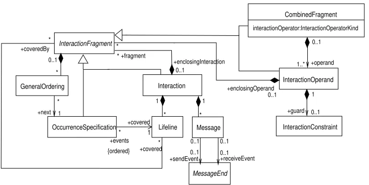
Fig. 2.The Interactions Metamodel.
In both diagrams, all messages are sent asynchronously between objectsa andb
(only messagenewis sent bybtoa). The locations along the lifeline of objecta are shown explicitly in both diagrams. The importance of locations is described later in the paper. In particular, the distinction between the syntactic notion of a location on a sequence diagram from its semantic counterpart of an event will be clarified. In Fig. 1 messagesiandm1are sent/received in parallel followed by messagejor messagem2 (alternative), and further followed by messagem3(irrespective of the previous alterna-tive choosen). In Fig. 1, three messages are sent/received before reaching an alternaalterna-tive fragment and choosing between messagesm4 orm5. These diagrams will be used to show how we can compose diagrams under certain constraints.
Abstract Syntax: A metamodel can be understood as a model of a collection of models. A metamodel is usually a structural model given as a UML class diagram often with additional constraints given in UML’s constraint language OCL. Metamodels can be built for both static and dynamic models but focus only on the structural aspects of the model. In this paper we look at sequence diagrams. The metamodel of a sequence diagram, also known as an interaction, shows the structure of such a diagram in terms of the model elements present and their relationships. The dynamic interpretation is not given in the metamodel, and must be defined separately. See ours in Section 3.
The UML superstructure specification [17] defines the interaction’s metamodel in a package showing different elements and their relationships separately in different dia-grams. To make the presentation simpler, we use a subset of the metamodel for interac-tions and show it as one class diagram in Fig. 2. We capture the main nointerac-tions that we need for the present paper.
An Interactioncontains zero or more instances of Lifeline,Message and InteractionFragment. A Messageusually has asendEvent MessageEndand a receiveEvent MessageEnd associated to it. In the present paper, we assume that
calledMessageOccurrenceSpecification(not shown). It is possible for aMessage to have beenfound, or similarlylost, in which case it does not have asendEventor areceiveEvent. AMessagecannot be simultaneously found and lost. AMessage has attributesmessageKindandmessageSort(not shown in the diagram). These at-tributes have a type with the same name which are enumeration types used to indicate whether a message is lost, found, complete or unknown (MessageKind), or a syn-chronous/asynchronous call, createMessageand so on (MessageSort). ALifeline has attributes for the nameandclassassociated to the object that is denoted by the lifeline (not shown in the diagram). AnInteractionFragmentis an abstract class which is further specialised into anOccurrenceSpecification, anInteraction, aCombinedFragmentor anInteractionOperand. Thelocationsmentioned in Sec-tion 2 correspond to instances of OccurrenceSpecification. These are the or-dered events that cover a Lifeline. A GeneralOrderingrepresents a binary re-lation between twoOccurrenceSpecifications. The metamodel contains relations beforeandafter, but we restrict ourselves to a relationnextwhich is all we require for our purposes. ACombinedFragmenthas an attributeinteractionOperatorof enumeration typeInteractionOperatorKind(par,alt,seq,loop,assert, and so on), and contains one or more operands which areInteractionOperands. An InteractionOperandmay have aguardwhich is an InteractionConstraint. AnInteractionOperandencloses either severalOccurrenceSpecifications, an Interactionor anotherCombinedFragmentindicating nesting of fragments.
An instance of the metamodel represents a concrete interaction or sequence dia-gram. The interaction from Fig. 1 can be captured using the abstract syntax as an in-stance of the metamodel (not shown here).
We have developed a toolSD2Alloythat takes a sequence diagram described by its abstract syntax and transforms it into an Alloy model. Alloy [12] is a declarative textual modeling language based on first-order relational logic. Alloy is supported by a fully automated constraint solverAlloy Analyzerwhich enables the analysis of system prop-erties by searching for instances of the model. It is possible to check whether certain properties of the system are present. This is achieved via an automated translation of the model into a Boolean expression, which is then analysed by SAT solvers such as SAT4J [5] embedded within theAlloy Analyzer.
3
Semantics of Interactions
Prime event structures [22], or event structures for short, describe distributed com-putations as event occurrences together with binary relations for expressing causal de-pendency (calledcausality) and nondeterminism (calledconflict). The causality relation implies a (partial) order among event occurrences, while the conflict relation expresses how the occurrence of certain events excludes the occurrence of others. From the two re-lations defined on the set of events, a further relation is derived, namely theconcurrency
relationco. Two events are concurrent if and only if they are completely unrelated, i.e., neither related by causality nor by conflict. The formal definition as defined for instance in [22] is as follows.
Definition 1 Anevent structureis a tripleE= (Ev,→∗,#)whereEvis a set of events and→∗,#⊆Ev×Evare binary relations calledcausalityandconflict, respectively. Causality→∗is a partial order. Conflict#is symmetric and irreflexive, and propagates over causality, i.e.,e#e0 →∗e00 ⇒e#e00for alle, e0, e00∈Ev. Two eventse, e0 ∈Ev areconcurrent,e co e0iff¬(e→∗e0∨e0 →∗e∨e#e0).
We omit further technical details on the model, but note that for the application of event structures as a semantic model for sequence diagrams we usediscreteevent struc-tures. Discreteness imposes a finiteness constraint on the model, i.e., there are always only a finite number of causally related predecessors to an event, known as thelocal configurationof the event (written↓e). A further motivation for this constraint is given by the fact that every execution has a starting point or configuration.
Event structures are enriched with a labelling functionµ:Ev→Lthat maps each event onto an element of the setL. This labelling function is necessary to establish a connection between the semantic model (event structure) and the syntactic model (here a sequence diagram). The labelling function used here is a partial function. Intuitively, each location marked along a lifeline of an object in a sequence diagram corresponds to one (possibly more) event(s) in the labelled event structure. The set of labels used could be the set of locations in a sequence diagram but is usually more concrete infor-mation on what the location represents: the initialisation of an object, sending/receiving a message, beginning/ending an interaction fragment, etc.
LetI denote the set of objects involved in the interaction described by sequence diagram SD, and M esthe set of asynchronous messages exchanged. Let the set of labelsLbe given byL = {(m, s),(m, r) | m ∈ M es}. An event with label(m, s)
corresponds to the sending of messagemwhereas an event with label(m, r)indicates the receipt of messagem.
Definition 2 A modelMSD= (E, µ)for a sequence diagramSDis obtained by
com-position of the modelsMa = (Ea, µa)of each object instance a ∈ I. InMSD, the
set of events is given by Ev = S
a∈IEva, and event labels are as before, that is,
µ(e) = µa(e)for e ∈ Eva. Let mbe a message sent between objecta and object
b, and letE1 ⊆ Eva with µa(e1) = (m, s)for alle1 ∈ E1, andE2 ⊆ Evb with
µb(e2) = (m, r)for alle2∈E2. Then necessarily|E1|=|E2|and for eache1∈E1
there is a uniquee2∈E2for eache1such thate1 →e2and local conflict#a
propa-gates over→to obtain conflict#inM.
(j,s) # g0
g1
g2 g3
g4
g5
g6 g7
g81 g82
g91 g92
(m1,r) (i,r)
(m2,r)
(m3,r) (m3,r)
(j,r) e0
e1
e2 e3
e4
e5
e6 e7
e81 e82
e91 e92
(m1,s) (i,s)
(m2,s)
(m3,s) (m3,s)
[image:7.612.192.427.114.260.2]#
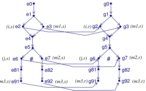
Fig. 3.Model for sequence diagramsd1.
The overall event structure model for the diagram from Fig. 1 is given in Fig. 3. Conflict propagation is not shown explicitly but is as expected and propagates over the new causality relations gained from communication. For example,e6#ae7and conse-quentlye6#e7. In addition, sincee7→g7by conflict propagation we also havee6#g7.
Definition 3 LetMSD = (E, µ)be a model for sequence diagramSD whereE =
(Ev,→∗,#)is an event structure. A subset of eventsC⊆Evis aconfigurationinE
iff it is both 1)conflict free: for alle, e0 ∈ C,¬(e#e0)and 2)downwards closed: for anye ∈Cande0 ∈Ev, ife0 →∗ ethene0 ∈C. A maximal configuration denotes a trace.
For example, the following is a trace for Fig. 3:C={e0, e1, e2, e3, e4, e5, e7, e82, e92, g0,
g1, g2, g3, g4, g5, g7, g82, g92}which denotes the occurrence ofm2and notj.
4
Exact Metamodel Restriction
We propose a method that considers both the structure and dynamic interpretation of a sequence diagram when producing an Alloy model. The model is obtained byexact metamodel restriction, that is, by considering the abstract syntax of a diagram and con-straints obtained from the dynamic (LES based) interpretation we generate the exact solution in Alloy that corresponds to the intended sequence diagram. This approach is also used to obtain a composed model for two (or more) sequence diagrams later on.
signatures may contain fields which are captured by relations. Axioms in Alloy are calledfactswhich can be given a name. These must hold at any time. Alloy formu-lae often use the atomic predicatein(inclusion), standard connectives from first-order logic, and quantifiersall(universal) andsome(existential). In general, expressions in Alloy are built using set theoretical relational operators and constants.
All interaction metamodel elements of Fig. 2 are transformed into top-level signa-tures in Alloy, and separate transformation rules treat each one. We omit the basic rules for Lifeline, Message and Event (denotingOccurrenceSpecification). It suf-fices to say that the lifeline transformation rule creates a domain calledLifelineas an abstract signature. Furthermore, each lifeline object has fields nameandclass. For each concrete instance declared in a sequence diagram we obtain declarations. The
Eventsignature has a fieldcoverwhich corresponds to a relationship with a life-line it belongs to, and a fieldnextwhich corresponds to a relationship with a set of events. This relationship corresponds to theimmediatecausality relation from our la-belled event structures. TheMessagesignature has two fieldssendandreceive
both corresponding to one event. We have additional facts to indicate the order of the events associated to a message. Messages also have a name which are introduced when creating a concrete message as shown below.
1 one sig sd1_i extends Message {name:one i} 2 one sig sd1_m1 extends Message {name:one m1} 3 lone sig sd1_m2 extends Message {name:one m2} 4 lone sig sd1_j extends Message {name:one j} 5 one sig sd1_m3 extends Message {name:one m3}
The lines above show the declaration of the messages fromsd1(see Fig. 1 on the left). In Alloy, we cannot have two signatures with the same name. Since messages may be repeated accross different sequence diagrams we avoid this problem by adding the information from which diagram it belongs to, in this casesd1. Similarly forsd2.
one sig sd2_m1 extends Message {name:one m1}
one sig sd2_m2 extends Message {name:one m2}
Some of the messages (lines 3-4 above) are declared aslone(a multiplicity key-word in Alloy meaning 0 or 1), while others areone(exactly one). This has to do with the fact that messages within an alternative fragment are not guaranteed to occur. We will explain this in more detail later on.
6 lone sig e2extends Event{} 7 lone sig e3extends Event{} 8 lone sig e6extends Event{} 9 lone sig e7extends Event{} 10 lone sig e9extends Event{} 11 lone sig g2extends Event{} 12 lone sig g3extends Event{} 13 lone sig g6extends Event{} 14 lone sig g7extends Event{} 15 lone sig g9extends Event{} 16
17
18 //assigning events to messages
Lines 6-15 above declare thesd1events corresponding to sending/receiving a mes-sage. All events are declared asloneas their occurrence is dependent on whether the associated message is sent/received. For consistency, we use the same event names as used in our semantic model for the same diagram (see Fig. 3). Incidentally, we do not need to duplicate eventse9andg9since Alloy will produce two solutions to repre-sent the two possible alternative executions. In order to associate messages and events, we add afactin line 19 to specify this. The followingfact EventToLifeline
connects the model events to the lifelines.
25 fact EventToLifeline{
26 e2.cover=L1 and g2.cover=L2 and e3.cover=L1
27 ...
28 e9.cover =L1 and g9.cover =L2 }
Rule 1 - Combined Fragment:A combined fragments has an interaction operator (given bytype) and one or more interaction operands. An interaction operand covers a set of Events, CombinedFragments, or both.
29 abstract sig CombinedFragment{
30 operand:set InteractionOperand,type:one CF_TYPE} 31
32 abstract sig InteractionOperand 33 {cover:set Event + CombinedFragment } 34
35 fact{all e:Event| lone op:InteractionOperand |
36 e in op.cover }
37
38 fact{all cf:CombinedFragment |
39 lone op:InteractionOperand | cf in op.cover } 40
41 fact{all op:InteractionOperand |
42 one cf:CombinedFragment | op in cf.operand }
Lines 29-33 define the abstract signatures for combined fragments and interac-tion operators with the fields meninterac-tioned. Fragment nesting is given by the fact that
anInteractionOperatormay cover aCombinedFragment. In addition, three
facts impose further constraints on the elements of these domains. Fact on line 35 states that every eventebelongs to at most oneInteractionOperand, and fact on line 38 states that every combined fragmentcfbelongs to at most one interaction operand (indicating fragment nesting). Finally, fact in line 41 states that all interaction operands are operands of a combined fragment.
Rule 2 - Alternative Fragment:
43 // alt: exactly one operand will be executed 44 fact Alt-Execution {all cf: CombinedFragment | 45 (cf.TYPE = cf_TYPE_ALT) => # cf.operand = 1}
In order to preserve the semantics of alternative combined fragments, the fact above states that exactly one operand is executed. Note the#in line 44 corresponds to Alloy’s cardinality operator. A consequence of this fact is that every time we run the code a different set of events (associated with a particular operand) may be executed, but every time we only execute one operand of an alternative fragment.
46 one sig sd1_CF2 extends CombinedFragment{} 47 lone sig sd1_CF2_Op1 extends InteractionOperand{} 48 lone sig sd1_CF2_Op2 extends InteractionOperand{} 49 fact{all cf: sd1_CF2 | cf.TYPE = CF_TYPE_ALT }
At the model elements level, the first step is to define the combined fragment and its operands (lines 46-49). Notice thelonekeyword at the beginning of the operand signatures. This is necessary as only one operand will be able to execute in accordance with the factAlt-Execution(line 44). Line 48 specifies the type ofsd1 CF2(the second combined fragment ofsd1) as an alternative fragment.
50 fact OperandToCF{
51 sd1_CF2_Op1 in sd1_CF2.operand 52 sd1_CF2_Op2 in sd1_CF2.operand } 53
54 fact EventToCF{
55 e6 in sd1_CF2_Op1.cover and g6 in sd1_CF2_Op1.cover 56 and e7 in sd1_CF2_Op2.cover and
57 g7 in sd1_CF2_Op2.cover}
The factOperandToCFconnects each operand of the second combined fragment ofsd1to its combined fragment, while the factEventToCFconnects the events de-clared earlier belonging to this combined fragment to the corresponding operands.
Rule 3 - Parallel Fragment:The representation of a parallel combined fragment is similar to that of an alternative combined fragment, but without the factAlt-Execution. The Alloy model for sd1, which contains a parallel combined fragment, must show a parallel execution of its operands. In other words, the events covered by different operands can occur in an arbitrary order in accordance with our LES interpretation.
To capture the notion ofGeneralOrderingfrom the metamodel where it cap-tures a binary relationship between two instances ofOcurrenceSpecification, here events, is as follows.
Rule 4 - GeneralOrder:A GeneralOrdering represents a binary relationship be-tween two events. This is specified in Alloy by a fact specifying the order in which all messages and their underlying events occur along the lifelines of the corresponding object instances. The transitive closure of the general ordering is irreflexive.
58 fact GeneralOrder { 59
60 all l: L1 + L2, ev1:sd1_cf1.operand.cover, 61 ev2:sd1_cf2.operand.cover | ev1.cover = l 62 and ev2.cover = l => ev2 in ev1.ˆnext 63 and
64 all l: L1, ev1:sd1_cf2.operand.cover,
65 ev2:e9 | ev1.cover = l => ev2 in ev1.ˆnext 66 and
67 all l: L2, ev1:sd1_cf2.operand.cover, 68 ev2:g9 | ev1.cover = l => ev2 in ev1.ˆnext 69 }
In the above fact we make use of the unary operator∧cto denote the transitive clo-sure ofc. The fact GeneralOrderdepicts the order of the element in thesd1
necessarily occurs afterev1. Note thatev16=ev2since they are elements from differ-ent extensions ofCombinedFragmentand necessarily disjoint in Alloy. Lines 64-68 show that the occurrence of an evente9org9must be preceded by the occurrence of events covered by the second combined fragment. In other words, sending/receiving messagem3can only occur if the combined fragments have executed beforehand.
5
Semantics of Composition
We define the semantics of composition for sequence diagrams in the context of labelled event structures. We restrict ourselves to the composition of two diagrams. The case for the composition of a finite number of diagrams can be generalised from here. In the sequel, let SD1 andSD2 be two sequence diagrams, with sets of instances and messages given byI1,I2,M es1andM es2respectively.
When composing diagramsSD1 and SD2 we considerinterleaving and shared
behaviour. In the case of interleaving, the diagrams evolve completely autonomously of one another. That is, theinterleavingof diagramsSD1andSD2is writtenSD1kSD2 and equivalent topar(SD1, SD2). In other words, the composition is behaviourally equivalent to a diagram with a par fragment and two operands where each operand contains the behaviour described inSD1andSD2respectively.
The model forSD1 k SD2, MSD1kSD2 = (E, µ), is an event structure where
Ev =Ev1∪Ev2, all relations are preserved, andµ(e)is defined for alleiffµi(e)is defined for somei∈ {1,2}in which caseµ(e) =µi(e). For shared instanceso∈I1∩I2 we further match the initial events foroinEv1andEv2. Recall that aninitial eventfor an object is an event for which↓e={e}which means that the local configuration only contains itself (cf. Section 3). We use↓ Evoto indicate the singleton containing the initial event of instanceo.
The composition of diagrams withshared behaviouris writtenSD1kGSD2where
Gindicates thecomposition glue. In this paper we go beyond a syntactic matching of objects and/or messages from the different diagrams. We assume that the composition glue can in addition impose restrictions on the occurrences of messages, their ordering, and so on. The case of basic syntactic matching was treated informally in [2] and we coverbehaviouralcomposition glue here which subsumes syntactic matching.
We define the composition of two models formally in two stages. First we define the model obtained by syntactic matching of objects and messages of both models. We then take the glue constraints and apply a restriction on the matched composed model that satisfies the glue constraints.
Let∆⊆L1×L2∪I1×I2be a binary relation over labels or instances satisfying if(l, l0) ∈ ∆and(l, l00) ∈ ∆thenl0 = l00; and if(l0, l) ∈ ∆and(l00, l) ∈ ∆then
l0 =l00. We call∆amatchingover labels and instances. LetEv
1(and similarlyEv2) correspond to the set of events inEv1with a label not matched in∆.
Definition 4 LetM1= (E1, µ1)andM2= (E2, µ2)be models for sequence diagrams
SD1 andSD2, and∆ be a matching over labels and instances.SD1k∆ SD2 is a matched composition modelfor∆given byM∆= (E, µ)such that events inM∆are
given by
(m3,r)
#
# f6 h5 # h6
f4 h4
f5
(m4,s) (m5,s) (m4,r) (m5,r)
e1
e2
e4
e5
e6
e81 e82
e91 e92
(i,s)
(m3,s) (j,s)
(e0,f0)
g1
g4
g5
g6 (g7,h3)
g81 g82
g91 g92
(i,r)
(j,r)
(g0,h0)
(e3,f1)
(m1,s) g2 (g3,h1)
h2
(m1,r)
f2
(new,r) (new,s)
(m2,s)
(e7,f3)
(m2,r)
(m3,s) (m3,r)
[image:12.612.183.438.113.280.2]#
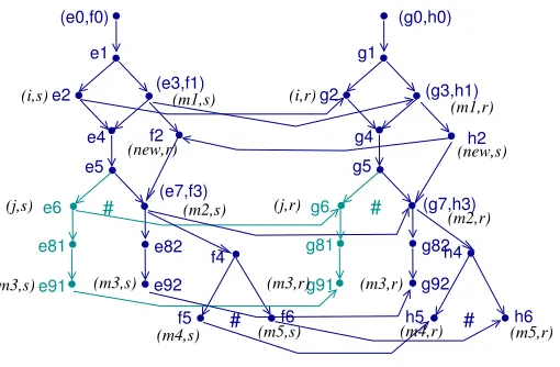
Fig. 4.Matched composition model.
{(e1, e2)|(L(e1), L(e2))∈∆}∪
{(e1, e2)|(e1∈↓Evi1, e2∈↓Evi2 and (i1, i2)∈∆)}
The labels are unchanged, that is, µ(e) = µi(e) for e ∈ Evi withi ∈ {1,2} and
µ(e1, e2) =µ1(e1) =µ2(e2). Event relations inM∆are derived from the relations in
M1andM2as follows(e1, e2)→∗eiff(e1→∗1 eore2→∗2 e);ei→e0iiffei →∗i e0i;
and (e1, e2) →∗ (e01, e02)iff (e1 →∗1 e01 and e2 →∗2 e02). Similarly for the conflict
relation with additional conflict derived from propagation over causality.
According to the above definition, the event pairs (e1, e2) in Ev correspond to events matched by∆ or denoting initial events for shared objects. Relations and la-bels are preserved in the composition as expected.
If the model obtained above is a valid labelled event structure then a composition forSD1andSD2according to∆exists. Otherwise the models are not composable.
Proposition 1 LetM1 = (E1, µ1)andM2 = (E2, µ2)be models for sequence
dia-gramsSD1andSD2, and∆be a matching over instances and labels. The diagrams
arecomposableaccording to∆iff the matched composition modelM∆= (E, µ)is a
well defined labelled event structure.
and any conflict that arises from propagation over the extended causality relation. In this case,e6#(e7, f3)sincee6#e7and consequently alsoe6#f4, and so on.
We want to allow a designer to add further constraints on the expected composition by for example specifying behaviour that should never occur (forbidden events) or se-quences of events that must occur in a given order, and so on. This can be seen as a way to give priority to certain specified interactions, and eliminates some of the possible traces in the composed model.
In the following, letM1 = (E1, µ1)andM2 = (E2, µ2)be composable models over∆for sequence diagramsSD1 andSD2with∆a matching over labels and in-stances. LetM∆= (E, µ)be the matched composed model obtained, andΓ be the set of maximal configurations (traces) inM∆.
Definition 5 Abehavioural glueforM∆= (E, µ)is given byG= (Evg,→∗g,#g, F vg)
whereEvg, F vg⊆Evare subsets of events that occur inE, and→∗g,#g⊆Evg×Evg
are binary relations (causality and conflict) defined over the events inEvg. Events in
F vare forbidden events.
A behavioural glueGas defined above may contain relations over events which disagree with the relations inM∆. However, we can always obtain an equivalent glue
G0that preserves the relations inM∆= (E, µ)by considering all the events that violate the original relations as forbidden events. We omit a formal proof here, but illustrate the idea with an example.
Definition 6 A composed modelSD1kGSD2for relation preserving glueGis given
byMG= (EG, µG)such that it corresponds toM∆by removing all tracest∈Γ such
thatF v∩t6=∅.
Consider the two cases of behavioural glue as shown in Fig. 5. The behavioural glueG1imposes that the occurrence of messagejis forbidden in the composed model. GlueG2imposes that form3to occur,m2must have happened before.
neg
a:A b:B
sdG1
j
G2
a:A b:B
m3 m2 sd
Fig. 5.Examples of behavioural glue.
ForG1we haveG1 = (∅,∅,∅,{e6, g6}) where the events associated to messagej
are forbidden. This means that the com-posed model for sd1 andsd2 wrt G1
removes all traces which contain events
e6 and g6 from the matched composi-tion model shown in Fig. 4. Since the events in ↓ e5 (and similarly ↓ g5) be-long to another valid trace they are not removed. We obtain a composed model which is identical to the matched compo-sition model but where the highlighted relations and events have been removed (i.e., eventse6, e81, e91, g6, g81, g91and relations).
ForG2we consider an equivalent glue which preserves the relations, namelyG2=
(Evg2,→∗g2,∅, F vg2)whereEvg2 ={(e7, f3),(g7, h3), e92, g92},F vg2={e91, g91} and the causality relation is such that→∗
case we need to remove all traces which containe91andg91from the matched com-position model shown in Figure 4. The composed model for sd1and sd2wrt G2
coincides with the composed model wrtG1described earlier. This follows because the traces affected by the forbidden events are the same. We show how the model is gener-ated automatically with Alloy in the next section.
6
Composition with Alloy
We describe how the formal composition semantics from the previous section is inte-grated in ourSD2Alloyapproach. We capture the syntactic matching of labels and in-stances (given by∆in Section 5) by additional axioms (facts). The following describes the syntactic matching of labels and instances (lifelines) for our example.
fact LifelineMatching{
//matching lifelines from sd1 and sd2
all l1:sd1_L1, l2:sd2_L2 |
(l1.name=l2.name && l1.class=l2.class) => #l2=0 }
fact MessageMatching{
//matching message sd1_m1 and sd2_m1
all m:sd1_m1, n: sd2_m1 |
(m.name=n.name) => #n=0 and #sd2_e3=0 and #sd2_g3=0
//matching message sd1_m2 and sd2_m2
all m:sd1_m2, n:sd2_m2 |
(m.name =n.name) => #n= 0 and #sd2_e7=0 and #sd2_g7=0 }
The factLifelineMatchingmatches the shared lifelines in both diagrams, and the factMessageMatchingmatches the messages with the same name. The idea in Alloy is that the messages and events from one of the models are kept (heresd1) and the others are hidden by limiting its occurrence to zero (i.e., its cardinality is zero).
The examples of behavioural glue introduced in Fig. 5 can be captured as facts in Alloy.G1andG2are given in the following facts.
fact Glue1{#sd1_j=0
all sd1_j_send:sd1_e6, sd1_j_receive:sd1_g6 | #sd1_j_send=0 and #sd1_j_receive=0}
fact Glue2{ #sd1_m3=#sd1_m2
all sd1_m2_send:sd1_e7, sd1_m3_send:sd1_e9 | sd1_m3_send in sd1_m2_send.ˆnext
all sd1_m2_receive:sd1_g7, sd1_m3_receive:sd1_g9 | sd1_m3_receive insd1_m2_receive.ˆnext
}
Glue1states thatjdoes not occur and in addition the associated events also do not occur.Glue2states that every timem3occurs it must occur withm2. In other words,m2
must have happened before. Again, we control occurrence with the cardinality operator
#. In addition, the behavioural glue forG2also defines the order betweenm3andm2
and underlying send and receive events.
does not occur in any solution obtained. Traces obtained with our tool have a direct correspondence with the traces of our semantic model.
7
Related work
Zhang et al. [23] and Rubin et al. [19] use Alloy for the composition of class diagrams. They transform UML class diagrams into Alloy and compose them automatically. They focus on composing static models and the composition code is produced manually. Widl et al. [21] deal with composing concurrently evolved sequence diagrams in accordance to the overall behaviour given in state machine models. They make direct use of SAT-solvers for the composition. Liang et al. [15] present a method of integrating sequence diagrams based on the formalisation of sequence diagrams as typed graphs. Both these papers focus on less complex structures. For example, they do not deal with combined fragments which can potentially cause substantial complexity.
Composition is also important in other domains such as aspect-oriented modelling. Whittle and Jayaraman [3] introduce a tool called MATA for weaving based on se-quence diagrams. They put less emphasis on the semantics of the composition. Grønmo et al. [10] propose a semantics-based technique for weaving behavioural aspects into sequence diagrams. The example we use in this paper is an adaptation of the exam-ple introduced there. However, we have a true-concurrent semantics and consider and treat parallelism in interactions. In subsequent work, Grønmo et al. [9] propose the con-formance issue for aspects in ensuring that the woven always leads to the same result regardless of the order in which aspects are applied. When looking at the integration of several model views or diagrams, Bowles and Bordbar [6] present a method of mapping a design consisting of class diagrams, OCL constraints and sequence diagrams into a mathematical model for detecting and analysing inconsistencies.
Checkik et al. [7] identify model integration operators, such as merge, weave, and composition, and describe each operator along with its applicability. In addition, they provide a set of desirable criteria (completeness, non-redundancy, minimality, totality, soundness) to evaluate the merge operator. This is a direction orthogonal to our research and remains an area for future investigation.
8
Conclusion
To ensure correctness of the composition process, we have formalised the semantics of the composition with the help of labelled event structures. The result obtained auto-matically with Alloy preserves our formal interpretation of parallel composition with synchronisation glue. Our Alloy-based automated method of composition has been im-plemented as an Eclipse plugin for the composition of sequence diagrams. Throughout the paper a small example of composing sequence diagrams inspired by an example from [10] related to weaving aspects is used.
References
1. Allen, R., Garlan, D.: Formalizing architectural connection. In: ICSE 1994. pp. 71–80. IEEE Computer Society Press (1994)
2. Alwanain, M., Bordbar, B., Bowles, J.: Automated composition of sequence diagrams via alloy. In: Pires, L., Hammoudi, S., Filipe, J., das Neves, R. (eds.) MODELSWARD 2014. pp. 384–391. SciTePress (2014)
3. Ara´ujo, J., Whittle, J.: Aspect-oriented compositions for dynamic behavior models. In: Mor-eira, A., Chitchyan, R., Ara´ujo, J., Rashid, A. (eds.) Aspect-Oriented Requirements Engi-neering, pp. 45–60. Springer (2013)
4. Ara´ujo, J., Whittle, J., Kim, D.: Modeling and composing scenario-based requirements with aspects. In: RE 2004. pp. 58–67. IEEE Computer Society Press (2004)
5. Berre, D.L., Parrain, A.: The SAT4j library, release 2.2 - system description. Journal on Satisfiability, Boolean Modeling and Computation 7, 59–64 (2010)
6. Bowles, J., Bordbar, B.: A formal model for integrating multiple views. In: ACSD 2007. pp. 71–79. IEEE Computer Society Press (2007)
7. Chechik, M., Nejati, S., Sabetzadeh, M.: A relationship-based approach to model integration. Innovations in Systems and Software Engineering 8(1), 3–18 (2012)
8. Fiadeiro, J., Lopes, A., Wermelinger, M.: A mathematical semantics for architectural con-nectors. In: Backhouse, R., Gibbons, J. (eds.) Generic Programming, LNCS, vol. 2793, pp. 178–221. Springer (2003)
9. Grønmo, R., Runde, R., Møller-Pedersen, B.: Confluence of aspects for sequence diagrams. Software & Systems Modeling 12(4), 789–824 (2013)
10. Grønmo, R., Sørensen, F., Møller-Pedersen, B., Krogdahl, S.: Semantics-based weaving of uml sequence diagrams. In: Vallecillo, A., Gray, J., Pierantonio, A. (eds.) ICMT 2008, LNCS, vol. 5063, pp. 122–136. Springer (2008)
11. Harel, D., Marelly, R.: Come, Let’s Play: Scenario-based Programming Using LSCs and the Play-Engine. Springer (2003)
12. Jackson, D.: Software Abstractions: logic, language and analysis. MIT Press (2006) 13. Klein, J., H´elou¨et, L., J´ez´equel, J.: Semantic-based weaving of scenarios. In: AOSD’06. pp.
27–38. ACM (2006)
14. K¨uster-Filipe, J.: Modelling concurrent interactions. Theoretical Computer Science 351, 203–220 (2006)
15. Liang, H., Diskin, Z., Dingel, J., Posse, E.: A general approach for scenario integration. In: MoDELS 2008. pp. 204–218. LNCS 5301, Springer (2008)
16. Micskei, Z., Waeselynck, H.: The many meanings of UML 2 sequence diagrams: a survey. Software and Systems Modeling 10, 489–514 (2011)
17. OMG: UML: Superstructure. Version 2.4.1. OMG, http://www.omg.org. (2011), http://www.omg.org, document id: formal/2011-08-06. [accessed 1-6-2012]
19. Rubin, J., Chechik, M., Easterbrook, S.: Declarative approach for model composition. In: MiSE 2008. pp. 7–14. ACM (2008)
20. Whittle, J., Ara´ujo, J., Moreira, A.: Composing aspect models with graph transformations. In: Proceedings of the 2006 international workshop on Early aspects at ICSE. pp. 59–65. ACM (2006)
21. Widl, M., Biere, A., Brosch, P., Egly, U., Heule, M., Kappel, G., Seidl, M., Tompits, H.: Guided merging of sequence diagrams. In: SLE 2012. pp. 164–183. LNCS 7745, Springer (2013)
22. Winskel, G., Nielsen, M.: Models for Concurrency. In: Abramsky, S., Gabbay, D., Maibaum, T. (eds.) Handbook of Logic in Computer Science, Vol. 4, Semantic Modelling, pp. 1–148. Oxford Science Publications (1995)