warwick.ac.uk/lib-publications
A Thesis Submitted for the Degree of PhD at the University of Warwick
Permanent WRAP URL:
http://wrap.warwick.ac.uk/78842
Copyright and reuse:
This thesis is made available online and is protected by original copyright. Please scroll down to view the document itself.
Please refer to the repository record for this item for information to help you to cite it. Our policy information is available from the repository home page.
Improvement of Product Development Cycle Time
and Cost by applying Concurrent Integrated
Design and Assembly Planning
by
Research Engineer Tat Lun Ng
MBE, JP. MSc(Eng), MBA, CEng, RPEng,FlEE, FIMechE, FIMfgE, FIMgt, FHKIE, Sr. MIlE, Sr.MSME, VDI,
An Eng.D Portfolio
submitted in fulfilment of the requirements for
the award of Engineering Doctorate
of The University of Warwick
Department of Engineering
I,
Tat Lun Ng, hereby declare that this Eng.D portfolio, entitled
"Improvement on product development cycle time and cost
by
applying
Concurrent Integrated Design and Assembly Planning" , which I am
submitting, represents my own work and has not been previously
submitted to this or any other institution in the application for admission to
a degree, a diploma or any other qualifications.
Signed :, _ _ _ _ _ _
_
TatLunNg
Abstract
Sonca is a manufacturing operation producing torches and lanterns. In order for the Company to be competitive, one of the key factors is to introduce new products to market quicker and at a lower total product cost. A system titled "concurrent integrated design and assembly planning (CIDAP)" is developed to aid this process.
It is identified that methods proposed by other researchers using different algorithms are not interactive enough and need too much space to store the representation of assembly sequences and time to process the assembly operations for a complex assembly. Besides, the commercially available systems and software are not integrated and are too universal. The data used is not compatible with the company's data file.
The CIDAP framework focuses on concurrent and integration, in that the different processes in the whole product development cycle are carried out concurrently and are integrated. In the framework two techniques, namely KALG (Knowledge-based Assembly Liaison Graph) and KPN (Knowledge-based Petri Net) and four expert systems for selection of assembly system, feeder, gripper, and sensing technology are developed. Commercially available software such as Boothroyd and Dewhurst's DFMA (Design For Manufacture and Assembly) software, Rapid Prototyping and Quick Tooling are also applied in the framework
The frame work and the systems are applied to an actual case in designing a series of torches within the Company. Results show that the product development cycle time is improved by 25%, rework cost reduced by 20%, and final product cost reduced by 11 %. The Company has adopted the new framework.
Executive Summary
Contents
Glossary
3
1
Introduction 52 Recent development on design and assembly planning
9
3
Literature review13
3.1
assembly modelling13
3.2
Assembly system15
3.3
Petri Net based assembly and disassembly planning16
4 Ideas developed in the Project
17
4.1
Concept of Concurrent Integrated Design and Assembly Planning17
4.2
Product design for assembly19
4.3
Assembly planning21
4.4
Knowledge-based Assembly Liaison Graph (KALG)22
4.5
Knowledge-based Petri net (KPN)23
4.6
Flexible assembly system24
4.7
Tool Kit, CIDAP Expert System (TKIT-CIDAPES)24
5 Application of developed model to live cases
25
5.1
Design objective25
5.2
Work involved26
5.3
Results29
6 Achievement/Innovation
31
7
Conclusion33
7.1
Application of CIDAP within the Company33
7.2
Application of CIDAP outside the Company35
7.3
Future work36
8 References
37
ALG AOPC AutoCad BDI CAAPP CAD CE CIDAP DFA DFM DFMA ES·ASS ES·FS ES·GS ES·STS FAS H230 H300 H500
Glossary
Assembly Liaison Graph
Assembly Operations Process Chart
It is a computer-aided design software tool developed by
AUTODESK used to speed up repetitive drawing tasks and
simplify drawing revisions.
Boothroyd and Dewhurst, Inc.
Computer Aided Assembly Process Planning
Computer Aided Design
Concurrent Engineering
Concurrent Integrated Design and Assembly Planning
Design For Assembly
Design For Manufacture
Design For Manufacture and Assembly
Expert System for Assembly System Selection
Expert System for Feeder Selection
Expert System for Gripper Selection
Expert System for Sensing Technology Selection
Flexible Assembly System
A two R14 cells torch with small size lens-ring
A two R20 cells torch with regular size lens-ring
H550 IDAP IGDS KALG KPN OEM PBS PDS
Petri Net (PN)
Pro-Engineer
QT
RP
The Company
TKIT-CIDAPES
A three R20 cells torch with large size lens-ring
"Integrated Design and Assembly Planning" by H. J. Bullinger
and M. Richter
Integrated Graduate Development Scheme of the University of
Warwick
Knowledge-based Assembly Liaison Graph
Knowledge-based Petri Net
Original Equipment Manufacturer
Push button switch
Product Design Specification
A net-theoretic approach developed by Carl A. Petri in 1962 to
model and analyse complex communication systems by
capturing the precedence relations and structural interactions of
stochastic, concurrent and asynchronous events.
It is a software tool developed by Parametric Technology
Corporation used to automate the mechanical development of a
product from its conceptual design through its release into
manufacturing.
Quick Tooling
Rapid Proto typing
Sonca Products Limited
Tool Kit, Concurrent Integrated Design and Assembly Planning
1.
Introduction
The Research Engineer works in Sonca Products Limited (the Company) as
managing director. He joined the Company in 1965 as a mechanical engineer.
The Company is a multi product company set up in Hong Kong in 1953. In 1996,
it had headquarters situated in Hong Kong and two factory plants, one in Pearl
River Delta of China, and the other in Macau. The headquarters has a floor area
of 3,600 square metres and employs around 180 employees. It houses all
functional departments excluding the manufacturing operations. The plant in
China has a production floor area of 35,000 square metres. The whole campus for
the production facility, the dormitories, and amenities has a site area of around
60,000 square metres. The number of employees is around 2,200. The branch
factory in Macau is much smaller in size. Its production floor is 5,000 square
metres housing around 150 employee.
The company is the most vertically integrated operation in the field of torches and
lantern manufacturing. It has its own industrial design, engineering design,
manufacturing and process design, marketing and sales, inbound and outbound
logistics, and of course, finance and human resources functions The
manufacturing also covers the full spectrum of operations including its own metal
forming, plastic injection moulding, plastic blow moulding, surface finishing
and electrostatic spraying), assembly and packing. Apart from having its own
in-house industrial design of the products, the Company works with two outside
design consultants, one in the USA, and the other in Australia.
Since the start of the Company, it has stuck to a policy of producing products
designed in-house for the world market using the Company's own brand name
"SONCA". As such, product development is one of the important functions of the
Company. For the past forty odd years, the Company underwent evolutionary
changes in its approach in product development. The first approach which took
place from 1953 to 1963 was the vertically integrated approach, in which the
design and development of the product from the beginning to the end was done by
one man with the various functions integrated vertically. The functions included
product conceptual design, detail engineering design of the product, the design of
the production processes, design of the assembly operation sequences, and the
design/fabrication of special machines for torch manufacture.
The second phase was the functional department approach. It adopted the
principle of specialisation. The design department was split into three
departments, namely, the industrial design department, the product engineering
department, and the industrial engineering department. Co-ordination of these
three departments was carried out by the development manager in charge of the
three departments. This was satisfactory given that the scope of the Company at
that time was still of medium size, and that information technology was not so
The third phase was the TQM approach. This took place from 1986 to the present
day. Product design and development is no longer the sole responsibility of the
industrial design and the product development department. It is co-ordinated by a
committee. There are four interim monitoring teams to help co-ordinate the cross
departmental functionalities. This has proved to be very successful.
In the existing system using the TQM approach, the average product development
cycle time is eight months. Close analysis reveals that about two to three months
time was spent on the rework of the product design and modifying tooling after
the first pilot run. In the competitive world of today, such a long product
development cycle time and high rework cost is definitely not desirable. The
Research Engineer believes that while the approach is a good one in terms of
human aspects where all resources are pulled together by better co-ordination
among all concerned departments, any break through would be in the technical
aspects. This was the initiative behind this Project.
It is the Company's strategy to reduce the product development cycle time and
the rework and the development cost. The Company employs a development
manager reporting to the Research Engineer. In February 1994, the development
manager resigned from the Company of his own accord. The Research Engineer
decided to leave the post vacant until a suitable candidate could be found, rather
than to fill the post by someone marginally capable for the job. In the mean time,
the Research Engineer took on the job on top of his being the managing director.
the Research Engineer wanted to spend time to develop a new system to improve
the whole product development cycle and cost.
The objective, as detailed in Section 1.2.3 of the portfolio, was to research into
the latest development on design and planning for assembly, and to develop a new
system suitable for the Company and the light industry in Hong Kong using the
concurrent and integrated approach aiming to:
- Shorten the product development cycle time to less than six months,
- reduce the rework in design and tool modification, and
- reduce the total product development cost.
The title of the Project is "IMPROVEMENT OF PRODUCT DEVELOPMENT
CYCLE TIME AND COST BY APPLYING CONCURRENT INTEGRATED
DESIGN AND ASSEMBLY PLANNING (CIDAP)".
The Company intended to introduce to the market a family of four waterproof
torches, which would consist of: one two R20 cells torch with regular size
lens-ring (H300); one three R20 cells torch with regular size lens-lens-ring (H500); one
three R20 cells torch with large size lens-ring (H550); and one two R14 cells
torch with small size lens-ring (H230). The plan was to introduce the first two
models to the market first. Pending good response from the market, the other two
models would be introduced. It was estimated that the family of torches would
have a product life of at least five years, and the average annual sales would be
same engineering design but with different sizes. They would use a common push
button switch which was a standard product manufactured in the Company.
As for the switch, the Company produced a family of eight types of push button
switches, namely PBS-l to PBS-So They all have common parts except the
contactor used to make contact with the torch bodies. The idea of the exercise
was (i) to review the design of the switch for assembly cost improvement, and (ii)
to determine the optimum assembly system for them, i.e., whether by bench
manual assembly, dedicated assembly or flexible assembly. The annual quantity
requirement would be ten million pieces including those for resale as OEM items.
2.
Recent development on design and assembly planning
As discussed in Section 1.3 of the portfolio, the traditional product-process
method as suggested by Nevis and Whitney (1) is sequential. It does not take into
account the liaison of each design activity. Therefore the process is costly,
tedious, and does not help in optimising the product design and production. To
solve the problem, many researchers looked "into the concurrent and integrated
product design approach. It means that the product design and its manufacturing
system are considered and carried out concurrently and integrated so as to obtain
Research also revealed that assembly has traditionally been one of the highest
areas of direct labour costs. In some cases, assembly accounts for 50% or more of
manufacturing costs and is typically at 20-50%. Since assembly is an important
field influencing product manufacturing costs, most research work concentrates
on the design for manufacture and assembly. The common approaches used are
concurrent engineering (CE), design for assembly (DFA) [21 , design for
manufacture (DFM) [31 , integration of product design with assembly process
planning, (IDAP) [41 , generation and choice of assembly plans, flexible assembly
system modelling and simulation, etc.
The choice of the assembly sequence affects the efficiency of the assembly
process. Traditionally, the product assembly sequence was planned by an
experienced production engineer. However, the planning of assembly sequences is
a trivial and error-prone task because there m~y exist a large number of potential
assembly sequences in a complex assembly especially in a flexible one and in
concurrent engineering environments.
Many research activities have focused on various aspects of assembly sequence
planning such as assembly modelling, assembly sequence representation, assembly
sequence generation algorithm, etc. However, these methods can only represent
partial assembly precedence knowledge. Homen De Mello and
Sanderson[SI proposed an AND/OR graph representation of all the possible
using disassembly or decomposition method based on the assumption that the
disassembly sequence is the reverse of a feasible assembly sequence.
/ "
There are methods proposed by other researchers using different algorithms as
detailed in Section 1.4 of the portfolio. These methods and algorithms are less
interactive and need much more space to store the representation of assembly
sequences and processing time to process the assembly operations for a complex
assembly.
In reviewing the work done by many researchers, the Research Engineer identified
the following deficiencies:
• The systems are not integrated
Most of the developed systems concentrat.e in a special area. For example,
DFMA of BDI is for the review of the design of parts relating to
manufacturability and assemblability; AND/OR graph is for the presentation of
the assembly sequence. They lack a concurrent and integrated approach to the
problem.
• The systems are too universal
The systems are designed for general use. While they are comprehensive to
cover different designs of products, they become too broad for a specific field.
In using these systems, the Company finds that it takes much time to find the
Company to develop its own expert system based on its own experience to
speed up the process in actual application.
• Data are not compatible
This is the corollary of the above point. To build up the Company's own data
file and expert system would greatly help reduce the processing time in applying
the system as the data are compatible.
• The systems may not be applicable to small and medium size companies
The concurrent integrated product design systems developed by previous
researchers are mainly for large companies. Their success is dependent on a
team-based working environment and on the aid of practical support tools.
These companies have enough capital to develop their specific design tools and
enough technologists and technicians to d~velop new techniques. They have
powerful design teams to develop new products. For small and medium size
companies, because of the lack of design teams, certain decisions can not be
made until others have been made. This limits the operation of integrated
product design in parallel. On the other hand, they, having fewer designers, do
not have the difficulty of co-ordinating the activities among themselves. Small or
medium size companies need to respond quickly to market changes to achieve
commercial success. They seldom develop new processes and techniques, but
rather acquire them to their operations. These may be the major differences
between small and large companies. The concurrent integrated design and
well as for the small and medium size comparues in Hong Kong's light
industries. It will use a quantitative and axiomatic method. Some existing
technologies and computer-aided tools are used in implementing the
methodology.
To overcome the above drawbacks, the Research Engineer decided to develop a
concurrent and integrated design and assembly planning approach suitable for
the Company and the light manufacturing industry in Hong Kong.
3. Literature review
3.1 Assembly modelling
The Research Engineer studied the assembly process suggested by
Rampersadl61• It showed that assembly by means of material flows is linked to
the parts manufacturing, and that by means of information flow it is integrated
with marketing, product planning, product development, process planning,
and production control. To understand the interaction between the various
assembly variables is very important in the analysis and design of assembly
systems, as well as in the product development and process planning. In order
to realise a controllable design process and a high design quality, an integral
assembly model is presented. It attempts to improve the insight into the
suggested by Rampersad is shown below and detailed in Section 2.1.1 of the
portfolio.
Fig. 1 An integral assembly model [Rampersad 94]
Rampersad discussed in detail the three relationships between (i) product
assortment, assembly strategy and system layout; (ii) product structure,
assembly structure and system structure; and (iii) product component,
assembly operation and system components.
In assembly modelling, the most common method used to model mechanical
parts is the geometric database of CAD systems. The liaison graph and its
matrix representation show the relationship between two components. It can
be implemented by the total relative constraints which can be extracted from
the CAD drawing. The assembly liaison relationship of a product can be
[image:17.506.178.378.78.320.2]2.1.4 of the portfolio. Based on this graphic presentation, a knowledge-based
assembly liaison graph is developed.
There are three main approaches to the representation of assemblies such as
language-based, graph-based and advance data structure representation. In
this project, the AND/OR graph is used to represent the assembly sequence.
3.2 Assembly system
The two basic classes of assembly system are those performed by people
(manual assembly) and those by mechanisms (automatic assembly). Manual
assembly has two forms, namely bench and line manual assembly. Automatic
assembly also divides conveniently into two categories, namely dedicated
and flexible assembly.
For flexible assembly, the following areas were reviewed; design for robot
assembly, specific assembly operation theories, axiomatic approaches,
unstructured DFA rules and concepts, procedural methods,
expert/knowledge-based systems, sensors, programming, languages, and off-line programming.
In order to facilitate an easy reference to pick the right feeder, gripper, and
sensing technology, this Project suggested three expert systems based on the
3.3 Petri Net based assembly and disassembly planning
In recent years, with the rapid development of F AS (flexible assembly system),
much research work has focused on the development of an intelligent robot
flexible assembly planning system which is one of the important parts of F AS.
In research done by Zhang in 1989 (8) , Petri Net is applied to assembly. In his
paper, Zhang presented an approach to model assembly and an algorithm to
automatically derive the operation sequence by utilising Petri net model of
assembly, while the goal and constraints are only specified. The representation
of assembly in the form of Petri net produces an overall model of the goals
which are to be achieved, the initial resource constraints and dynamic features
of assembly. Based on the Petri net representation, the plan generation is quite
straight forward and can be easily implemented with a simple matrix
calculation. Details of Zhang's model ar~. highlighted in Section 2.4 of the
portfolio.
The model is a good approach to represent all the feasible assemblies, but
lacks the ability to choose the best assembly sequence. In this Project, the
Research Engineer, based on Zhang's approach, developed the
knowledge-based Petri net. It supplements Zhang's model in that it introduces the flow
4. Ideas developed in the Project
4.1 Concept of Concurrent Integrated Design and Assembly Planning
There are many sophisticated procedures in product design and assembly
system development. It needs many aspects of knowledge and experience, and
requires team work. The sequential approach currently used in product design
and assembly system development is not effective. It does not help in
optimising the design of the product and assembly system. In order to obtain
an economically viable design and assembly system for flexible assembly,
product design and assembly process planning must be integrated and
considered concurrently.
..
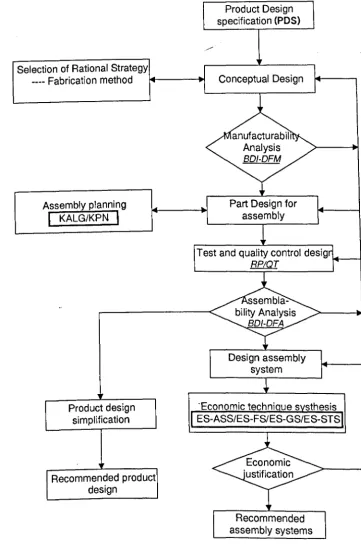
In Concurrent Integrated Design and Assembly Planning (CIDAP) as detailed
in Chapter 3 of the portfolio, the product development process is divided into
five stages. They are: conceptual design, assemblability analysis & detail
design, assembly system design, assembly planning and simulation, and
economic justification. They are carried out concurrently and are integrated.
The analysis of manufacturability and assemblability, the detail engineering
design of the parts, and the selection of assembly system and assembly
sequencing will be iterated until the optimal design is achieved.
Product Design specification (PDS)
Selection of Rational Strategy
____ Fabrication method 1+---.1
Assembly planning
I
KALG/KPNI
Product design simplification
Recommended product design
Test and quality control desig
RPIQT
Fig. 2 Concurrent Integrated Design and Assembly Planning Flow chart
BDI-DFM BDI-DFA ES-ASS ES-FS ES-GS ES-STS KALG KPN RP QT
means BDI's Design For Manufacture means BDI's Design For Assembly
means Expert System For Assembly System Selection (Self- developed) means Expert System For Feeder Selection (Self-developed) means Expert System For Gripper Selection (Self-developed) means Expert System For Sensor Technology Selection (Self-developed) means Knowledge-based Liaison Graph (Self-developed) means Knowledge-based Petri Net (Self-developed) means Rapid Prototyping
[image:21.508.104.465.29.575.2]Before product design, the product specifications must be identified and
documented. Section 4.1 of the portfolio discussed in detail the Product
Design Specification (PDS) , which is a document that contains all the
requirements relating to the product outcome. It is the basic reference and the
control for all design activities. It should be kept in mind that though PDS
should be static at all times, it can however be subject to change if the
specification of the product is out of reach of the most economical way of
manufacture and assembly, or is not meeting the customers' requirement.
When it comes for review, full investigation into the reasons why it needs to
be changed should be carried out. In defining the PDS, non-manufacturing
factors such as marketing, finance, material supply etc. should be considered
as well. However these factors are beyond the scope of this Project.
4.2 Product design for a.~sembly
In the design of a product, there are the following phases.
• Conceptual design
Conceptual design is referred to as a phase in design activities in which many
alternative concepts are generated to comply with the requirements of the
PDS. Conceptual design converts the PDS into a manufacturable and
saleable product concept by clearly articulating all the associated goals,
• Constitution analysis of product
This involves the design of the parts and/or sub-assemblies to form the
/ '
hierarchical structure of the product. Its goal is to find out the number of
components, product structure, the common and non common components,
and standard and non standard components .
• Consideration for manufacturability and assemblability
In this phase, designers should consider by which method the product should
be fabricated and assembled. The Research Engineer adopted the BDI's
(Boothroyd and Dewhurst) DFMA software (9) •
• Selection of assembly systems
Product design including its part design depends highly on the assembly
system to be used later. In this phase, HQI's software can be used to select
the system of assembly. It contains a host of detail rules and strategies. In
this project, an intelligent approach which employs simple cost estimating
algorithms and expert system to perform the necessary ranking and decision
making in terms of cost in concurrent product design is presented .
• Material selection and fabrication method
The choice of material can be referred to relevant manuals or handbooks.
However, it is not an ideal method for the systematic selection of suitable
• Detailed design
It includes calculation of design parameters, selection of material and
.~/
fabrication method, determination of shapes, dimensions, and tolerances of
product and its components etc. The Company uses AutoCad and
Pro-Engineer. They are powerful tools and have interactive functions in editing
graphics and drawings.
• The software
As mentioned earlier, part design for assembly has a close relationship with
the assembly system to be used. Based on Lourdes[lO] , this Project has
initially implemented the integration between CAD and DFA analysis by two
computer algorithms to calculate the overall dimensions and rotational
symmetries of part data which are called DIMENSION and SYMMETRY
respectively. The development of the abov~ two algorithms, as detailed in
Section 4.4.3 of the portfolio, is still at a very primitive stage in the
Company. Unfortunately the technician who wrote the software left the
Company to emigrate to Singapore, thus bringing the work to a temporary
halt. Future work in this area will be carried on.
4.3 Assembly planning
Assembly planning refers to the generation and choice of assembly plans and
components or sub-assemblies are put together in the mechanical assembly of
a product can drastically affect the efficiency of the assembly process. It was
--mentioned earlier that the product assembly sequence is traditionally planned
by an experienced production engineer. It is time consuming and error-prone.
There is a growing need to systematise and to computerise the generation of
assembly sequences.
In this Project, focuses are put on the approach and the system for automatic
generation of assembly sequences. They are key issues of computer aided
assembly process planning (CAAPP). A new representation of product
assembly relationship and assembly constraints and a methodology for
generating the detailed feasible sub-assembly sets of assembly plans for a given
product was presented using the technique of KALG (knowledge-based
Assembly Liaison Graph).
4.4 Knowledge-based Assembly Liaison Graph (KALG)
In 3.1 above, it was mentioned that one of the powerful tools in the design of
assembly sequence is the Assembly Liaison·Graph (ALG). It is a graphical
representation showing all the relationships of the different parts of the
designed product. Again it lacks the ability to identify the unfeasible
assemblies, resulting in a very large and complicated graph. This Project
introduced the Knowledge-based Liaison Graph (KALG). The idea, as
gained within the Company to develop an expert system of basic rules and
constraints to find out the unfeasible assemblies. By eliminating them, the
~
feasible assemblies can be obtained. It reduces the time and effort in the
assembly planning process.
To generate assembly or disassembly sequences automatically, an automatic
knowledge inferring system is introduced to solve this problem. The
programme is written in artificial intelligence language Turbo-prolog 2.0. All
feasible sub-assemblies are generated by automatic inference and classification
when the user answers questions about the assembly facts and information
presented by the system. Alternatively the user can input the assembly
knowledge-base file. The programme was still at a primitive stage. More work
will be done in the future to debug and simplify it. Though the expert systems
are developed for the Company, they may
be
useful to other industries of similar nature of production system and products.4.5 Knowledge-based Petri net (KPN)
In the planning of a flexible assembly system Zhang[S) suggested the Petri net
approach. In Section 5.5 of the portfolio, a knowledge-based Petri net was
developed as an extension of Zhang's basic Petri net model. The central idea
is to introduce the flow control Fe, which describes the knowledge of selecting
the sub-assembly sequence with the minimum sub-assembly time. An
4.6 Flexible assembly system
A critical step in the design of flexible assembly systems is the selection of
feasible technologies in order to perform the required tasks cost-effectively.
People are the most flexible assemblers and most dextrous, but their
performance varies, and is difficult to be documented and held to a standard.
A flexible assembly system is composed of some programmable robots and
part handling devices. It offers an alternative combining the flexibility of
people and the uniform performance of fixed automation. Therefore it meets
the needs of various products in small to medium batch production.
In the area of design for flexible assembly, the Research Engineer developed
the Assembly Operation Process Chart (AOPC) which is a part tree
representation of the assembly sequence. In order to have a quick selection of
the feeders, grippers and sensing technologies for the flexible assembly system,
three expert systems were introduced. These systems were developed based
on the experience within the Company. They are fully presented in Chapter 6
of the portfolio.
4.7 Tool Kit, CIDAP Expert System (TKIT·CIDAPES)
There IS commercial available software in the market to aid the
implementation of the computer-aided design and assembly planning. The
because of two reasons. The first is that they are mostly not integrated. The
second is because they are designed for general use and may not be too ,~
efficient ( in terms of quick reference) for the Company which produces one
quite homogeneous product, such as a torch. As such, the Research Engineer
developed a prototype expert system TKIT -CIDAPES (Tool Kit, CIDAP
Expert System) as detailed in chapter 7 of the portfolio. A summary of the
Tool Kit is shown below. Those expert systems and software in the bold line
boxes were developed by the Research Engineer.
Design for Manufacture Assembly Planning and Assembly
Product Design
~
Assembly
I
Assembly Process Planning and SimulationI
SystemDesign
CAD and Drawing
(2D-3D) Geometry
I
Features PN!& KPN A Nn/()R Assembly AssemblyForAuto Calculation Assembly Assembly Process Equipment System Sequence
l
Planning ~ Generation Layout & SelectionDFA Simulation
Analysis and Evaluation
5. Application of developed model to live cases
5.1 Design objective
a family of four waterproof torches, the H-series. They will use a common
push button switch which was a standard product manufactured in the
Company. As for the switch, the Company produced a family of eight types of
push button switches, the PBS-series They all have common parts except the
contactor which is used to make contact with the torch bodies. The idea of the
exercise was (i) to review the design of the switch for assembly cost
improvement, and (ii) to determine the optimum assembly system for them.
The characteristics of a torch are variants and small to medium batch. The
types of products are often changed according to the market requirements.
The most important one for design and manufacturing is the appearance
design. It must be appealing in aesthetics and ergonomics. From a marketing
point of view, it is desirable to have a family of torches and to introduce them
to the market together instead of introducing one single model at one time.
This helps to promote sales and can aim for different segment of the market
including men, women, and children.
5.2 Work involved
Details of the work involved is described in Chapter 8 of the portfolio. The
following summarises the work done.
The Product Design Specification was first prepared, based on which, the
expert system and BDI were used to select the most economical assembly
system. It was suggested that a special purpose free transfer system would be
the preferred one. Thereafter followed the detail design and part design. In
doing so the DFMA system of BDI was employed. A bill of material was then
generated.
In assembly planning, the KALG technique together with the developed
software was employed to find the feasible assembly sequences. This is
applicable to both assembly by manual assembly and flexible assembly. The
assembly processes for the torch and the switch were shown using the
AND/OR representation, and the assembly sequences using the AOPC
(Assembly Operation Process Chart). Finally, by applying the KPN
(Knowledge-based Petri net) technique developed in the Project, the optimum
assembly sequence was determined.
I t was identified that a flexible assembly system is the most economical system
for the assembly of the torch H-series and the switch PBS-series because of
two reasons. The first reason is the family approach of both the torch and the
switch in that each of the family of products are basically of the same
construction with only slight variation in size. The switch PBS-series has eight
versions, and the only difference is the contact strip which makes contact with
the tube of the torch. The second reason is the economy of scale which is the
The Company however decides to defer the adoption of the recommended
flexible assembly system to a later date, and to adopt the manual assembly
system with the recommended assembly operation sequence. The Company
considered the investment of the project both in hardware and software in
terms of human factors. As for the hardware, the Company was convinced
that the investment would pay back in the long term. There would also be the
fringe benefit of consistent quality, higher output, and shorter throughput
time. The Company realises that labour costs will continually go up and if no
automation or mechanisation is implemented, one day the Company will lose
out to the competitors.
It was the software that made the Company hesitate to move ahead with the
recommendation. The Company moved the manufacturing operation to Buji,
China in 1987. In 1990, it expanded and relocated the operation to the present
site in Bogang, China. All the technical staff including engineers, technician
and craftsmen did not have over two years experience in the Company when
the Project was started in 1993. By the time the recommendation was made in
mid 1995, most of the technical people were not yet ready for flexible
assembly using robots. In fact a large proportion of them had no working
experience with robots. In running a robotics flexible assembly system,
technical support in setting up, fine tuning and maintaining the robots are vital
in making the project successful. In the absence of such support, the Research
Engineer decided to defer the introduction. Instead, a manual assembly system
the torches and the switches. The torch H300 and H500 were introduced to
the market in late 1995. The Company will monitor the sales of these two
models. By early 1997, it will decide whether to introduce the other two
models. The introduction of them will add more weight to the scale of
economy in assessing the use of flexible assembly system. By that time, i.e.,
mid 1997, the Company would also be in better position in having sufficient
capable technical staff to set up, run, monitor and maintain the system.
5.3 Re.4iiults
..
Detailed results are presented in Section 8.8 of the portfolio. The following is
the summary.
Most of the parts of the new torch series were new except for some standard
parts. As such they all underwent changes in the design process. The BDI's
DFMA software helped identify deficiencies and recommend changes in the
design of parts. Equally successful was the review of the existing switch.
Based on the recommendation, the family of switches was redesigned and the
unit production cost was lowered by 13%.
Previously the normal product development cycle from approving the
appearance design to the launch of the product was around eight months. The
development cycle time was reduced to only six months, that is a reduction of
25%.
During the whole process, CIDAP framework was applied and the team
approach was practised. It resulted in a reduction of the total cycle time,
mainly in the rework of the design and time saving in performing concurrent
product design, tool design and tool making. The time saving for the former
was about one and half months, while the latter contributed to the other half
month time saving. It was observed that there would have been around 20%
reduction in tool rework cost when gauged by the normal percentage of
"
rework recorded in previous designs.
Other management time spent on the product was also less. Though it was not
formally recorded, it was reported that the overall product development cost
for the Project was less by 23%.
Before the product was approved to go ahead for development, the estimated
unit cost was prepared. When the product was later introduced to the market,
the unit cost was finalised. It was 89% of the estimated one. The saving was in
the two areas of material cost and labour cost. It was brought about by the
better design of the product based on the suggestions of redesign and by the
Apart from the tangible benefits mentioned above, the Research Engineer
observed a higher morale in the organisationvbecause of less rework and
shorter delivery time.
6. Achievement/Innovation
The CIDAP (Concurrent Integrated Design and Assembly Planning) framework is
an integrated system. In the process of product development, the design of the
product, the selection of the assembly system and assembly sequencing are carried
out concurrently and are integrated. The framework has four advantage over those
proposed by other researchers as follows:
• simple
The framework is designed purposely for the Company while the commercially
available systems or software are designed for general application. As a result,
the developed framework and techniques are simple.
• Easy to use
The data file used in the two techniques and systems are generated based on
the data cumulated within the Company. Hence it can be used easily by the
• Compatible data for whole process
All the activities in the framework use the same data file.
• PC based
The developed systems use personal computers and do not require a mainframe
which most small and medium size companies do not have.
In the framework, two techniques, namely KALG (Knowledge-based Assembly
Liaison Graph), and KPN (Knowledge-based Petri Net), and four expert systems
used for flexible assembly for the selection of the assembly system, feeder, gripper
and sensing technology were developed.
The KALG contains liaison rules and constraints. It automatically generates all
feasible sub-assemblies by eliminating the unfeasible sub-assemblies from the
theoretical sub-assemblies. In the past this was performed manually which was a
time consuming process prone to error.
The KPN is a technique for selecting the optimal assembly sequencing in terms of
least assembly time by using a flow control mechanism. It ranks all feasible
assembly routes and allows the engineer to select the preferred route as other
considerations such as working area required etc. may be important. Where many
routes have a similar ranking these other factors will need consideration. Prior to
not all routes were calculated. This could lead to the selection of non-optimal
routes.
The four expert systems are decision trees using past experience as a rule base for
easy selection of assembly system, feeder, gripper and sensing technology.
CIDAP documents the experience gained within the Company in the design of
torches so that new engineers can follow the systems in designing new products
without relying on the guidance of the experienced engineers. The framework
together with the developed techniques and expert systems can be applied to any
small and medium size companies in Hong Kong and China. They can modify the
data file based on their own experience to suit their own use.
7. Conclusion
7.1 Application of CIDAP within the Company
There are many commercial software and systems available in the market.
They are designed individually and are not integrated. Moreover, they are
aimed for general use and hence cover a broad spectrum of industry. The rule
base is too general for a company which produces a quite homogeneous
its own expert systems and software based on its past years' experience and
knowledge. It contains a number of knowledge-based systems which are not
only applicable to the Company but also to similar light industry in Hong
Kong. The developed CIDAP framework and software have the following
advantages:
• It is an integrated system;
• It is more compact in size and relates to the type of product of
the Company and similar industries in Hong Kong;
• The data file is compatible with those data normally used by the
Company;
• It is easily understood by the designers and engineers of the Company,
and hence provides a quicker reference.
The application results show that the proposed CIDAP framework is feasible,
practical and easy to be used. It can be applied not only in the development of
new products namely the H-series of torches, but also in the modification of
existing products, namely the switch PBS-series.
The results obtained in going through the exercise were very encouraging. The
objectives of the project as set out right from the start of the Project were
accomplished. Total product development cycle time was reduced by 25% to
six months. The amount of rework was significantly reduced while the product
development cost was reduced by around 20%. It was observed that the
However, it should be pointed out that the Project is only an initial study of
concurrent integrated design and assembly planning. It is desirable that much
more research work should be continued to refine the methodology and the
expert system development so as to establish a more integrated and intelligent
environment of concurrent design of product and assembly processes. The
data for the expert systems need periodic update as the Company collects
more experience and expertise. The software used in the project was written
by a technician who unfortunately left the Company and emigrated to
Singapore. Hence, it is necessary for the Company to have someone to take
up the job to debug it and to upgrade it periodically.
In order to run the new approach within the Company it is necessary to
disseminate the knowledge to the product development department and to
cultivate the concurrent and integrated philosophy to the entire organisation.
The Research Engineer strongly believes that the CIDAP approach will gain
wider acceptance within the organisation and will be practised for future
product development.
7.2 Application of CIDAP outside the Company
Concurrent and integrated approach is widely accepted and practised in all
business environments. The Project discussed and proposed a practical
approach to product development. Though the original intention was to
strongly believes that the same framework and tools including the
techniques, the expert systems and the software packages are applicable to
other small and medium size companies in Hong Kong and China with a
similar scale and nature of operation. The Research Engineer also believes that
the general data chart developed in this Project is also helpful to them. They
can modify the data file based on their own experience to suit their own use.
7.3 Future work
The project is by no means at an end. It covers very broadly the areas of
product design, design for assembly, assembly system design, assembly
process planning, and flexible assembly planning and simulation. Each area can
be a project in itself. The work covered in this Project is to consider
integrating these areas concurrently to reduce total product development cycle
time and to cut cost. Further work should be carried out in each area to
improve the system. The Company sends every year some of its engineers to
read the IGDS (Integrated Graduate Development Scheme) of the University
of Warwick. One of them is doing a project for his final year MSc thesis under
the Research Engineer's supervision. His project is on "Project Management:
System Approach for Product Development". It will look into (i) the
development of check lists for product part design and (ii) the team
approach to identify potential design weaknesses before cutting metal for
Other staff members studying IGDS will further the work of this Project to
improve the expert systems and the data for the systems.
The KPN (Knowledge-based Petri Net) is a new and interesting approach. It
warrants further work to improve the software to make it more user friendly
as the original one was written for engineers' use. The Company is training
one technician to rewrite the software using Windows so that it can be used by
most people.
In order to further substantiate the applicability of CIDAP to the Company in
product development, the Company will apply it to the development of the
other two versions of the torch H-series, namely H230 and H550. The two
models will be introduced in early 1997, and work was started in September
1996. The CIDAP approach will be used thrOughout the development cycle.
8. References
[1] lL. Nevis, D.E. Whitney, et aI, "Concurrent Design of Products and Processes,
A Strategy for the Next Generation in Manufacturing", McGraw-Hill
Publishing Company, 1989
[2] G. Boothroyd, P. Dewhurst, "Product Design for Assembly", Boothroyd
[3] Boothroyd, Dewhurst and Knight, "Product Design for Manufacture and
Assembly", 1994
[4]
H. J. Bullinger and M Richter. "Integrated Design and Assembly Planning".
Computer Integrated Manufacturing Systems. Vol. 4. No.4. pp.239-247.
1991
[5]
L.S. Homen de Mello and A.C. Sanderson. "Representation of Mechanical
Assembly Sequences". IEEE Transaction on Robotics and Automation. 7(2).
211-227. 1991
[6] H.K. Rampersad. "A Case Study in the Design of Flexible Assembly System".
International Journal of Flexible Manufacturing Systems. Vol. 7. No.3.
pp255-286. 1995
[7]
A. Delchambre, "Computer-aided Assembly Planning",Published by
Chapman
&
Hall.
1992[8] W.
Zhang. "Representation of Assembly and Automatic Robot Planning by
Petri Net". IEEE Transactions on System. Man. Cybernetics. 29(2). 418-422.
[9]
G. Boothroyd, P.Dewhurst, "Product Design for Manufacture andAssembly" ,
[10] Lourdes M. Rosario, "Automatic Geometric Part Features Calculation for
Design for Assembly Analysis", UMI, 1988
9. Bibliography
P. Alanche et aI, "PSI: A Petri Net Based Simulator for Flexible Manufacturing.
Systems", Advances in Petri Net 1984, Lecture Notes in Computer Science
188, G. Rozenberg, Ed. NY: Springer-Verlag, pp.I-14, 1984
E. Arai and K. Iwata, "Product Modelling System in Conceptual Design of
Mechanical Products", Robotics & Computer-Integrated Manufacturing,
Vol.9, NoA/S, 327-334, 1992
AJ. Allen, K.G. Swift and G. Hird, "A Process Selection and Component Costing
System in Support of Product Design", Design for Manufacture, Proceeding.
IMechE,1991
M. Andreasen and T. Ahm, "Flexible Assembly Systems", IFS Publications, UK,
A. Arpino and R. Groppeti, "ASSYST: A Consultation System for the Integration
of Product and Assembly System Design" ;-' Development in Assembly
Automation, IFS Ltd., March 1988
D. F. Baldwin, et aI, "An Integrated Computer Aid for Generation and Evaluation
Assembly Sequences for Mechanical Products", IEEE Trans. on Robotics and
Automation, 7(1), 78-94, 1991
D. Ben-Arieh, "A Methodology for Analysis of Assembly Operation's Difficulty",
IntemationaUoumalof Production Research, 32(8), 1879-1895, 1994
N. Boubekri and S. Nagaraj, "An Integrated Approach for the Selection and
Design of Assembly Systems", Integrated Manufacturing Systems, Vo1.4, No.1,
pp.1l-17,1993
H. Bullinger and U. Seidel, "Assembly Sequence Planning Using Operation
Networks", Proceedings of 10th ICPR, Nottingham, 1989
C.K. Choi et al " A New Approach to Automatic Assembly Sequence
Generation", submitted to IntemationaUournal of Production Research, 1995
J. Corbett et. aI, "Design for Manufacturing, Strategy, Principles and Techniques",
T. Csakvary, " Product Selection Procedure for Programmable Assembly
Technique", Proceedings of 2nd International Symposium on Assembly
Automation, Stuttgart, pp.353-62, 1982
G. Dini and M. Santochi, "Automated Sequencing and Subassembly Detection in
Assembly Planning", Annals of the CIRP, 41 (1), pp.I-4, 1992
T.L. DE Fazio and D.E. Whitney, " Simplified Generation of All Mechanical
Assembly", IEEE Journal of Robotics and Automation, Vol.RA-3, No.6, 1987
De Floriani and G. Nagy, "A Graph Model for Face-to-Face Assembly",
Proceedings of the IEEE International Conference on Robotics and
Automation, 1, pp.75-78,1989
S. Grewal, et aI, "Planning for Assembly", Proceedings of 11th International
Conference on Assembly Automation, Dearborn, 1990
Hird, et aI, "Possibilities for Integrated Design and Assembly Planning",
Proceedings of 9th International Conference on Assembly Automation,
London, UK, March, Pugh. A. (ed.), Developments in Assembly Automation,
W. Hsu, et. aI, "Feedback Evaluation of Assembly Plans", Proceedings of the 1992
IEEE International Conference on Robotics and Automation, Nice, France,
May, pp.2419-2424, 1992
S. Lee, "Disassembly Planning Based on Subassembly Extraction" . Proceedings of
the 3rd ORSA/fIMS Conference on Flexible Manufacturing Systems.
pp.383-388, 1989
K. H. Lee and J. Favrel, "Hierarchical Reduction Method for Analysis and
Decomposition of Petri Nets", IEEE Trans. Syst. Man. Cybern., Vo1.15, No.2,
pp.272-280, 1985
S. Lee, and Y. G. Shin, "Automatic Construction of Assembly Partial Order
Graphs", International Conference on Computer Integrated Manufacturing,
Rensselaer Polytechnic Institute, May 23-25, pp.383-392, U.S.A, 1988
A. C. Lin and T. C. Chang, "An Integrated Approach to Automated Assembly
Planning for Three Dimensional Mechanical Products", Int. J. of Pro. Res.,
31(5), pp.1201-1226, 1993
E. Molloy et. aI, "Design for Assembly with Concurrent Engineering", Annals of
T. Murayama and F. Oba, "Concurrent Engineering Approach for Assembly
Planning in Computer- aided Design: A Method for Generating
Assembly/Disassembly Sequence", Proceedings of Pacific Conference on
Manufacturing, Japan, pp.107-113, 1992
T.L. Ng, "Project report on Performance variation and job enrichment on manual
assembly work", MSc thesis in Industrial Engineering in the University of Hong
Kong, 1978
TL Ng et. aI, "Knowledge-based Method for the Product Assembly Sequence
Generation", Proceedings of the 7th International .Manufacturing Conference
in China (IMCC'95), Oct., 1995.
-J.L. Peterson, "Petri Net, Theory and the Modelling of Systems", Englewood
Cliffs, NJ: Prentice-Hall, 1981
H.K. Rampersad, "An Integrated Assembly Model", 1994
A. Redford and J. Chal, "Design for Assembly Principles and Practice", 1994
A. Redford, and E. Lo, "Robots in Assembly", Open University Press Robotics
K. G. Swift et. aI, "Design for Manufacture: An Opportunity for Expert System",
3rd International Conference on Product Design for Manufacture & Assembly,
Newport, Rhode Island, 1988
N. Viswanadham and Y. Narahari, "Coloured Petri Net Models for Automated
Manufacturing Systems", Proceeding of the 1987 IEEE Int. Conference on
Robotics and Automation, Raleigh, N.C., pp.85-90,1987
X. F. Zha et. aI, "Intelligent Quality Control for Robotized Flexible Assembly
System", Proceedings of 1st Int. Conference on Quality and Reliability, April,
![Fig. 1 An integral assembly model [Rampersad 94]](https://thumb-us.123doks.com/thumbv2/123dok_us/9855034.486691/17.506.178.378.78.320/fig-integral-assembly-model-rampersad.webp)