1
Faculty of Electrical Engineering,
Mathematics & Computer Science
Analysis and Rerouting of Nets
for Partial Reconfigurable FPGA
Designs using RapidSmith2
Matthijs van Minnen B.Sc. Thesis
July 2018
Summary
Field Programmable Gate Arrays (FPGA) are digital hardware devices that can be reprogrammed to implement a variety of tasks. In most application this is done before start-up. However, it is also possible to reconfigure during runtime. Cur-rent FPGA development platforms offer the ability to implement new function-ality on a part of the hardware, otherwise known aspartial reconfiguration. The implementation of this methodology is limited mainly because partial reconfig-urable modules can only be constrained in their placement on the FPGA fabric. When these restrictions can be overcome, it is possible to implement more com-plex partial reconfigurable modules instead of the currently supported island con-figuration.
Original thesis description
Bachelor's Thesis:
Design Flow for Creating FPGA-based Partial Recongurable Hardware
Modules
Student: Matthijs van Minnen
Supervision: Assoc. Prof. Dr. Daniel Ziener
Background:
Dynamic reconfigurationof FPGAs means the exchange of the FPGA configuration during runtime.Partial dynamic reconfigurationmeans that parts of the tion can be exchanged during runtime, whereas the remainder of the configura-tion stays active. FPGA support for partial reconfiguraconfigura-tion is the precondiconfigura-tion for utilizing partial reconfiguration. However, a corresponding design flow in order to build such a system is also needed. A partial reconfigurable design is usually split into two parts: The a) static part is always present and only configured at power up of the system. In this part, usually the interfaces to peripheral devices, memory controllers, and the access to the configuration interface of the FPGA (e.g., the ICAP for Xilinx FPGAs) is included. The configuration of one or several b)partial reconfigurable partsorareascan be exchanged during runtime. These areas are usually embedded and surrounded by thestatic part. In thesepartial reconfig-urable areas, modules and operations are implemented which can be adapted or exchanged during runtime [10].
The partial reconfigurable areas can be arranged in different configuration styles. The simplest configuration style is the island style which is capable to host one module exclusively per partial reconfigurable area. One drawback is the frag-mentation if partial reconfigurable modules with different logic and routing uti-lization are used. The size of the partial reconfigurable area must be large enough to host all instances of the largest module which might result in a low utilization of the smaller modules. The negative effect of fragmentation can be reduced if the slotorgrid styleis used [10]. Here, the partial reconfigurable area is partitioned into slots or fields. The partial reconfigurable modules can utilize multiple slots or fields depending on the required amount of resources.
Relocationof partial reconfigurable modules means, that the same partial configu-ration can be loaded on different locations onto the FPGA which makes also pos-sible to instantiate one partial reconfigurable module multiple times on the FPGA. A very flexible hardware system can be designed by combining relocation with the slot or grid configuration style. However, such a system needs sophisticated communication structures to establish the transfer of data in and out of the partial reconfigurable area and between the different reconfigurable modules.
ORIGINAL THESIS DESCRIPTION iv
in their design toolPlanAhead[5] andVivado. Also, Altera supports partial recon-figuration for the newStratix Vseries and integrated a partial design flow in their tools which is quite similar to the Xilinx approach [3]. However, these approaches support only an island reconfiguration style with the inclusion of static nets in the reconfigurable areas which forbids the relocation of partial reconfigurable mod-ules.
To overcome these restrictions, the FPGA research community has introduced some partial design flows which are able to support the more advanced slot style and module relocation. A very comfortable flow for building partial reconfig-urable systems is the toolReCoBus-Builder[11]. This tool provides the easy gener-ation of communicgener-ation structures for bus-based and data-flow-oriented commu-nications for the slot configuration style. The successor ofReCoBus-Builderis the toolGoAhead[2] which supports also newest Xilinx FPGA generations.
Problem statement:
In this bachelor thesis, the first steps to a novel design flow for building relocat-able partial modules should be developed. Routing constraints are very impor-tant for the creation of such modules. However, Xilinx does not support routing constraints. GoAhead [2] deals with this issue by blocking routes which should not be taken by the Xilinx router. In this work, constraint-less routed modules should be analyzed in order to find nets that leave the desired area. If such nets are found, these nets have to be corrected by rerouting. This should be done by using the freely available tool “Rapidsmith2 ” [7] which is able to modify placed and routed netlists by using a Java library.
The following issues should be solved:
• Get familar with the FPGA design flow and Xilinx Zynq architecture.
• Get familar with partial reconfiguration of FPGAs.
• Get familar with Rapidsmith2 [7].
• Set up a simple reconfigurable system.
• Develop an algorithm for detecting and rerouting net which leaving the de-sired area.
• Implement and test this algorithm by using Rapidsmith2 [7].
Contents
Summary ii
Original thesis description iii
1 Introduction 1
2 Theoretical background 3
2.1 FPGA design flow . . . 3
2.2 Partial reconfiguration on the FPGA platform . . . 4
2.2.1 Partial reconfiguration methodologies . . . 4
2.2.2 Link between static and dynamic region . . . 5
2.2.3 Switching PR modules . . . 6
2.3 The Vivado IDE . . . 6
2.3.1 Implementing a PR island . . . 7
2.4 Rapidsmith2 . . . 7
2.4.1 Storage types . . . 7
2.4.2 Manipulation commands . . . 8
2.4.3 Route trees . . . 8
2.4.4 Implementing routing . . . 9
2.5 The Zedboard . . . 10
3 Analysing the Vivado routing 11 3.1 Proxy logic . . . 11
3.2 Routing analysis . . . 11
3.2.1 Specifying bounds . . . 11
3.2.2 Detecting incorrect routes . . . 12
3.3 Alternative routing . . . 14
3.4 Wrapper . . . 15
4 Example applications 18 4.1 AES core . . . 18
4.2 Prime verification . . . 19
4.2.1 Final implementation . . . 19
5 Evaluation 20 5.1 Prime verification project . . . 20
5.2 Routing analysis . . . 20
6 Discussion 22
7 Conclusion 24
8 Recommendations 25
References 26
A Re-routing algorithm code 28
Chapter 1
Introduction
The area of the Field Programmable Gate Array (FPGA) has undergone a large growth over the last few decades which is thanks to the advantages this plat-form brings in the ever increasing digital generation. The market demands higher speeds at lower prices which requires dedicated hardware. Developing ASICs for every application requires long development cycles which in turn increases costs. The ever flexible FPGA platform is able to provide the basis for all the different applications and requires a reconfiguration to implement the desired task. This significantly reduces development time and cost whilst delivering high speeds as a result of the FPGA still being a hardware system.
Thanks to the flexibility in reconfiguring the FPGA it is simple to implement a large variety of functions on the platform by simply reprogramming it. The FPGA can be reconfigured to perform a completely different function. This is useful as it makes the general FPGA platform applicable in a variety of situations. By having a general FPGA platform it might occur that some of the hardware resources remain unused as it is not optimised for a specific task. This concept can be extended to several subsystems implementedonthe FPGA. All of them take up a set amount of space, but not all subsystems will be used during all clock cycles. This problem is commonly known as fragmentation (in time) and should be avoided to improve the efficiency of the system.
A solution to this problem was derived by Xilinx in 2002 [17]. They proposed to reprogram/reconfigure the board during run time, which is known as recon-figuration. Since some portions of the board are always utilised, they will not be changed. Hence, a selected amount of area will be reconfigured; this is known as partial reconfiguration (PR). With this type of reconfiguration, modules which are not used can be replaced by other modules to increase efficiency. Besides in-creasing efficiency, PR could pose a solution to many other problems in FPGA development. An example here would be increasing the lifespan by moving a computationally intensive module around the FPGA and thus reducing the local heating and thus ageing of the device [1].
Both Altera and Xilinx have already implemented tools that allow for recon-figuration into their software package. For Xilinx devices this tool is implemented in the Vivado IDE. With these tools however, it is not possible to implement ad-vanced reconfiguration structures (multiple reconfigurable slots) or to dynami-cally relocate modules. Community based tools, such as GoAhead [2], allow for these more complex type of structures. Unfortunately, the routing constraints re-quired for this type of functionality are not possible in Vivado. To solve the prob-lem, GoAhead the program simply blocks (deletes) inappropriate routes.
reconfigurable modules be analysed and altered on an FPGA device using Rapid-Smith2 and without blocking possible routes? This report will provide the basis for both analysis and rerouting and serve as a starting point for future research.
Chapter 2
Theoretical background
The concept of PR and it’s advantages were briefly discussed in the introduction. In this section, the details that are relevant for this research are explored with further depth. Given the research question, specifically PR methods and the cor-responding routing thereof are of interest. These topics will be explored below and some concept are defined more properly.
2.1
FPGA design flow
Developing an FPGA application is performed using so called hardware descrip-tion languages (HDL). With these languages the designer has more direct control over the hardware. The most two most common languages for programming FP-GAs are VHDL and Verilog. For converting this HDL-code to a bitfile that can be uploaded to a device, multiple IDEs are available, e.g. Quartus (Altera) and Vivado (Xilinx). The programs perform a number of steps before creating the bit-stream that is uploaded to the FPGA board.
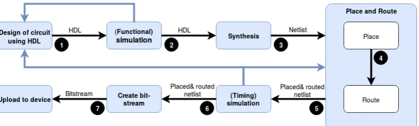
An overview of the FPGA design flow has been created in Figure2.1. The steps are elaborated here. The designer starts with designing a circuit in the preferred HDL (Step 1). All the required functionality is implemented in this design. This code is the starting point of the design flow. Like with any other type of pro-gramming the code is validated to see if it actually performs what the designer intended, this is performed in the second step. If the performance is satisfactory, the code can be synthesised (e.g. converting the code to a netlist of LUTs and FFs) in Step 3. Step 4 and 5 are often mentioned together [4] but are in fact separate which can be exploited for use of PR or other more advanced techniques, such as manual floorplanning1. By extracting the design before placing or routing,
man-1"Floorplanning is the process of choosing the best grouping and connectivity of logic in a design, and
[image:8.595.88.512.608.736.2]of manually placing blocks of logic in an FPGA, where the goal is to increase density, routability, or perfor-mance." [18] The floorplanning can be (manually) optimised to decrease the critical path and allow
ual adjustments can be made which can help in implementing such systems. After this step is completed, another simulation is performed to test the timing of the system and to identify possible errors. When timing is not satisfactory, routing and placing could be adjusted or the initial design should be changed (see blue lines in Figure2.1). When everything is complete, the placed and routed netlist can be converted to a bitstream which can be uploaded to the FPGA board (Step 7).
It must be noted that planning and routing is completely separate from the original design and dependent on the device it will be uploaded on. The result of synthesis will remain the same however. Hence, the designer can influence the design both through the initial code or by intervening in the placement and/or routing procedure.
2.2
Partial reconfiguration on the FPGA platform
The goal of PR is to exchangemoduleson the FPGA platform during runtime. Do-ing so requires the routDo-ing of I/O signals to the correct location on the FPGA. To be able to perform this, a portion of the FPGA needs to keep executing the re-quired tasks (including the reconfiguration). This part of the FPGA is known as thestatic region. This region will also host static parts of the system, such as I/O ports as they can never be (physically) moved. Logically, the part that will host the reconfigurable modules is nameddynamic region. This region can host a variety of different modules which can be initialised whenever required. The applica-tion of this region is limited by the configurable logic blocks (CLB) available in the hardware. Designers should take this into consideration when creating their reconfigurable modules.
2.2.1
Partial reconfiguration methodologies
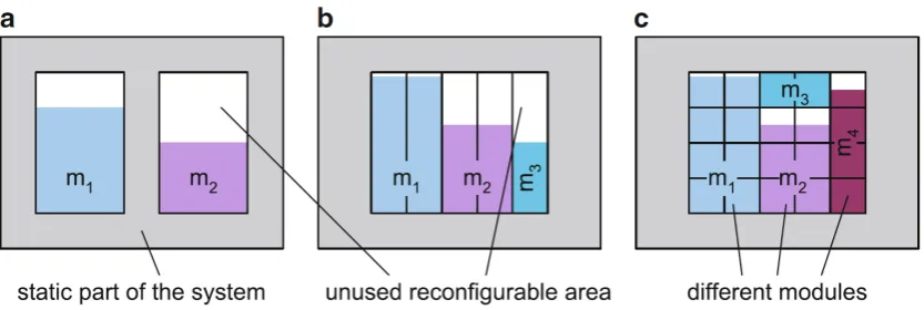
Currently there are a select number of choices for PR methodologies. The sim-plest and most widely supported form is theisland stylereconfiguration. The PR region is surrounded by the static region (hence the name; island) and the area can exclusively host one PR module at a time. The advantage of this type of con-figuration is that the interfaces to the module can be standardised, simplifying the communication from the static to the dynamic area. There are however, a num-ber of disadvantages that can be decreased by utilising a different methodology. For instance, the island should be large enough to host the largest PR module. In which case the utilisation of the available area is optimal. When a smaller module is inserted however, a large portion of area may go unused which is known as in-ternal fragmentation. The fact that solely one module can be hosted in an island means that this unused area cannot be utilised otherwise.
To overcome these limitations, the slot and grid style reconfiguration method-ologies were conceived [10]. The first divides the dynamic area into vertical slots of a fixed size, the latter divides the area in both horizontal and vertical direc-tion, e.g. a 2-D grid of relocatable chunks (see Figure2.2). With these styles, PR modules can use several slots/chunks to create the required area to host a PR
Figure 2.2: Three different PR methodologies: a) Island style, b) slot based and c) chunk based. Taken from [10].
module. If a module does not fully utilise a slot or chunk, some area goes unused, but this amount is significantly reduced when compared to the area of a larger island. Supporting these reconfiguration styles does require more effort however. Instead of communicating with a single island, several slots/chunks need to be interfaced. Next to the fact that slots/chunks need to communicate internally to perform the required task. Enabling all of this communication requires overhead which decreases the efficiency of the implementation [10].
It was stated before that slots or chunks have a fixed size. For communica-tion with each seccommunica-tion, a fixed amount of overhead is required. Hence, it would make sense to make larger slots/chunks. But this would reintroduce the issue of internal fragmentation. Hence, a trade-off should be found between the size and communication overhead of the slots/chunks.
2.2.2
Link between static and dynamic region
The static region should, as the name suggests, remain the same. At the same time, however, several different dynamic modules could be loaded during run-time. These should all work correctly and be interfaced with the static region. To accomplish this, a standardised interface has to be created. This is not a new idea as seen in sub-figures a) and b) in Figure2.3. These methods utilise cells which force the router to make a connection to the edge of both the PR module and the static region. When inserted, the PR module can then interface with the static re-gion. In the case of Figure2.3the older bus macros2 or the newer proxy logic are used. The use of these cells means an additional overhead of two cells for each connection. Additionally the proxy logic cells used today are set to route-through which makes them behave like a wire. Except for the fact that they introduce a small delay. When dealing with larger streams of data this delay can become sig-nificant and is hence not desired. Figure2.3also proposes a new method where PR-links, or in other words wires, are used for the connection. Modern day routers are not able to create this type of PR-links, which is why a different solution must be sought for.
Figure 2.3: Three different methods of connecting the dynamic to the static system. Taken from [12].
2.2.3
Switching PR modules
When all prior steps have been successfully completed, PR modules must be loaded onto the FPGA board. The first module can be loaded with the static system in what is known as a full-configuration. However, the goal with PR modules is to ex-change them during runtime. This can be achieved in a number of ways. Using for example the Vivado IDE (see Section2.3) it is possible to load a partial bitstream solely containing the information for the partial module. As such the information in the RP site will be overwritten with the information of the new module. Load-ing this partial bitstream is done usLoad-ing aJTAG interface. Alternatively, the Zynq family (with boards such as the Zedboard; see section2.5) provides the ability to upload a bitstream using the onboard processing system. Using this, the bitstream can be loaded into the programmable logic at any time using aPCAP interface. By utilising the communication between the two parts, the module can be loaded at the appropriate timing. A final option is to utilise ICAP to reconfigure the fab-ric. This method is similar to PCAP, but now the FPGA fabric itself implements a different module. This allows the FPGA to independently host partial dynamic reconfigurable projects.
2.3
The Vivado IDE
2.3.1
Implementing a PR island
The first step in implementing is to individually synthesise all parts of the de-sign. This means both the static design as well as all PR modules individually. A checkpoint must be created for each synthesised project, such that they can be loaded into the design later on. Next, the static design synthesis checkpoint must be loaded together with either a PR module, or a blackbox indicating the location of the modules. This design can then be placed and routed, after which the mod-ule/blackbox can be removed to leave only the static design. A checkpoint must be created of this design because this can then be used to execute placement and routing for all the other PR modules, each time loading a different module into the static system. A bitstream can be made for each implementation independently, such that it can be uploaded to the FPGA board (see Section2.2.3).
It must be noted that all of these steps can be combined and executed using a TCL file. This automates many of the steps but relies on the Vivado tools to properly execute all steps. In some instances it can be good to manually execute certain steps, such as allocating pblocks, to improve the overall design.
2.4
Rapidsmith2
Whereas Vivado tries to automate and abstract many processes, RapidSmith2 (RS2) [13] provides a lot of low level control (it is possible to interact with individual BELs3 for example). As such, it is possible to change both the floorplan and the routing on a larger scale, as well as fine-tune small elements. Installing and using RS2 is simplified through the use of the techreport [15]. This document also ex-plains how to use many of the components/functions. A small summary of the relevant information is given here for use in the report.
2.4.1
Storage types
To store the design created in Vivado, RS2 uses a number of variables. In order to properly use RS2, a good understanding of the different variables is required:
• Device: An overview of the platform; e.g. what sites are placed where in the fabric.
• Design: Provides an overview of the design created by the user; e.g. what cell types (from the cell library) are placed where in the fabricandhow these cells are routed.
• Cellnet: An overview of the connections between netlists.
• RouteTree: A structure to store routes in, more details are given in Section
2.4.3.
• Cell Library: A library with all available cell types to be implemented in the design.
• Tile: Equal to Vivado tiles; contains a number of sites.
• Site: Equal to Vivado sites; contains a number of cells.
• Cell: Similar to Vivado cells, the available types are found in the cell library.
• Wire: A structure for describing a connection. More details are given in Section2.4.2.
• RS2 provides more datastructures (e.g. BELs, PIPs, etc.), but these will not be discussed in detail as they are not relevant for the routing. These structures are mainly used for implementing low-level changes to the design.
2.4.2
Manipulation commands
Using RS2 it is possible to list all elements in the design, e.g. tiles, sites, cells, BELs, wires and PIPs. A list of all items can easily be invoked by issuing: getTiles(),
getSites(), etc. Alternatively, specific elements can be searched for by for ex-ample issuinggetBEL('PAD'). This will return all PADelements on the specific tile/site.
Wires
RS2 implements a special structure for documenting wires. In essence, there are two wire types: Programmable Interconnect Point (PIP) connections and Non-PIP connections. Here Non-PIP connections are simply a wire connecting to another wire, thus forming a simple connection. The PIP connections are locations where two wires are connected using a PIP which can be programmed. The PIP connec-tions can connect to a number of specific objects; site pins, BEL pins or a (BEL) route-through connection. The most important parts of a wire connection are the source and sink(s), these are labeled, whereas the Non-PIP connections are not [15]. The power supply and ground nets are handled separately, but do not have to be changed manually for changing the routing, so will not be discussed into more depth here.
To determine how routing is performed, more insight into the wire structure is required. RS2 identifies three major commands for retrieving information about wires [15]:
• "mywire.getWireConnections(): Returns a collection of all Connection ob-jects whose source is “mywire”. This collection can be iterated over to find all places a specific wire goes (i.e. what wires it connects to).
• conn.isPip(): Returns true if the wire connection “conn” is a PIP connec-tion. Returns false otherwise.
• conn.getSinkWire(): Returns the sink wire of a wire connection."
The RS2 techreport goes into more detail and gives code examples for using the specific commands and identifying the different types of wire (connections).
2.4.3
Route trees
these object for the user. To effectively change the routing, the structure of the route tree must be properly understood.
ARouteTreeis astructfor each wire that contains about the connection it is part of. It links the source of the connection and also lists all the sinks. Moreover the structcontains the route from the source element to the currentRouteTreeelement [15]:
• Wire: the actual wire theRouteTreeis describing. This can be any of the wires described before.
• Source: The name of the source of this connection. Here source is of the previously described type.
• Connection: shows the path from the source to the currentwire.
• Sinks: Shows thesinksthat are part of theconnection.
• Cost: A field for entering the cost of awire. This can be useful for routing algorithms.
2.4.4
Implementing routing
RS2 converts the routing of Vivado in a three-part routing structure. The first part is the lower level routing within a site. The second part, intersite routing, connects different sites together. Once a connection has been made between sites, the third part of the routing connects the intersite routing pin to elements within the site.
If there are routes leaving the specified tiles, this must be the intersite routes. Since a connection is required between the two sites, a route must be constructed between them. It is possible to adjust the routing however, fit within the specified tiles of the module. Since this route is part of the route tree (See Section2.4.3) the elements currently part of the tree must be removed. Subsequently, a new path must be created and the corresponding elements must be added to the routetree to once again complete the structure.
If the new route does not conflict with any of the existing routing, the design is still able to perform the original task as the sites are still connected. However, this new implementation does not contain nets that move outside the specified bounds.
Routing algorithms
In the example section RS2 provides two samples of routing algorithm. The first is very simple and named handrouter. This algorithm analyses the connections available to therouteTree. These options are printed and it is up to the user to select the best route. As the name suggests, a manual solution.
Figure 2.4: An overview of the Zedboard and it’s interfaces from the Vivado soft-ware [9].
2.5
The Zedboard
To actually test the implementation on hardware, a platform to work on is re-quired. Within the Zynq family, the Zedboard, an educational board, is avail-able. Besides the Artix-7 FPGA with 53,200 LUT’s and 106,400 FF’s, this board is equipped with a dual ARMR
CortexT M-A9 MPCoreT M which can operate up to
866MHz. Moreover, it has multiple I/O options, such as: slide switches, push but-tons, LEDs and a 128x32 OLED screen [20]. These interfaces and more are shown in Figure2.4.
Chapter 3
Analysing the Vivado routing
A number of elements of the created example design have to be analysed; the proxy logic used to connect the static and dynamic parts, the routing of the partial reconfigurable module and if the nets in the module leave the specified area. Once incorrect routes are detected they must be corrected, which is discussed in Section
3.3.
3.1
Proxy logic
In the 2017 version of Vivado, Xilinx presented the partition pins [19]. These pins satisfy the desire as posed in Figure 2.3 as it does not require additional physi-cal cells which require resources and could influence timing performance. Since the interfaces between the static design and the reconfigurable modules are now handled by Vivado, it is not required to implement these using RS2. Whatcan be analysed is the routing to-and-from these pins. If this is different for different modules it can have an influence on the performance between modules.
Before partition pins were implemented, an additional step had to be per-formed using RS2 to insert connection points between the static and dynamic re-gion to avoid the use of proxy logic. In the list described in Chapter4, this would have been inserted after Step 2. There the project would be exported to RS2, the desired interfaces would be inserted, after which the design would be reinserted into Vivado.
3.2
Routing analysis
The second item to be investigated is if routes go outside the boundaries set for the (PR) module. This is not meant to happen as it might have influences on the (routing of the) static system. Detecting the crossing of these boundaries is imple-mented using functions which are elucidated in Sections3.2.1and3.2.2.
3.2.1
Specifying bounds
3.2.2
Detecting incorrect routes
Once the allowed tiles are specified and the nets originating from these tiles are found, it is possible to find all individual route trees and determine if the routes they describe are actually going outside the determined tiles. This is done in List-ing3.1. The detection of routes that leave the specified P-block is handled using the recursive functioniteratingOverRouteTreewhich is called by a helper func-tion sinksOutsideArea. The recursive function performs all the work and calls upon itself to traverse along the net. The function has methods for determining the different types of connections (e.g. leaf cells which connect to a site or BEL pin, or a simple wire connection) and is based on the design analyser example from RS2. The goal of this algorithm is to find routes that originate from the P-block and return to the P-block again. Other routes that leave the P-block might connect to the static region or I/O-pins and should not be removed.
The iteratingOverRouteTree function marks any route leaving the P-block from a site pin as a possible incorrect route. If this route then leaves the specified tiles, a flag is raised. This flag is recursively passed down, until the route reaches a leaf cell again. At this point it is evaluated on which tile the connected pin is located. If this is a tile part of the P-block, the net is added to the list of incorrectly routed nets. If this is not the case, the route is continued until the end.
It was chosen to iterate over the routetrees to find all relevant information. This way, all information is based on the current implementation. Another possibility would have been to utilise thetargetTilevariable which is used in the A* algo-rithm. This way, as soon as a route leaves the specified tiles, this variable can be evaluated to find if a route is correct or not. This does assume that this variable is always correctly set, which is not guaranteed by RS2.
1 public staticCollection<SitePin> sinksOutsideArea(Collection<Tile> selectedTiles, CellNet selectedNet) {
2 Collection<SitePin> sinksToRoute =newArrayList<>();//Start a list to add sinkPins to
3 if(selectedNet.isSourced() && !selectedNet.isGNDNet() && !selectedNet.isVCCNet() && !selectedNet.isClkNet()) {
4 sinksToRoute.addAll(iteratingOverRouteTree(selectedNet, selectedNet.getSourceRouteTree(),true, 0, selectedTiles)); 5 }
6 returnsinksToRoute; 7 }
8
9 public staticCollection<SitePin> iteratingOverRouteTree(CellNet n, RouteTree rt,boolean
inside,intpossible, Collection<Tile> selectedTiles) {
10 Collection<SitePin> wrongPins =newArrayList<>(); 11 if(rt ==null)returnwrongPins;
12
13 Collection<RouteTree> sinkTrees = rt.getSinkTrees(); 14 if(rt.isLeaf()) {
15 SitePin sp = rt.getConnectedSitePin(); 16 if(sp !=null) {
17 if(inside) {
18 // Inside site, so look for correct intersite route tree to leave on
19 for(RouteTree rt1 : n.getIntersiteRouteTreeList()) { 20 if(sp.getExternalWire().equals(rt1.getWire())) { 21 possible = 1;
23 returnwrongPins;
24 }
25 }
26 returnwrongPins;
27 }
28 else
29 // Outside site, so just follow the route from the general
routing fabric and into a site
30 if(possible == 2 &&
selectedTiles.contains(sp.getInternalWire().getTile())) { 31 for(SitePin sitePin : n.getSitePins()) {//Add all the
input sitePins from the net
32 if(sitePin.isInput())
33 wrongPins.add(sitePin);
34 }
35 returnwrongPins;
36 }
37 possible = 0;
38 wrongPins.addAll(iteratingOverRouteTree(n,
n.getSinkRouteTree(sp), inside, possible, selectedTiles)); 39 returnwrongPins;
40 }
41 }// End of rt.isLeaf()
42
43 else{
44 // Otherwise, if it is not a leaf route tree, then iterate across its sink trees
45 for(Iterator<RouteTree> it = sinkTrees.iterator(); it.hasNext(); ) { 46 RouteTree sink = it.next();
47
48 if(!selectedTiles.contains(sink.getWire().getTile())) {//If it is in the wrong tile add it to the list
49 possible = 2;
50 wrongPins.addAll(iteratingOverRouteTree(n, sink, inside, possible, selectedTiles));
51 returnwrongPins;
52 }
53 wrongPins.addAll(iteratingOverRouteTree(n, sink, inside, possible, selectedTiles));
54 }
55 }
56 returnwrongPins; 57 }
Listing 3.1: The code for identifying which nets leave the area specified by the function from the previous Section3.2.1.
In the helper function (sinksOutsideArea), another check is being performed to avoid analysing nets that are either for the clock, VCC or GND since these do not follow the standard routing method and do not have to be adjusted.
Figure 3.1: The routes in the AES design after being removed by the routes-out-of-bounds function. It can be noted that the top I/O-bank is now disconnected.
Removing selective routes
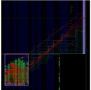
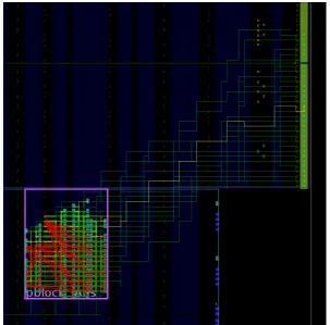
The first iteration of this function removed almost all routes leaving the P-block, since it performs a simple check if the intersite-route ever leaves the specified tiles. The result of which can be found in Figure3.1. Since communication between static and dynamic region is required, these routes should not be removed. It can be seen how the routes to the top I/O-bank are disconnected, which is unde-sirable. To solve this problem, the algorithm described previously was properly implemented. Now only routes leavingandreturning to the P-block are marked as incorrect. This yields the results found in Figure3.2.
With the updated code, a collection is filled with pins attached to the found incorrect nets. Based on thedesignAnalyser, the recursive function iterates over all elements. For the original purpose this example function prints every element in the net. Instead, this application performs an analysis on each element to see if it is not on one of the allowed tiles, the corresponding input pins of the net are added to the collection. From Figure3.2it can be seen that all the out-of-bounds routes are found and removed, whereas the other routes (such as those to the static region) remain.
3.3
Alternative routing
Figure 3.2: The routes in the AES design after being removed by the routes-out-of-bounds function. With the altered algorithm, only routes returning to the P-block are removed. The routes at the bottom of the P-block are routed to a site elsewhere.
going out-of-bounds, the routing algorithm was slightly adjusted to incorporate the current tile the wire is in such that it will not again create an incorrect route outside of the bounds. The new implementation of the A*routeNet function is shown in ListingA.3. The function receives the appropriate tile and net collections created using Listings3.1and3.1to determine whichSitePinsmust be re-routed. To get it working properly, the priority queue –which is used to select the most cost efficient route– must be initialised. This way, aisEmpty()call can be made to determine if a new queue must be made using theresortPriorityQueuefunction from the original RS2 algorithm.
3.4
Wrapper
To call all previously described functions in the correct succession, a class named
routeOutOfBounds_Exampleis used. It is given in Listing3.2. This function first determines the correct tiles and nets using the functions from Listings A.1 and
1 public static voidmain(String[] args)throwsIOException {
2 doublestartTime = System.nanoTime();//This is the time at which the analysis is started
3 // load the device and design
4 String checkpoint ="/home/matthijs/AES3.3.rscp"; 5 System.out.println("Loading Device and Design...");
6 VivadoCheckpoint vcp = VivadoInterface.loadRSCP(checkpoint); 7 CellDesign design = vcp.getDesign();
8 Device device = vcp.getDevice(); 9 CellLibrary libCells = vcp.getLibCells(); 10
11 // loading reverse wire connections
12 device.loadExtendedInfo(); 13
14 //Creating variables which can hold both the routetree and the statistics
15 Results results =newResults(); 16 intreroutedRoutes = 0;
17 intcorrectRoutes = 0; 18 intwrongRoutes = 0; 19 interrorRoutes = 0; 20
21 // Routing net
22 System.out.println("Re−routing Nets...");
23 RouteOutOfBounds router =newRouteOutOfBounds(); 24
25 //Find the selected Tiles and nets originating from those Tiles
26 Collection<Tile> areaTiles = RouteOutOfBounds.selectingArea(device, device.getTile("CLBLM_L_X36Y28"), device.getTile("CLBLM_R_X43Y49"));
//Collection of allowed Tiles
27 Collection<CellNet> areaNets = RouteOutOfBounds.selectingNets(areaTiles, design);
//Collection of allowed nets (those leaving from the allowed Tiles)
28
29 for(CellNet net : areaNets) {
30 System.out.println("\tCurrently working on net: "+ net.toString()); 31
32 // Find the pins that need to be routed for the net
33 Iterator<SitePin> sinksToRoute =
RouteOutOfBounds.sinksOutsideArea(areaTiles, net).iterator();//Iterator for the sinks that must be re−routed
34
35 if(sinksToRoute.hasNext()) { 36 net.unrouteIntersite();
37 results = router.routeNet(areaTiles, areaNets, sinksToRoute, net);
38 }
39
40 if(results.routeTree !=null) { 41 net.unrouteIntersite();
42 net.addIntersiteRouteTree(results.routeTree);
43 }
44
45 //Update the statistical values
46 reroutedRoutes += results.reroutedRoutes; 47 correctRoutes += results.correctRoutes;
48 wrongRoutes += results.wrongRoutes; 49 errorRoutes += results.errorRoutes; 50 }
51
53 System.out.println("Done!");
54 doubleestimatedTime = (System.nanoTime()−startTime)/1000000000; 55 System.out.println("This took "+ estimatedTime +" seconds");
56
57 System.out.println(reroutedRoutes +" pins were rerouted of which "+ correctRoutes +
" were correct, "+ wrongRoutes +" could not be rerouted and "+ errorRoutes +" caused an error.");
58 floatpercentage = (correctRoutes∗100f)/reroutedRoutes; 59 System.out.println("Therefore, "+ percentage +"% is correct."); 60
61 // Re−evaluate if routes are correct by applying the sinksOutsideArea function again
62 intcounter = 0;
63 for(CellNet net : areaNets) {//Iterate over all nets again and see if wires leave area
64 if(!net.isClkNet() && !net.isGNDNet() && !net.isVCCNet()) { 65 for(Iterator<SitePin> sinksToRoute =
RouteOutOfBounds.sinksOutsideArea(areaTiles, net).iterator(); sinksToRoute.hasNext();){
66 SitePin sink = sinksToRoute.next(); 67 if(sink !=null)
68 counter++;
69 }
70 }
71 }
72 System.out.println("\nThe routes−out−of−bounds function found that "+ counter +" routes are still incorrect.");
73
74 // Evaluate all nets
75 intnumrouted= 0;
76 for(CellNet n: design.getNets())
77 if(n.getIntersiteRouteTreeList()!=null) 78 numrouted++;
79 System.out.println("The design has: "+ design.getNets().size() +" nets, "+ numrouted +
" of them are routed."); 80
81 //Export the altered design
82 System.out.println("\nExporting now...");
83 VivadoInterface.writeTCP("/home/matthijs/Documents/temp.tcp", design, device, libCells);
84 System.out.println("Done!");
Chapter 4
Example applications
The general goal is to adapt the routing of the FPGA to make it more coherent. Doing this requires a number of steps which are listed below. This list does assume that a PR design is ready and synthesised and only goes through the steps that follow after synthesis.
1. Load the static design into Vivado.
2. Allocate black box(es) for the PR module(s).
3. Perform the usual design flow steps; place and route (e.g. 4 & 5 from Figure
2.1).
4. Perform the same steps for all PR modules in order to get checkpoints for all of them. As described in Section2.4.
5. Applypr_verifyin order to validate all PR implementations.
6. Export to RS2 to evaluate the routing of the module and possibly adjust it.
7. Convert the project back to Vivado and create the final bitstream (step 7 from Figure2.1).
Analysing and testing the implementation of adjusted routing requires an ex-ample program on which this analysis can be applied. This will need to be a PR-system so, this requires a static PR-system able to host a PR module. Two projects were utilised. On the one hand an AES core [6] and on the other a project that can create random numbers using one module and test for primality with another. The latter will be created to work with larger (32 bit) prime numbers, which will require a significant amount of logic. Both the module for prime verification as well as the random number generator module will utilise the same interface structure. The exact code implementation for the prime verification can be found in Appendix
B.
4.1
AES core
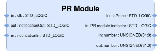
Figure 4.1: The interfaces of the partial reconfigurable modules.
4.2
Prime verification
To allow for the switching between PR modules, a standardised interface is re-quired. In this way, each module connects to the same interfaces and the routing of the static system can be simplified. For the created system (see AppendixBfor the source code), a number of interfaces are defined for the PR modules as defined in Figure4.1.
The difference between the two modules is that one should send and the other receive the 32-bit random number. VHDL offers ’inout’ interfaces. These are however, not supported by the FPGA fabric as this does not support bidirectional communication. Hence, Vivado needs to implement a route for either direction which is not efficient in terms of gates and is error prone. Instead, it was chosen to implement two interfaces for ’in’ and ’out’ respectively. The isPrimeinterface indicates if the the number is in fact prime, or not. ThePR module indicatoris a sim-ple boolean that indicates to the static system which module is currently loaded. This makes sure that the static system will only communicate with the module if the correct one is loaded. The other interfaces are for correct communication between the static and dynamic region in order to properly time all events.
4.2.1
Final implementation
When applying the code from AppendixBas a PR project, the code can be fully synthesised and implemented. The total resource costs for this project are pre-sented in Table4.1. Since this is a simple example program, the resources take up a fraction of the Zedboard’s available gates (see Section 2.5), but more than the AES core. The P-Block has been arbitrarily placed in the fabric, but does (as Vivado requires) span the height of an entire clock region.
An attempt was made to implement this project as a static design. Unfortu-nately, Vivado simplifies the design to 2 LUTs and 5 FFs, which is not suitable for this application.
Table 4.1: An overview of the resource requirements of the individual parts of the example design.
LUT FF
Static design 833 376
Chapter 5
Evaluation
5.1
Prime verification project
Creating the example project provided a proper tutorial to understanding both the Vivado tooling, as well as partial reconfiguration. Using this it was easier to understand how PR worked and what difficulties would arise from working on projects with PR modules.
During the implementation of the example project, a few problems occurred, many of which were solvable. Except for the prime verification module. The ap-plied method (which is inefficient, but this ensures larger amounts of logic) for de-termining primality requires the FPGA to divide the random number by all num-ber up to the square root of the numnum-ber itself. For a 32-bit numnum-ber this requires at most√232 = 65536divisions. With this number of iterations on a for-loop, the
design did not synthesise correctly. After trial and error, it was determined that using a 27-bit number is still eligible for prime verification with √227 ≈ 11586
iterations of the for-loop. This was implemented and the random number was adjusted in the final code too by discarding the top bits.
5.2
Routing analysis
The algorithms posed in Chapter3were applied to the AES core project. Initially this yielded no results as Vivado was able to format all routes within the partial reconfigurable module. An attempt was made to resize the P-block allocated for the module to force routes to go outside. Unfortunately, the block has a minimum size depending on the amount of logic it must fit. If the size is decreased fur-ther. With this limitation it was not possible to create routes that move out of the bounds.
To circumvent this problem, a different VHDL project was sourced. This AES core contained a little less logic, but could also not be forced to route outside the P-block. After more tinkering it was observed that a static implementation restricted to a specified area does create routes leaving that area, similar to the desired sit-uation where routes leave the partial reconfigurable module1. This could be the starting point for the re-routing algorithm. For the prime verification project a static implementation proved troublesome as Vivado simplifies the design to 2 LUTs and 5 FFs which is not enough logic to perform any kind of analysis on.
Moving forward, the AES core is used for verification. With this project it was possible to apply the algorithm described in Chapter3. Using the class from List-ing3.2the design is imported and the appropriate functions are called. This piece of code requires the user to manually specify the corner tiles of the PR area and
1This also circumvents the need for the expensive Vivado partial reconfiguration license, as it
Table 5.1: An overview of the result obtained on the AES core project.
AES core
Correct routes 12490
Incorrect routes 241
Erroneous routes 0
Total routes 12731
Percentage correct 98.11% Execute time 8.88 seconds
the file location of the RSCP checkpoint. These can differ depending on the use-case and between projects. With the correct names set, the AES core project was imported into RS2 and the code was run. The results are summarised in Table5.1.
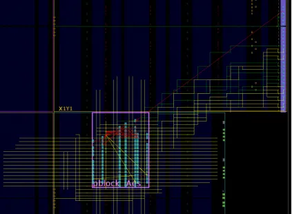
From the results in Table 5.1 it can be observed that there is a small number of routes that could not be rerouted. Since the available fabric is limited within the P-block, it can occur that some routes cannot be routed within the boundaries. Hence, they are not unrouted and the design will keep some imperfections. It can be seen that these routes make up 1.89% of the total routes. Figure5.1illustrates how there are still some nets fanning out from the P-block. There are still some red nets which correspond to the incorrect routes from Table5.1.
[image:26.595.87.511.420.730.2]Chapter 6
Discussion
This thesis required a thorough understanding of many different aspects regard-ing the FPGA. Aspects that are not part of the Electrical Engineerregard-ing curriculum. Naturally, learning and understanding new material is integral part of a Bache-lor Assignment. However, learning how to operate the software programs Vivado and RapidSmith2 required a significant portion of time which limited the progress that could be made on actual research.
In order to adapt routing on a very low level, RapidSmith2 was used. Since this program is currently still under heavy development, there are still some bugs. Some of which are solved by software updates, because RS2 is updated regularly. Unfortunately, some issues still remained, and getting RS2 compatible with the available Zedboard proved to be very troublesome.
A significant portion of time was spent on fixing the numerous problems that arose during installation of the Zedboard with RS2. After numerous attempts of creating the required configuration files, the program was downgraded to ver-sion 1.1.1. This verver-sion did not allow for the creation of the configuration files, but was able to recognise the Zedboard. All of this thanks to the help of Gerhard Mlady, who helped with solving many of the issues with RS2. Moreover, he was able to provide the required configuration files which I was not able to create my-self through RS2. After numerous tests, it turns out that the Zedboard is still not fully supported by RS2 yet. Many of the sites are improperly named during file creation which results in error prompts when the file is imported. Solving this would require going through hundreds of pin names and replacing them with a name that is supported by RS2.
It is likely that problems such as these are solved in the future. For this re-search however, this meant the Zedboard could not be utilised for the creation of the Vivado project. This also eliminated the testing option of uploading the ad-justed project to the Zedboard to verify if the operation is the same as before.
The choice for using the Zedboard was made as it was physically available. This allowed for the option to test the example project when initially making it, as well as after the re-routing process. The latter would be a feasible method to verify if the functionality indeed remains the same. Since it was not possible to use the Zedboard in RS2, an alternative was found in an Artix7 (xc7a100t-csg324) FPGA. This board was not available, but is supported by default in RS2. Therefore it is at least possible to apply the discussed algorithms and verify if they operate correctly. Using the Artix7 FPGA made the usage of RS2 trivial, but all testing has to be in the digital domain and cannot be produced on an actual FPGA board. Seeing that Gerhard Mlady is able to use the RS2 tooling together with the Zed-board which would suggest that it is possible to use it, when given more time.
oc-curred in the example code supplied by RS2. For example, the resizing of the
PriorityQueuedid not properly work. This meant that only a handful of routes could be rerouted before running into exception which voided the rest of the routes. Moreover, a problem occurred when trying to read the wire and connec-tion of eachRouteTreeas some had no wires connected, so returnednull. With this value, retrieving a connection type threw another exception.
Chapter 7
Conclusion
This research has proven that it is feasible to utilise RS2 to analyse and adjust the routing. It was possible to apply the developed algorithm to the AES project for verification. The prime verification module was created to host enough logic to test applications created using RS2, which can be found to be true when compar-ing the resources of the two designs. It was found that routes only leave the allo-cated area if the design is implemented statically, whereas the routes remain inside a partial reconfigurable module. It was not possible to implement the prime veri-fication project as a static design, so the AES core was used for all veriveri-fication pro-cesses. Despite not being used for verification, the prime verification project has proven that the default Vivado routing for partial reconfigurable modules routes within the module itself, which is what is desired for these modules. The fact that routes remain within the partial reconfigurable modules proves hopeful for fur-ther development of PR projects including more advanced reconfiguration styles such as the slot based design.
The routing analysis is performed accurately, all incorrect routes (those that leave the partial reconfigurable module and do not route to outside the module) are found and can effectively be removed as is shown in Figure3.2. Subsequently, an A* algorithm is employed to reroute the nets that have been unrouted. Due to the limited amount of logic within the specified area it is sometimes not possible for the simple A* algorithm to find a route that adheres to the requirements. As an effect, 1.89% of the routes cannot be properly re-routed. By reducing the num-ber of incorrect routes the disadvantageous effects of the PR modules on the static fabric can be significantly reduced.
Chapter 8
Recommendations
In this work, the first steps towards alternative routing in RS2 are made. It must be noted that the methods here are not the most efficient or fastest methods and can most certainly be improved. A small portion of 1.89% of the routes cannot be properly rerouted. This number should be improved and most preferably be re-duced to 0% to provide the desired outcome. The example A* algorithm, created by RS2 is known not to be the most efficient algorithm [8]. When improving the routing it is thus advised to implement a different algorithm with better perfor-mance that is also able to fit all routes within the required area.
Additionally, the currently implemented method requires more testing, prefer-ably on an actual hardware device as was attempted with the Zedboard. This would verify if the routing procedure is actually effective and can directly show if the re-routed nets still deliver the same performance. When the design is im-ported into Vivado, it is also possible to perform a timing analysis and contrast it to the original design. This way, the effect of the re-routing can be evaluated. It would make sense that timing performance is affected since fitting routes within the partial reconfigurable module does not deliver the most time effective routes.
With the detection of out-of-bounds routes, the analysis of routing around PR modules is not complete. When analysing the routing within PR modules, it is also important to verify if each module uses the same routing towards the parti-tion pins (or the older proxy logic cells). If these routes differ depending on the module, this could lead to differences in the performance. Also, it would be in-teresting to study the effect of shrinking the size of the modules and which effects this has on both the routes inside the module moving out-of-bounds, as well as the effect on these routes to the partition pins.
Bibliography
[1] J. Angermeier, D. Ziener, M. Glaß, and J. Teich. Stress-aware module place-ment on reconfigurable devices. In2011 21st International Conference on Field Programmable Logic and Applications, pages 277–281, Sept 2011.
[2] Christian Beckhoff, Dirk Koch, and Jim Torresen. Go Ahead: A Partial Re-configuration Framework. InField-Programmable Custom Computing Machines (FCCM), 2012 IEEE 20th Annual International Symposium on, pages 37–44, 5 2012.
[3] Mark Bourgeault. Altera’s partial reconfiguration flow.Technical Report, 2011.
[4] Shih-Chun Chen and Yao-Wen Chang. Fpga placement and routing. In Computer-Aided Design (ICCAD), 2017 IEEE/ACM International Conference, pages 914–921, 13–16 November 2017.
[5] Nij Dorairaj, Eric Shiflet, and Mark Goosman. PlanAhead Software as a Plat-form for Partial Reconfiguration. Xilinx XCELL Journal, Art, 55:68–71, 2005.
[6] Jerzy Gbur. Aes_128_192_256. Wroclaw University of Science and Technology, May 2006.
[7] Travis Haroldsen, Brent Nelson, and Brad Hutchings. Rapidsmith 2: A framework for bel-level cad exploration on xilinx fpgas. InProceedings of the 2015 ACM/SIGDA International Symposium on Field-Programmable Gate Arrays, FPGA ’15, pages 66–69, New York, NY, USA, 2015. ACM.
[8] P. E. Hart, N. J. Nilsson, and B. Raphael. A formal basis for the heuristic determination of minimum cost paths. IEEE Transactions on Systems Science and Cybernetics, 4(2):100–107, July 1968.
[9] Xilinx Inc. VivadoR
design suite, 2017.2.
[10] Dirk Koch. Partial Reconfiguration on FPGAs: Architectures, Tools and Applica-tions, volume 153. Springer, 2012.
[11] Dirk Koch, Christian Beckhoff, and Jürgen Teich. ReCoBus-Builder - a Novel Tool and Technique to Build Statically and Dynamically Reconfig-urable Systems for FPGAs. InProceedings of International Conference on Field-Programmable Logic and Applications (FPL 08), pages 119–124, Heidelberg, Ger-many, September 2008.
[12] Dirk Koch, Jim Torresen, Christian Beckhoff, Daniel Ziener, Christopher Dennl, Volker Breuer, Jürgen Teich, Michael Feilen, and Walter Stechele. Par-tial reconfiguration on fpgas in practice – tools and applications. In Proceed-ings of the 2012 Architecture of Computing Systems (ARCS’12), pages 297–319, February 2012.
[14] Michael Mattioli. Driving the oled display on the zedboard. https://
github.com/mmattioli/ZedBoard-OLED, May 2017.
[15] Brent Nelson, Thomas Townsend, and Travis Haroldsen. RAPIDSMITH2 A Library for Lowlevel Manipulation of Vivado Designs at the Cell/BEL Level -Technical Report and Documentation. February 2018.
[16] Stan Ng. Binary to bcd. https://www.quora.com/
How-do-I-convert-an-8-bit-binary-number-to-BCD-in-VHDL/answer/
Stan-Ng-2, June 2017.
[17] Stephen M. Trimberger, Richard A. Carberry, Robert Anders Johnson, and Jennifer Wong. Method of time multiplexing a programmable logic device, Nov 2002. US 5646545A.
[18] Xilinx. Floorplanning Methodology Guide, page 9. Springer, May 2010.
[19] Xilinx. Vivado Design Suite User Guide Partial Reconfiguration (UG909). April 2017.
[20] Xilinx. Zynq-7000 all programmable soc data sheet: Overview.
https://www.xilinx.com/support/documentation/data_sheets/
Appendix A
Re-routing algorithm code
In Section3.2, a description has been given of a number of functions. The code to realise the described behaviour is presented here.
Specifying tiles
1 public staticCollection<Tile> selectingArea(Device device, Tile bottomLeft, Tile topRight) {// This function finds all the nets leaving the specified (PR) area
2 Collection<Tile> allTiles = device.getTiles();
3 Collection<Tile> selectedTiles =newArrayList<>(); 4
5 int[] coordinateBottomLeft =
{bottomLeft.getTileXCoordinate(),bottomLeft.getTileYCoordinate()}; 6 int[] coordinateTopRight =
{topRight.getTileXCoordinate(),topRight.getTileYCoordinate()}; 7
8 for(Tile tile : allTiles) {//Populate selectedTiles with all tiles within the boundaries
9 int[] tempCoordinate = {tile.getTileXCoordinate(), tile.getTileYCoordinate()}; 10 if(tempCoordinate[0] <= coordinateTopRight[0] && //See if X−coordinate is
smaller that the topRight coordinate
11 tempCoordinate[0] >= coordinateBottomLeft[0] &&//See if X−coordinate is larger that the bottomLeft coordinate
12 tempCoordinate[1] <= coordinateTopRight[1] && //See if Y−coordinate is smaller that the topRight coordinate
13 tempCoordinate[1] >= coordinateBottomLeft[1]) {//See if Y−coordinate is larger that the bottomLeft coordinate
14 selectedTiles.add(tile);
15 }
16 }
17 returnselectedTiles; 18 }
Listing A.1: The code for specifying the tiles which are part of the region based on a bottom left and top right coordinate.
Specifying nets
1 public staticCollection<CellNet> selectingNets(Collection<Tile> selectedTiles, CellDesign design) {
2 Collection<CellNet> selectedNets =newArrayList<>();//A list for nets originating from the selectedTiles
3 for(CellNet n : design.getNets()) {//Populate the selectedNets collection
4 if(n.isSourced() && !n.isGNDNet() && !n.isVCCNet() && !n.isClkNet()) { 5 for(SitePin p : n.getSourceSitePins()) {
6 if(selectedTiles.contains(p.getSite().getTile())) 7 selectedNets.add(n);
8 }
9 }
11 returnselectedNets; 12 }
Listing A.2: The code for specifying which nets originate from the collection of tiles derived in ListingA.1.
Adapted A* routing algorithm
1 publicResults routeNet(Collection<Tile> areaTiles, Collection<CellNet> areaNets, Iterator<SitePin> sinksToRoute, CellNet net) {
2 // Initialize the route
3 RouteTree start = initializeRoute(net);//The routetree to be returned
4 Set<RouteTree> terminals =newHashSet<>(); 5
6 //Initialize return object
7 Results results =newResults();
8 results.routeTree =newRouteTree(null); 9 results.reroutedRoutes = 0;
10 results.correctRoutes = 0; 11 results.wrongRoutes = 0; 12 results.errorRoutes = 0; 13
14 assert sinksToRoute.hasNext() :"There are no CellNet objects to be re−routed for this net. This means the detection of incorrect routes went wrong!";
15
16 // Iterate over each sink SitePin in the net, and find a valid route to it.
17 SKIP_SINK :
18 while(sinksToRoute.hasNext()) {
19 // initialize the target wire, and priority queue
20 SitePin sink = sinksToRoute.next();
21 Wire targetWire = getTargetSinkWire(sink); 22 targetTile = targetWire.getTile();
23 resortPriorityQueue(start); 24
25 // Notify user which pin we are working on
26 System.out.println("\t\tActually re−routing sink: "+ sink); 27
28 // Update the number of routes being worked on for the statistics
29 results.reroutedRoutes++; 30
31 // Variables for while−loop
32 booleanrouteFound =false; 33 intcount = 0;
34
35 while(!routeFound) {//This loop actually builds the routing data structure
36 count++;
37 if(count > 50000) {// max = 1000000
38 System.out.println("\t\t\tCould not find an alternative route, so skipping this!");
39 results.wrongRoutes++; 40 breakSKIP_SINK;
41 }
42 // Grab the lowest cost route from the queue
43 RouteTree current = priorityQueue.poll(); 44
46 Set<Wire> existingBranches =
usedConnectionMap.getOrDefault(current,newHashSet<Wire>()); 47
48 // Search all connections for the wire of the current RouteTree
49 try{// In case the wire does not have a connection, the exception is caught
50 for(Connection connection :
current.getWire().getWireConnections()) {
51 Wire sinkWire = connection.getSinkWire(); 52
53 // Solution has been found
54 if(sinkWire.equals(targetWire)) { 55 RouteTree sinkTree =
current.addConnection(connection); 56 sinkTree = finializeRoute(sinkTree); 57 terminals.add(sinkTree);
58 routeFound =true; 59 results.correctRoutes++;
60 break;
61 }
62 // Only create and add a new RouteTree object if it
doesn’t already exist in the queue
63 if(!existingBranches.contains(sinkWire) && areaTiles.contains(sinkWire.getTile())) { 64 RouteTree sinkTree =
current.addConnection(connection); 65 sinkTree.setCost(current.getCost() + 1); 66 priorityQueue.add(sinkTree);
67 existingBranches.add(sinkWire);
68 }
69 }
70 }
71 catch(NullPointerException ex) {
72 System.out.println("\t\t\tCould not find wire connected to this pin!");
73 results.errorRoutes++; 74 breakSKIP_SINK;
75 }
76 usedConnectionMap.put(current, existingBranches);
77 }
78 // prune RouteTree objects not used in the final solution. This is not very efficient...
79 start.prune(terminals); 80 results.routeTree = start; 81 }
82 returnresults; 83 }
Appendix B
VHDL code
As described in Chapter4, a sample VHDL code is required to work with. The source code of both the static system as well as the two PR modules are stated here. It must be noted that the prime verification algorithm is most certainly not the best or most efficient algorithm, but for the sake of this example it is more than sufficient.
For the creation of a random 32-bit number, a long (8000 bits)std_logic_vector with random bits is used. An index increases every clock cycle. Because of the ran-dom timing of requesting a number, the index will have a ’ranran-dom’ value. Using the index, a 32 bits can be retrieved from thestd_logic_vector. When the in-dex is within the last 32 bits of the first 32 bits of the std_logic_vectorwill be returned. The possibility that this happens is 2501 so reasonably small. The final implementation can be found in ListingB.2.
For the conversion of this 32-bit number to a format that can be printed on the OLED on the Zedboard (BCD), the solution by Stan Ng was used [16]. This is implemented as a function in the static design (ListingB.1).
To print the number on the Zedboard’s OLED screen; the Digitlent OLED li-brary modified for Zedboard by Michael Mattioli was used [14]. It must be noted that such an OLED screen is not available for the Artix7 board which was used as an alternative to the Zedboard.
1 libraryIEEE;
2 useIEEE.STD_LOGIC_1164.ALL; 3 useIEEE.NUMERIC_STD.ALL; 4
5 entityZedboardis
6 Port(
7 clk :inSTD_LOGIC; 8 reset :inSTD_LOGIC; 9 nextState :inSTD_LOGIC; 10 displayLed :outSTD_LOGIC; 11 primeLed :outSTD_LOGIC; 12 generateLed :outSTD_LOGIC; 13 LD7 :outstd_logic;
14 oled_sdin :outstd_logic; 15 oled_sclk :outstd_logic; 16 oled_dc :outstd_logic; 17 oled_res :outstd_logic; 18 oled_vbat :outstd_logic; 19 oled_vdd :outstd_logic 20 );
21 endZedboard; 22
23 architectureBehavioralofZedboardis
24
25 FUNCTIONnumber2bcd (in_binary:UNSIGNED(31DOWNTO0))RETURNstd_logic_vectorIS
26
28
29 variables_digit_0 : unsigned( 3downto0):="0000"; 30 variables_digit_1 : unsigned( 3downto0):="0000"; 31 variables_digit_2 : unsigned( 3downto0):="0000"; 32 variables_digit_3 : unsigned( 3downto0):="0000"; 33 variables_digit_4 : unsigned( 3downto0):="0000"; 34 variables_digit_5 : unsigned( 3downto0):="0000"; 35 variables_digit_6 : unsigned( 3downto0):="0000"; 36 variables_digit_7 : unsigned( 3downto0):="0000"; 37 variables_digit_8 : unsigned( 3downto0):="0000"; 38 variables_digit_9 : unsigned( 3downto0):="0000"; 39
40 BEGIN
41 foriin31downto0loop
42 if(s_digit_9 >= 5)thens_digit_9 := s_digit_9 + 3;end if; 43 if(s_digit_8 >= 5)thens_digit_8 := s_digit_8 + 3;end if; 44 if(s_digit_7 >= 5)thens_digit_7 := s_digit_7 + 3;end if; 45 if(s_digit_6 >= 5)thens_digit_6 := s_digit_6 + 3;end if; 46 if(s_digit_5 >= 5)thens_digit_5 := s_digit_5 + 3;end if; 47 if(s_digit_4 >= 5)thens_digit_4 := s_digit_4 + 3;end if; 48 if(s_digit_3 >= 5)thens_digit_3 := s_digit_3 + 3;end if; 49 if(s_digit_2 >= 5)thens_digit_2 := s_digit_2 + 3;end if; 50 if(s_digit_1 >= 5)thens_digit_1 := s_digit_1 + 3;end if; 51 if(s_digit_0 >= 5)thens_digit_0 := s_digit_0 + 3;end if; 52 s_digit_9 := s_digit_9sll1; s_digit_9(0) := s_digit_8(3); 53 s_digit_8 := s_digit_8sll1; s_digit_8(0) := s_digit_7(3); 54 s_digit_7 := s_digit_7sll1; s_digit_7(0) := s_digit_6(3); 55 s_digit_6 := s_digit_6sll1; s_digit_6(0) := s_digit_5(3); 56 s_digit_5 := s_digit_5sll1; s_digit_5(0) := s_digit_4(3); 57 s_digit_4 := s_digit_4sll1; s_digit_4(0) := s_digit_3(3); 58 s_digit_3 := s_digit_3sll1; s_digit_3(0) := s_digit_2(3); 59 s_digit_2 := s_digit_2sll1; s_digit_2(0) := s_digit_1(3); 60 s_digit_1 := s_digit_1sll1; s_digit_1(0) := s_digit_0(3); 61 s_digit_0 := s_digit_0sll1; s_digit_0(0) := in_binary(i); 62 end loop;
63
64 concatVector(3downto0) := std_logic_vector(s_digit_0); 65 concatVector(7downto4) := std_logic_vector(s_digit_1); 66 concatVector(11downto8) := std_logic_vector(s_digit_2); 67 concatVector(15downto12) := std_logic_vector(s_digit_3); 68 concatVector(19downto16) := std_logic_vector(s_digit_4); 69 concatVector(23downto20) := std_logic_vector(s_digit_5); 70 concatVector(27downto24) := std_logic_vector(s_digit_6); 71 concatVector(31downto28) := std_logic_vector(s_digit_7); 72 concatVector(35downto32) := std_logic_vector(s_digit_8); 73 concatVector(39downto36) := std_logic_vector(s_digit_9); 74
75 RETURNconcatVector; 76 ENDnumber2bcd;
77
78 −−Component declarations for OLED
79 componentoled_initis
86 oled_res :outstd_logic; 87 oled_vbat :outstd_logic; 88 oled_vdd :outstd_logic; 89 fin :outstd_logic); 90 end component;
91
92 componentoled_exis
93 port( clk :instd_logic; 94 rst :instd_logic; 95 en :instd_logic;
96 bcd :instd_logic_vector(39downto0); 97 sdout :outstd_logic;
98 oled_sclk :outstd_logic; 99 oled_dc :outstd_logic; 100 fin :outstd_logic); 101 end component;
102
103 componentrModule_primegenerateis
104 port( clk :inSTD_LOGIC; 105 prime :outSTD_LOGIC; 106 notificationIn :inSTD_LOGIC; 107 notificationOut :outSTD_LOGIC; 108 nIn :inUNSIGNED(31downto0); 109 nOut :outUNSIGNED(31downto0); 110 prModule :outSTD_LOGIC);
111 end component; 112
113 −−OLED FSM
114 typestatesis(Idle, OledInitialize, OledExample, Done); 115
116 −−OLED variables
117 signalcurrent_state : states := Idle; 118
119 signalinit_en : std_logic := ’0’; 120 signalinit_done : std_logic; 121 signalinit_sdata : std_logic := ’0’; 122 signalinit_spi_clk : std_logic; 123 signalinit_dc : std_logic := ’0’; 124
125 signalexample_en : std_logic := ’0’; 126 signalexample_sdata : std_logic := ’0’; 127 signalexample_spi_clk : std_logic; 128 signalexample_dc : std_logic;
129 signalexample_done : std_logic := ’0’; 130
131 −−Static design FSM
132 typecontrolis(createRandomNumber, checkPrime, displayData);−−Define FSM
133
134 −−Signal containing the desired bcd codes
135 signalbcd : STD_LOGIC_VECTOR(39downto0) := x"0000000000"; 136
137 signalnotificationIn : STD_LOGIC := ’0’; 138 signalnotificationOut : STD_LOGIC := ’0’; 139 signalprModule : STD_LOGIC;
140 signalnumberIn : UNSIGNED(31downto0) := (others=> ’0’); 141 signalnumberOut : UNSIGNED(31downto0) := (others=> ’0’); 142 signalprime : STD_LOGIC := ’0’;
![Figure 2.3: Three different methods of connecting the dynamic to the static system.Taken from [12].](https://thumb-us.123doks.com/thumbv2/123dok_us/9698305.471085/11.595.88.512.91.177/figure-dierent-methods-connecting-dynamic-static-taken.webp)
![Figure 2.4: An overview of the Zedboard and it’s interfaces from the Vivado soft-ware [9].](https://thumb-us.123doks.com/thumbv2/123dok_us/9698305.471085/15.595.90.509.93.398/figure-overview-zedboard-s-interfaces-vivado-soft-ware.webp)