GEOMETRY RECONSTRUCTION AND MESH GENERATION USING VARIATIONAL IMPLICIT SURFACES
S. Giordana*, C. Griffith*, J. Peiró*, S. Sherwin* and D. J. Doorly*
1. ABSTRACT
This paper presents a technique to recover surfaces from Magnetic Resonance Imaging (MRI) and generate volume meshes suitable for Computational Fluid Dynamics (CFD). The ultimate aim of this study is the reconstruction of geometry and flow environment from in-vivo patient data using MRI, Doppler ultrasound and CFD, particularly at the distal anastomosis of arterial peripheral bypass grafts. We apply computer vision techniques to automatically extract medial lines and their angles at bifurcations as a way of characterizing geometry.
2. INTRODUCTION
Peripheral arterial disease describes problems that are caused by the obstruction to blood flow in arteries other than the coronary and intracranial vessels [1]. Specifically, this work is focused on chronic arterial disease in the arteries to the legs and our studies are limited to patients who require revascularisation to avoid amputation. Surgical revascularisation is performed by grafting an autologus vein to the diseased artery, re-establishing flow downstream the occlusion. Peripheral by-pass grafts present a high failure rate at their distal anastomosis in the form of hyperplasia or thrombosis. There is now clear evidence that such problems are related to local haemodynamics factors [2]. Geometry determines flow inside distal anastomoses and surgeons design an anastomosis while performing revascularisation. Studying different geometrical configurations taken from in-vivo measurements and relating relevant blood flow features to the progress of the disease may actually guide surgical practice to determine the most appropriate anastomosis configuration.
Keywords: variational interpolation, mesh generation, skeletonization.
*
Biomedical Flow Group – Department of Aeronautics, Imperial College, Prince Consort Road, London SW7 2BY, UK.
To accomplish this we require the ability to perform CFD inside anatomically correct geometries and to correlate CFD results with relevant geometric features that surgeons can control. The techniques presented in this paper address reconstructing a CFD mesh from MRI images and extracting information from the reconstruction. The choice of the tools is geared towards obtaining maximum automation of geometric reconstruction and analysis for reasons of productivity and coherence. Productivity is important when a large number of patients are considered for a study. Coherence is better achieved when user subjectivity is kept to a minimum. In section 3 we introduce a variational approach to surface fitting, following Turk and O’Brien [3], and we present how it can be interfaced with our spectral/hp element Navier-Stokes solver. In section 4 we discuss some issues concerning the accuracy of the reconstruction. In section 5 we outline the current development of the morphometric analysis of in-vivo data using computer vision techniques
3. GEOMETRY RECONSTRUCTION
MRI produces a set of data consisting of two-dimensional images. Each image is a matrix of 512×512 pixels coloured in 256 levels of grey. Areas of blood flow appear brighter than surrounding tissue and their contours can be isolated by automatic thresholding. This is accomplished by means of the freeware package Image (www.scioncorp.com). Contours are jagged lines, since they follow pixels patterns, and need to be smoothed by least-squares spline interpolation [4]. This process is schematically depicted in figure 1 where the sequence of interpolated contours, in figure 1(c), provides a sketch of the shape.
a) b) c)
Figure 1. Image processing: (a) MRI image with area of blood flow marked by circle (b) Least-squares interpolation (c) Sequence of interpolated contours.
The limited resolution of MRI results in missing information at the bifurcation where geometry changes its topology from one to two or more branches. Changes of topology are naturally treated by implicit surfaces [3] that define the geometry as a constant level set of a function f( x), where x=(x,y,z) denotes the Cartesian coordinates. Here we seek a function that assumes a value of zero at a discrete set of points
x
i; i=1,K,N evaluated on the smooth planar splines. Following the approach proposed in [3], we choose f as a linear combination of radial basis functions φ associated with theN constraints
x
i as 1 ( ) ( ) N i i i f cφ = =∑
− x x x . (1)The radial basis functions depend on the distance between a point x and the constraint point
x
i. The evaluation of the N coefficients c requires the solution of a linear system i Ac=h (2) withAij =φ (xj −x and i) hi=0. Since ci =0 is a solution of (2), extra information is required to close the problem. To this effect, we also request that hi =1 at a second set of interior pointsx
i; i=N+1,K,2N generated by displacing the first set of points along the normal to the boundary. Smoothness of the interpolated surface depends on the choice of the radial basis function φ. Here we use the family proposed by Duchon [5] that minimizes the deformation energy of a thin-plate interpolation through the set of points and is given by3 1 ( ) N i i i f c = =
∑
− x x x . (3) The geometry of the vessel can then be reconstructed by extracting the zero level set off using an implicit function polygonizer [6] (figure 2). This method produces triangular meshes that are good enough for computer graphics. However mesh enhancement operations are required to produce a surface triangulation suitable for generation of a volume mesh adequate for CFD.
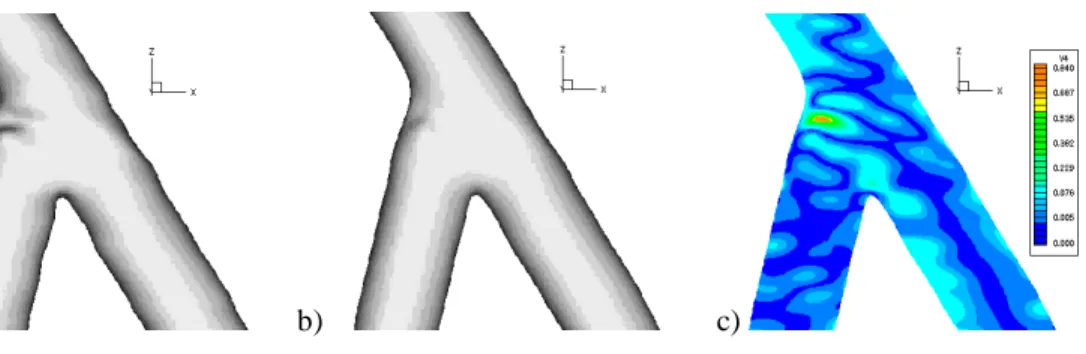
A flow solution, given boundary conditions from Doppler ultrasound and provided the geometry is adequately extended, can be obtained by the finite volume method (figure 3a). The accurate calculation of wall shear stress is very sensitive to mesh resolution and high-order p-type finite element techniques offer the potential of higher accuracy per computational effort compared to methods based on linear approximations [7].
a) b) c)
Figure 2. Triangulation of the zero level set of the implicit function: (a) Full surface. (b) Detail of polygonizer mesh. (c) Detail of enhanced quality mesh.
Our high-order mesh generator builds a boundary-conforming unstructured mesh of high-order spectral/hp elements by subdividing an initial coarse mesh of linear elements. The method is described in full detail in [8].
At present our mesh generator needs a parametric surface representation as starting input. Faced with the non-trivial problem of parametrizing an implicit surface, we adopt a semi-automatic procedure where the user interactively draws splines curves on the iso-surface triangulation and specifies a connectivity to build spline patches. Figure 3b shows that patches obtained in this way are close to the iso-surface but they do not cover it exactly and do not show more than position continuity through boundaries. Therefore, we project these patches on the iso-surface using an algorithm by Hartmann [9]. This provides a correct parametrization and achieves a better degree of continuity across patches.
The high-order mesh generator produces a surface mesh whose spacing is a function of Graft
Distal Proximal
a) b) c)
Figure 3. (a) Wall shear stress [Pa] computed by the finite volume method (FLUENT commercial package, Re 400, occluded proximal vessel). (b) Snapshot of the patches drawing procedure. (c) Projected patches.
the surface curvature. A viscous layer of prisms and tetrahedral elements constitute the volume mesh. Flow solutions are computed with a spectral/hp finite element solver [7]. The outlined reconstruction and mesh generation procedure is completely automatic but still requires the user to draw patches. Further work can proceed in two directions: either to automate the surface parametrization or to modify the high-order mesh generator to take a different initial geometry input.
a) b) c)
Figure 4. (a) High-order mesh. (b) Detail of mesh at inflow. (c) Wall shear stress [Pa] computed by spectral/hp solver (steady flow, Re = 400, occluded proximal vessel).
4. RECONSTRUCTION ACCURACY
We started our error quantification investigation by trying to reconstruct a known shape. We scanned two plastic tubes joined at an angle of 45 degrees. The shape acquired after segmentation, implicit function fitting and iso-surface extraction is depicted in figure 5(a). The reconstructed surface presents a dent near the junction region that is not part of the real model. This appears to be a field artefact caused by the magnetic properties of the glue used to join the tubes. Furthermore, the two reconstructed tubes do not show uniform circular cross-sections. A rapid and automatic way of eliminating these artefacts is treating the implicit function as a 3D image and applying a Gaussian filter. We do not allow the smoothed and the original surfaces to be further apart than one pixel. This is consistent with the MRI resolution.
a) b) c)
Figure 5. Smoothing: (a) Reconstruction of 2 tubes showing a dent at the junction. (b) Surface after maximum allowed smoothing. (c) Distance map [pixels] between smoothed and original surfaces.
5. GEOMETRIC FEATURES EXTRACTION
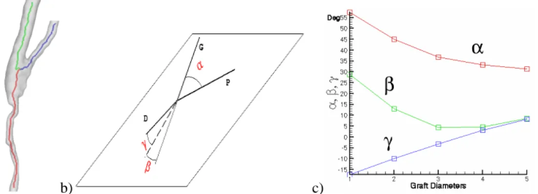
CFD calculations in anatomically correct geometries must be accompanied with identification of geometric effects on flow to provide surgeons with feedback on the anastomosis design. For example, surgeons are concerned with the angle between the grafted vein and the host artery. Since out-of-plane curvature strongly affects flow [10], some quantification of planarity must also be found. It is mandatory to define a centre line of each anastomosis. We adopt a fast three-dimensional six subiterations thinning algorithm to extract the skeleton (medial line) of reconstructed geometries developed by Palagyi and Kuba [11]. The method takes a 3D binary image as input, the space is then discretized into voxels and each voxel is given an intensity value of 1 if it is inside the blood vessel or 0 elsewhere. The algorithm iteratively thins the object by removing voxels on the external surface until an approximation of the medial line remains, as shown in figure 6(a). Since the thinning algorithm requires each voxel to know whether its 26 neighbours are part of the background, neighbourhood relations are built and updated during thinning so that the final medial line is made up of points and their connectivity. It is then natural to extract the junction point and the branches in an automatic fashion. Interpolating the branches with least squares straight lines we define a reference plane containing the graft and the proximal host vessel. Angles are measured between graft and proximal, planar component of the distal host vessel and graft, distal host vessel and normal to the plane. Angles change according to how much information is used in the interpolation in terms of how far interpolated points are from the bifurcation, figure 6(c). From the variation of the angles we deduct that the distal host vessel possesses a considerable amount of out-of-plane curvature, while the graft is approximately straight. This simple quantification can be applied in a statistical fashion to large data sets and hopefully be correlated with CFD results. Further work is aimed at expanding the parameter space by fitting higher-order curves to the medial line, for example a helix. This will permit to associate a value of torsion to each branch. We are also investigating efficient and accurate methods for calculating cross-sectional areas along the medial line. By changing the shape of the medial line and maintaining the same area distribution, we could perform parametric studies to investigate the effects of vessel curvature and torsion on flow.
6. CONCLUSIONS
We have described a semi-automatic variational reconstruction of geometry from MRI data. The reconstructed surfaces are used as input to CFD solvers and geometric analysis tools. The ability to associate flow features with parameters representative of
the vessel geometry is fundamental to perform parametric studies that might help surgeons understand how the design of an anastomosis influences its patency.
a) b) c)
Figure 6. (a) Medial lines. (b) Angles used for classification. (c) Dependence of angles on the distance of interpolated points from the bifurcation, expressed in graft diameters.
7. ACKNOWLEDGEMENTS
This work has benefited from the financial support from the Henry Smith’s Kensington Estate Charity. The Imperial College centres of Biomedical Visualization and Parallel Computing provided computational resources. We also would like to thank the staff at London St. Mary’s hospital involved in this study, coordinated by Prof. C. Caro and to Y. Papaharilaou for performing the MRI scans.
8. REFERENCES
1. Ouriel, K., Peripheral arterial disease, The Lancet, 358, 2001, 1257-1264.
2. Wootton, D. M. and Ku, D., Fluid mechanics of vascular systems, diseases and thrombosis, Ann. Rev. Biomed. Eng., 1, 1999, 299-329.
3. Turk, G. and O’Brien, J. F., Shape transformation using variational implicit surfaces, in Proc. SIGGRAPH99, 1999, 335-342.
4. Dierckx, P., Curves and surface fitting using splines, Oxford Science Press, 1993. 5. Duchon, J., Spline minimizing rotation-invariant semi-norms in Sobolev spaces, in
Constructive Theory of Functions of Several Variables, Lecture Notes on Mathematics, 571, 1977, 85-99.
6. Bloomenthal, J., An implicit surface polygonizer, in Graphics Gems IV, Academic Press, 1994, 324-349.
7. Karniadakis, G. E. and Sherwin, S. J., Spectral/hp element methods for CFD, Oxford University Press, 1999.
8. Sherwin, S. J. and Peiró, J., Mesh generation in curvilinear domains using high-order elements, Int. J. Numer. Meth. Engng., 53, 2002, 207-233.
9. Hartmann, E., Numerical parameterization of curves and surfaces, Computer Aided Geometric Design, 17, 3, 2000, 251-266.
10. Sherwin, S. J., Shah, O., Doorly, D. J., Peiró, J., Papaharilaou, Y., Watkins, N., Caro, C. G. and Dumoulin, C. L., The influence of out-of-plane geometry on the flow within a distal end-to-side anastomosis, ASME J. Biomech., 122, 2000, 1-10. 11. Palagyi, K. and Kuba, A., A 3D 6-subiteration thinning algorithm for extracting
medial lines, Pattern Recognition Letters, 19, 7, May 1998.
![Figure 3. (a) Wall shear stress [Pa] computed by the finite volume method (FLUENT commercial package, Re 400, occluded proximal vessel)](https://thumb-us.123doks.com/thumbv2/123dok_us/1669683.2729411/4.918.178.754.92.755/figure-stress-computed-fluent-commercial-package-occluded-proximal.webp)