IT 13 069
Examensarbete 30 hp
September 2013
Industrial Mobile Application
Design and Development
Transformer Monitoring Mobile Application
Jing Liu
Institutionen för informationsteknologi
Teknisk- naturvetenskaplig fakultet UTH-enheten Besöksadress: Ångströmlaboratoriet Lägerhyddsvägen 1 Hus 4, Plan 0 Postadress: Box 536 751 21 Uppsala Telefon: 018 – 471 30 03 Telefax: 018 – 471 30 00 Hemsida: http://www.teknat.uu.se/student
Abstract
Industrial Mobile Application Design and Development
Jing LiuThis thesis shows how mobile communication and information technology can be used on power industry domain. More specifically, the goal of this thesis is to design and develop a software concept demonstrator that gives operators a better possibility to check the status on ABB high voltage products, utilizing mobile devices, such as mobile phones and tablets.
At the beginning of this thesis, user study and information gathering was conducted at ABB Corporate Research Center, Västerås, Sweden and VB Energi, Ludvika, Sweden. According to the result of interview with both transformer monitoring experts and operators, a preliminary use case of the concept demonstrator was defined. By using evolutionary prototyping, the use case was continuously refined and rewritten, and user interface was designed in from sketches to high-fidelity prototype. Finally, a fully functional prototype, which used as software concept demonstrator, was
implemented on Android mobile phone platform and evaluated by both experts in ABB and end users in VB Energi.
The result of this thesis illustrates the current state-of-the art technologies on mobile device can be used in power industry to help the operators and engineers with their daily work. Usability, accuracy, interactivity are the most significant characters for this kind of industrial used software.
Tryckt av: Reprocentralen ITC
Sponsor: ABB Corporate Research Center IT 13 069
Examinator: Ivan Christoff
Ämnesgranskare: Iordanis Kavathatzopoulos Handledare: Jonas Brönmark
Contents
1. INTRODUCTION ... 1
1.1. PROBLEM STATEMENT ... 1
1.2. THE AIM OF THIS THESIS ... 2
1.3. DELIMITATION ... 2 1.4. THESIS OUTLINE ... 2 2. BACKGROUND... 3 2.1. ABOUT ABB ... 3 2.2. MOBILE APPLICATION ... 3 2.3. POWER TRANSFORMER ... 3 2.4. TRANSFORMER MONITORING ... 4 2.5. DEVELOPMENT TOOLS ... 4 2.5.1. ANDROID ... 4 2.5.2. SQLITE DATABASE ... 5 2.5.3. ACHARTENGINE ... 6 3. METHOD ... 7
3.1. USER-CENTERED DESIGN ... 7
3.2. USER STUDY AND INFORMATION GATHERING ... 7
3.2.1. CHECK USER‟S MENU ... 7
3.2.2. THE INTERNET ... 8 3.2.3. INTERVIEWS ... 8 3.2.4. QUESTIONNAIRE ... 9 3.2.5. MARKET STUDY ... 9 3.3. DESIGN PHASE ... 9 3.4. IMPLEMENTATION PHASE ... 9
3.5. TESTING AND EVALUATION PHASE ... 10
4. RESULT: ... 11
4.1. RESULTS FROM USER STUDY ... 11
4.2. USE CASE ... 12
4.3. USER INTERFACE DESIGN (SKETCHES -LOW FIDELITY- HIGH FIDELITY) ... 21
4.3.1. LOW-FIDELITY PROTOTYPE ... 21
4.3.2. GUI LAYOUT, FUNCTIONALITY AND APP COMPONENTS... 24
4.3.3. HIGH-FIDELITY PROTOTYPE & FINAL DESIGN ... 28
4.4. IMPLEMENTATION FUNCTIONAL PROTOTYPE DEMO ... 33
4.4.1. SMARTPHONE OPERATING SYSTEM CHOOSING ... 33
4.4.2. ANDROID ACTIVITIES ... 35
4.4.3. LAYOUT DESIGN ... 37
4.4.4. LIST VIEW AND ADAPTER (TRANSFORMER LIST, EVENT LIST)... 38
4.4.5. DATA FETCHING ... 41
4.4.6. POPUP NOTIFICATION ... 42
4.4.7. SETTINGS AND PREFERENCE ... 44
4.4.8. LOCALIZATION (LANGUAGE LOCALIZATION) ... 45
4.5. TEST AND EVALUATION ... 48
4.5.1. TEST AT THE EARLY STAGE OF DESIGN ... 48
4.5.2. TEST DURING THE IMPLEMENTATION PHASE ... 49
4.5.3. EVALUATION ... 51
5. CONCLUSION AND FUTURE WORK ... 54
5.1. CONCLUSION ... 54
5.2. FUTURE WORK ... 55
REFERENCES ... 56
APPENDIX A:QUESTIONNAIRE ... 58
1
1.
Introduction
This thesis shows how mobile communication technologies and modern mobile products, i.e. smart phones and tablet PCs, can be used on power industry domain. The current state-of-the-art technology in mobile devices supports greater processing power, more vivid display, and higher efficient information collecting method, which enhances interaction possibilities between human and machines. This technology can be used not only as consumer electronics products1, but also considered as great assistants on the industry area. The goal of this thesis is to design and develop an application which provides operators a better possibility to monitor the performance and status of ABB power transformers on their mobile devices.
1.1.
Problem statement
Power transformers are indispensable components of high-voltage equipment for power generation, transmission and distribution plants (Westman, Lorin, & A.Ammann, 2010) and their correct functioning is essential to the reliable operating of the power system. An unexpected interruption of power transformers can lead to unscheduled outages and power delivery problems, resulting in severe consequences for the stability of the electric grid. Therefore, it is necessary to monitor the operating condition and performance of power transformers in order to avoid or reduce unplanned failure. It also helps to save running costs by optimizing maintenance schedules.
Power transformers are placed in various geographical positions, many being located far away from cities and centralized electric grid control center. The operators can only get access to them via either physical visits to the site or remote connection equipment in secure network. Usually, one such operator is responsible for several transformers on different locations, which are often far from the others. Remote connection to transformers is an approach for monitoring, since warnings and alarms can be handled before the transformer protection system trips the unit. However these remote monitoring systems are built mainly to be accessed from PCs, but the operators are usually sitting in their cars, travelling between different sites, therefore they are unable to access the remote monitoring information.
Transformer monitoring on mobile devices, as an extension of the current monitoring system, could provide operators an access of the transformer status anywhere and anytime. The current state-of-the-art smart phones and tablet PCs equipped with powerful processors and large storage capacity allows applications operating on its platform. Meanwhile, the support of different kinds of network communication protocols enables the access to the Internet and the local network at anywhere there is mobile phone signal or hotspot (Wi-Fi). Moreover, the multi-touch screen and integration of GPS and camera provides more features of mobile applications. Therefore, mobile devices are able to be used in power industry domain and for transformer monitoring as a specific example in this thesis.
1
Consumer electronics are electronic equipment intended for everyday use, most often in entertainment, communications and office productivity. http://en.wikipedia.org/wiki/Consumer_electronics (visited 2013-06-16)
2
1.2.
The aim of this thesis
The goal of this thesis is to design and develop an application which provides operators a better possibility to monitor the performance and status of ABB power transformers on their mobile devices. To be more specific, as an extension of the current transformer monitoring system, this application should have a good consistency with it, which displays most of the significant information in a proper way. Moreover, the difference between mobile devices platform and traditional control room environment should be figured out and considered, especially when designing the user interface. The design and prototype should be based on user study, which guarantees the application comply with the real needs of operators.
1.3.
Delimitation
The output of this thesis work is a functional prototype that represents abundant concepts targeting ABB power transformer monitoring system on mobile devices. Due to the complexity of transformer monitoring system itself and different secure policies in Electricity companies and ABB, Only a subset of concepts are implemented in the functional prototype. Moreover, the functional prototype is only fulfilled on Android platform, since the market study illustrates Android has and going to have more markets.
1.4.
Thesis outline
Chapter 1: Introduction indicates the thesis objective, motivation for the project, the target
and delimitations.
Chapter 2: Background includes the brief introduction of ABB Company, the definition of
transformer monitoring, ABB transformer monitoring method, the usage of mobile application in general and technology adopted in this thesis.
Chapter 3: Method explains the methodology applied during different phases of the thesis
work.
Chapter 4: Result presents the results of user study, use case building, design of user
interface, implementation of the functional prototype and testing and evaluation.
Chapter 5: Conclusion and future work concludes the thesis and suggests some possible
3
2.
Background
2.1.
About ABB
ABB is a multinational corporation, global leader in power and automation technologies. It has about 145,000 employees in approximately 100 countries2.The current form of ABB Company is a merger of Allmänna Svenska Elektriska Aktiebolaget, Sweden and Brown, Boveri & Cie, Switzerland with over 120 years history.
ABB Corporate Research in Västerås is ABB‟s largest research center world-wide with more than 200 employees, mainly focusing on research and development of automation technology and power technology3. Software architecture and processes is one research under department of automation technology. This thesis work was conducted in ABB Corporate Research, Västerås, Sweden, which is a cooperation projects between power and automation technology, i.e. using IT solutions in power products domain.
2.2.
Mobile application
Mobile applications are a kind of software application design and developed for mobile device platform, such as smartphone and tablet PC. Native application and web application are the two major categories of mobile applications (Charland & Leroux, 2011). Even though they are different from both developers point view and user experience, they have some common characteristics:
-small size of software package, due to the limit of mobile device storage capacity -no heavy calculation, because of the limit of less powerful processor
-low battery consuming
-proper UI which fits the small size of screen and touch screen (phone keyboard) operation
2.3.
Power Transformer
A transformer is a static electrical device that transfers energy by inductive coupling between its winding circuits. A varying current in the primary winding creates a varying magnetic flux in the transformer's core and thus a varying magnetic flux through the secondary winding. This varying magnetic flux induces a varying electromotive force (emf) or voltage in the secondary winding4.
In electric power system, the generation of power in the generation stations is typically at medium voltage level (11-33kV), however, efficient and effective transmission over very long distance requires much higher voltage (etc,230kV), on the other hand , distribution of power
2
Brief introduction of ABB Company. http://new.abb.com/about/abb-in-brief (visited 2013-06-160)
3
ABB Corporate Research in Sweden. http://www.abb.se/cawp/seabb361/d2763491a6c93e61c1256ab800248c8f.aspx (visited 2013-06-16)
4
4
take places at much lower voltage, like several kV. Thus, power transformers can provide an efficient means of shifting voltage from one level to another (Bergen & Vittal, 2005).
2.4.
Transformer monitoring
Power transformers, which are often the most valuable asset in a substation or plant, are indispensable components of high-voltage equipment for power generation plants, transmission systems and large industrial plants. Unexpected failures cause major disturbances to operating systems, resulting in unscheduled outages and power delivery problems (Westman, Lorin, & A.Ammann, 2010). Such failures can be the result of poor maintenance, poor operation, poor protection, undetected faults, or even severe lightning or short circuits. Outages affect revenue, incur penalties and can cost a company its reputation and its customers.
Transformer monitoring is becoming an essential component of transformer management. It serves as an early warning system for any fault developing in the main tank and in the accessories, allowing an operator to evaluate the severity of the situation. Multiple transformers are connected to the operator‟s network and can be monitored from a local control room or from remote working stations. Sensors measuring dissolved gases, moisture in oil, oil temperature, load current for each unit, and ambient temperature send data to the system via analog signals. The interface provides exact status information by generating a model of the transformer and its working condition and then comparing the measured parameters with the simulated values. Discrepancies are detected and potential malfunctions and normal wear in the transformer and its ancillaries are indicated. The monitoring system also tracks transformer alarms, recording an actual event as well as the sequence leading up to the alarm to assist operators in determining the root cause.
The benefits of monitoring are substantial. A CIGRE study has shown that transformer monitoring can reduce the risk of catastrophic failures by 50 percent. Furthermore, it has been shown that early detection of problems can reduce repair costs by 75 percent and loss of revenue by 60 percent, and that annual cost savings equal to 2 percent of the price of anew transformer – i.e., approximately $40,000 to $80,000 – can be achieved (Boss, Lorin, Viscardi, et al., 2000).
2.5.
Development tools
2.5.1. Android
Android5 is a Linux-based operating system designed primarily for touch screen mobile devices such as smartphones and tablet computers. It is an open-source software stack for mobile devices, and a corresponding open-source project led by Google6.
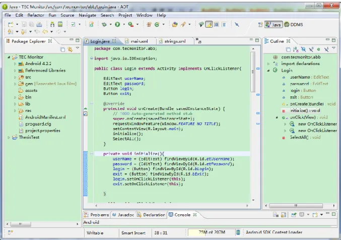
The Android software development kit (SDK) is a set of libraries and developer tools for building, testing and debugging Android apps. So as to build and develop an Android
5 Brief introduction of Android. http://en.wikipedia.org/wiki/Android_(operating_system) (visited 2013-06-16) 6
5
prototype, android SDK should be download and installed, and Java programming language is usually used for developing android app. (Applications are usually developed in the Java programming language using the Android Software Development Kit, but other development tools are available.)
Figure 1: A screenshot of Android software development kit
2.5.2. SQLite database
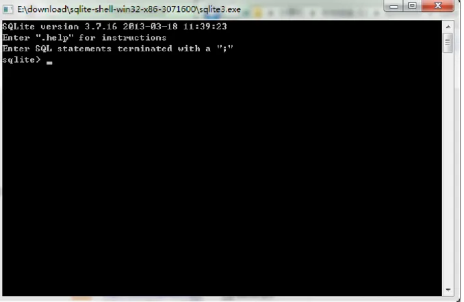
SQLite is light weight relational database engine, which is designed especially for embedded device7, since only little memory is required at runtime. The same as android, the source code for SQLite is in the public domain; therefore, it‟s free of charge for every developer and student. Most interesting, SQLite is embedded into Android by including the SQLite database management classes into Android APIs. Importing these classes into android APP project, without any database setup or administration, the application can build and manage its own private database.
SQLite has approximately 13 years history, and the latest version is SQLite 3. Compared with the other open-source database management systems, its execution time is faster. Besides, it supports transactions and uses B-tree implementation, since SQLite 2. SQLite can run under several operating systems, e.g. Windows, Linux, Unix, usually without any graphical user
7
6
interface. Some free tools for GUI are SQLite Administrator, SQLite Spy and sqlite-manager8.
Figure 2: A screenshot of SQLite3 command line interface (window operating system)
2.5.3. AChartEngin e
AChartEngine is a charting software library for Android applications running on mobile phones, tablets and other Android devices that developed with Android SDK version 1.5 and up. Currently, more than 10 different kinds of chart are supported9, including line chart which is used in the android prototype enclosed in this master thesis.
The reason why AChartEngine is needed here is that there is no existing java libraries for developing chart. Unlike the immediate use of SQLite APIs, a proper chart library needs either to be built or to be found for this thesis project. Since time is limited for this thesis work, and building a chart library is not an aim of this thesis work, the idea implementing a chart library was given up. After searching on the Internet and comparing several solutions of drawing charts, AChartEngine was chose for its good performance of charting display on the testing Android mobile phone for the project.
8 SQLite management tools. http://www.sqlite.org/cvstrac/wiki?p=ManagementTools (visited 2013-06-16) 9
7
3.
Method
This thesis was mainly organized by user-centered design method, together with software engineering principles, UML (use case), user interface design and test methodology. Specifically, different methods were selected and adopted in different phases, i.e. user study phase, design phase, implementation phase and test and evaluation phase.
3.1.
User-centered design
User-centered design (USD) is a kind of design process in which the end users, who are the experts in their work, are actively participating. It is focus on usability in each link of the system life circle. According to Key Principles for User-centred Systems Design (Gulliksen, et al., 2003), some more of the key principles of user-centered design are listed here:
Evolutionary systems development method should be used in USD;
The design should be represented easily understood;
Prototyping should be created and used to cooperate with the end users;
Evaluation should be conducted in each phase of design and development;
The design and development should be professional;
Usability experts should also be involved.
In other words, user-centered design is cooperation between system developer and usability expert concentrating on users‟ need that provided by real end users during the entire design and development process incrementally. The aim is to create usable interactive systems, involving analysis, design, implementation, evaluation, etc., and thus it guarantees the users and usability are focused the entire system lifecycle.
In this thesis work, the real end users should be the operators working in electricity companies with ABB power transformers. Practically, the electrical operators from one Swedish electricity company, VB Energi, were chosen as the end user for this user-centered design. Furthermore, the people working in software architecture group, especially, my supervisor Jonas Brönmark, are the usability experts for this thesis project.
3.2.
User study and information gathering
Six different approaches of information gathering were used during this diploma work, including checking user menu of ABB power transformer monitoring system, searching information on the Internet, interviewing experts in power transformer monitoring area, questionnaire survey to operators, investigating competitors and marker studying of mobile applications. The information gathered at this phase was used not only for evolving project plan, but for also software (mobile application) design, implementation, modification and evaluation.
8
The user‟s menu and technical guide of ABB transformer monitoring system are the written documents provided by ABB power transformer department in Sweden. The technical guide explains the hardware architecture of this monitoring system and installation guide, and the user‟s menu illustrates the user interface of monitoring software, which is a website, from the user point of view.
The user‟s menu of TRANSFORMER MONITORING SYSTEM is more interesting to this thesis delimitation, as the aim of this thesis work is to design and implement a mobile application with a better display of transformer status. However, as for the user‟s menu, it is obvious that the user interface of current transformer monitoring system is designed for big screens, e.g. PC or monitors in control room, and mouse-based control.
Although the user‟s menu is based on the design for currenttransformer monitoring system user interface (for big screen), it is a useful and valuable reference to this thesis work, since all the significant functionalities that need to be presented also by the mobile application are listed in this document. Nevertheless, not every feature on the website interface is necessary or can be displayed on the mobile devices, because of the limitation of these mobile devices, e.g. small size screen and touch screen. Therefore, some others approaches of information gathering are also need.
3.2.2. The In tern et
In 21 century, collecting information via the Internet is one of the most efficient and effective way of comprehending knowledge that is not familiar with. Some open encyclopedias and academic thesis database are good resource helping understanding the area out of someone‟s knowledge.
What is power transformer? How does it work? Why monitoring system is obliged to power transformers? …
These questions could be unfamiliar to a person with computer science background. However,
power transformer, monitoring system and reliability are the key words of this thesis. It is necessary to search for the definition and description of transformers with monitoring system and other related electrical devices and components.
3.2.3. Interviews
Interviews with power transformer monitoring specialists were conducted at ABB power transformer department in Ludvika, Sweden. In order to deeply investigate the architecture and functionality of current using transformer monitoring system, both hardware and information technology experts in TRANSFORMER MONITORING SYSTEM team were interviewed.
Interviews with operators in electricity company, performed at VB Energi in Ludvika, were also an indispensable part to information collection, because operators are the anticipate end user to the mobile app designed in this thesis work.
9
Interviews were not only conducted at the beginning, but also permeating the whole period of thesis work. The results were using for requirement analysis, new concept design, prototyping and evaluation.
3.2.4. Ques tionnaire
See Appendix 1.
3.2.5. Market stud y
The aim of market study is to select an appropriate mobile application platform for the functional prototype. The market study was carried out mainly by two methods. One is investigation of smartphone market share statistics published which is oriented global smartphone market. And the other one is market study within ABB Company and Electricity Company, in order to find out which smartphone operating system has the highest utilization among the target users.
3.3.
Design phase
The design phase could be divided into two steps, i.e. use case creating and evolutionary prototyping. At the beginning, a preliminary use case was defined based on the result of user study and interview with power transformer experts, which included the common tasks of an operator‟s daily work.
On the next step, evolutionary prototyping10 (Ozaki et al., 2003) was conducted to constantly refine and rebuild the use case. At the beginning of this thesis work, the understanding of the user requirements was limited, thus only the most well understood ones were built by low-fidelity prototyping. These preliminary design ideas were evaluated by user and expert to obtain feedback, modify the use case and add more features correspondingly. Moreover, this design and evaluation circle repeated during the whole design phase; accordingly, to the end of design phase, a relatively complete use case and high-fidelity prototype were accomplished, which were the base of the implementation. One advantage of evolutionary prototyping is that less time and effort was spent on ambiguous features, until them becoming clear.
3.4.
Implementation phase
Due to the delimitation of thesis, the outcome of this project is a fully functional prototype of a transformer monitoring application for mobile devices that satisfies the operator‟s needs. The implementation phase involved in this thesis is the implementation of this functional prototype, which is separate from the user interface prototype built on design face.
Hardware selecting was conducted before the implementation phase. According to the result of market study and user interview, Android mobile phone was chosen to be the hardware platform for this functional prototype. At the end of 2011, the latest released Android phone
10 Brief introduction of evolutionary prototyping.
10
model was Galaxy Nexus with the first use of Android 4.0 Ice Cream Sandwich operating system and a 1280*720 high definition screen. Java programming language was used for implementation, and Eclipse with Android Developer Tools plug-in 11 was selected as Integrated Development Environment (IDE). Besides, the implementation also involved database development with SQLite database engine.
3.5.
Testing and evaluation phase
In addition to the prototype evaluation and component testing during the design and implementation phase, release test and evaluation were conducted after accomplishment of the functional prototype. The aim of release test is to validate that the application meets its requirement of end user and emanate if every component of the application operates well together on the system level. Due to the limitation of time and resource, this test was first conducted by the developers, following the use case and test case accordingly. Afterwards, some transformer monitoring experts also conducted a “black-box” test on the functional prototype. Besides, scenario testing was adopted to assist the tester‟s work.
A short video was recorded and projected to both end user and experts on the user evaluation phase, which presented the basic functions and brief use instructions. Moreover, an integrated scenario was also related to the user together with a demo presentation of the functional prototype. After the presentation, the user and experts were guided to think aloud in order to provide the real feeling and every detail suggestion of the application.
11
11
4.
Result:
4.1.
Results from user study
According to the user study, there are six major features that should be included to this concept of mobile application for power transformer monitoring and some additional ones that could be involved.
First of all, this application should support multiple transformers monitoring. That is to say, one operator can obtain status information of different transformers at the same time. It shows from the interview with both the transformer specialist and operators working in Electricity Company that usually one operator has the responsibility for several sites (transformer substation) within a certain area, and in one site there usually is more than one transformer. Therefore, it is necessary to have multi-monitoring solution for operator‟s daily work. However, due to the limitation of electrical system monitoring devices network and security issues, there is no proper communication method ready-made between the monitoring servicer side and client side. It is also can be a good discussion in this diploma work.
Secondly, dynamic data fetching should be used in the design concept of this mobile application. Power transformers are expensive electrical facilities and one significant part of the whole electrical grids. Prompt information or warning and alarm messages of the status of transformers are essential to the health of them, prolonging their service life and saving them from being destroyed in emergencies. Moreover, records or logs of historical data is also interesting to operators, as from which a skillful electrical engineer can easily diagnose the problem in one transformer. Even though, for a new operator with limited work experience, this historical data can be used to calculate by an auto-diagnostic program.
Thirdly, it should be localized to proper languages and units. Although, English is the most popular and widely used language in the world, and temperature unit Degrees Celsius is most of countries in Europe and Asia, localization of software is totally meaningless. On the contrary, it can be important and necessary to use. People can obtain more information and more quickly from the message written by their mother tongue or language they are familiar with than the same message written by a foreign language or secondary language. For another reason, not every operator has a good language skill with foreign languages, especially, when reading technical terminologies in foreign languages. Similarly, not everybody can converse Degrees Fahrenheit to Celsius. Besides, the use of appropriate language, unit and time format, can result in less pressure and relaxed feeling of operators daily work, which is good for operators health and working higher efficiently.
Next, direct communication with control room should be a valuable assistant. In typical Swedish electricity companies, control room is a core part of the whole monitoring system of power facilities. Usually, there are 3-5 operators working together in one group. And 2-3 operators are responsible for inspecting the status of transformers on site and other devices in power grid, while the other operators stay in central control room. When an operator on site or
12
on the way to site notices some abnormal of transformer, he reports it immediately to his colleague staying in control room, before the final decision made in control room.
Figure 3: Photo of electricity company control room
Fifthly, user interface of transformer monitoring application should be consistent to the display of other devices monitored by operators. Taking error messages list for example, the operators are more familiar with checking error messages sorted by time descending order, because the same ordering method is used in all other devices.
Sixthly, security issue is one topic widely discussed amount all the interviewers, since power transformer is extremely critical to the whole electrical grid. In transformer monitoring system, this security is reflected in the information safety during the transmission of monitoring data.
Who can access to the monitoring database, and how to guarantee the authority using correctly, are two key questions need to be taken care of and discussed when designing the monitoring application on mobile devices.
4.2.
Use case
A use case describes a sequence of interaction between actors and system to accomplish a particular goal, which is widely used in system analysis to identify system requirements. The actor here can be a human user or an external system. Typically, a use case should include the following sections (Williams, 2003; Repond, Dugerdil, & Descombes, 2011):
13
Use case ID A numerical identifier to specific use case.
Use case name The name of the use case, indicating user‟s intention.
Use case description
Several sentences summarize the use case and explain concepts.
Pre-condition A list of conditions that must be met before the action of the use case. Post-condition A list of conditions that must be reached after the action of the use case.
Basic flow A sequence of interactions between the actor and system that follows the
main logic path.
Alternate flows An alternate logic path that could be resulted by the use case, e.g. an exception or an errors situation.
Expected result The acceptable results of the use case.
In this case, actor is the operators and system is the mobile application. And the interaction between them shows in the UML use case diagram (Booch, Rumbaugh, & Jacobson, 1998; Ambler, 2005) below.
14
Figure 4: UML use case diagram for transformer mobile monitoring system application
The information in this use case is intended for operators. Table 2: Use case for login
Use case ID UC-1
Use case name Log-in on the mobile monitoring application
Use case description
An operator should be able to login on the mobile monitoring application via using his or her own user name and password. Users without any authority should not be allowed to login on this application.
Precondition The operator has this App on his or her smart phone, before clicking on
the shortcut icon of this App.
Postcondition The operator successfully logs in on this App and start monitoring the
transformers on his or her responsibility.
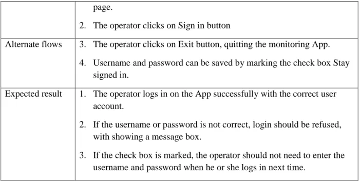
15 page.
2. The operator clicks on Sign in button
Alternate flows 3. The operator clicks on Exit button, quitting the monitoring App.
4. Username and password can be saved by marking the check box Stay
signed in.
Expected result 1. The operator logs in on the App successfully with the correct user
account.
2. If the username or password is not correct, login should be refused, with showing a message box.
3. If the check box is marked, the operator should not need to enter the username and password when he or she logs in next time.
Table 3: Use case for transformer overview list
Use case ID UC-2
Use case name Check the status of all transformers in the list
Use case description
The operator should be able to monitor several transformers categorized by several sub-stations. The identification of transformer and the current working condition should be obviously displayed to the operator.
Precondition The operator logs in on the App.
Postcondition After examining status of all the transformers, the operator moves on to
checking detailed monitoring information for one transformer that he or she is interested in.
Basic flow 1. The operator checks all the transformers in the list.
2. The operator is navigated to one transformer directly from the transformer list by one click.
Alternate flows 3. If the list of transformer is longer than length of the smart phone, the operator should be able to check the transformer at the end of the list by sliding the transformer list.
4. The composition of this transformer list could be altered by the operator himself or herself, since different operators is responsible to different transformers.
16
Table 4: Use case for real-time status monitoring of one transformer
Use case ID UC-3
Use case name Check detailed monitoring information of one transformer
Use case description
The operator should be able to examine all the significant parameters and data from censors in power transformer, which should be dynamic and fetching from time to time automatically.
Precondition 1. There is an access to network, e.g. via 3/4G or wifi.
2. The communication with monitoring server works properly.
Postcondition 1. One or more abnormal conditions in this current transformer are
discovered. (The operator could take measures on the transformer, or report it to Control Room.)
Basic flow 1. The operator enters the page presenting transformer general condition
and most important temperature page.
2. The operator goes to a specific page for examining condition information of tap-changer by clicking one icon.
3. The operator moves to a specific page for examining condition
information of Cooler group by clicking one icon.
4. The operator moves to a specific page for examining condition
information of gas sensor by clicking one icon.
Alternate flows 5. The operator can easily go to check different groups of transformer
condition data via a navigation menu or icon list.
Expected result 1. The operator could easily be navigated to appropriate condition data
group and check all of them.
2. If there is an abnormal event happening, the operator could be able to find it and do some investigation.
Table 5: Use case for historical data chart
Use case ID UC-4
Use case name Check historical data from a chart
Use case description
The operator should be able to check the historical data of some of the most important transformer condition data, for example, the load of transformer and tap-changer temperature. The historical data should be showed in one line chart with at most two different y-axis for using two
17
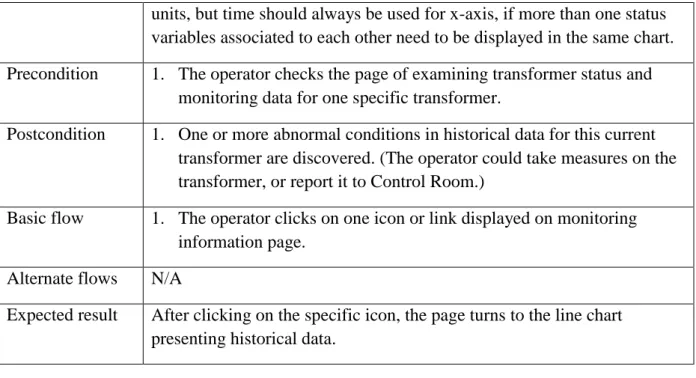
units, but time should always be used for x-axis, if more than one status variables associated to each other need to be displayed in the same chart.
Precondition 1. The operator checks the page of examining transformer status and
monitoring data for one specific transformer.
Postcondition 1. One or more abnormal conditions in historical data for this current
transformer are discovered. (The operator could take measures on the transformer, or report it to Control Room.)
Basic flow 1. The operator clicks on one icon or link displayed on monitoring
information page.
Alternate flows N/A
Expected result After clicking on the specific icon, the page turns to the line chart presenting historical data.
Table 6: Use case for chart display setting
Use case ID UC-5
Use case name Change settings of the chart‟s display
Use case description
The operator should be able to change the settings of the chart showing historical data for enabling or disabling the display of some status variables, changing line colors and setting time interval.
Precondition 1. The operator checks the page of historical data.
Postcondition 1. The line chart display has been altered based on the new settings.
Basic flow 1. The operator clicks on the setting icon on historical data page, before
the page changing to chart setting view.
2. The operator marks the status variables that he‟s interested with, and chooses line colors for each variable from the color picker.
3. The operator clicks on SAVE button to save the new setting and go
back to historical data chart page.
Alternate flows 4. After step 1 and/or 2 listing in basic flow, if the operator clicks on CANCLE button, the page will go back to historical data chart without any change.
Expected result The line chart historical data displays with the new settings which is latest set by operator.
18
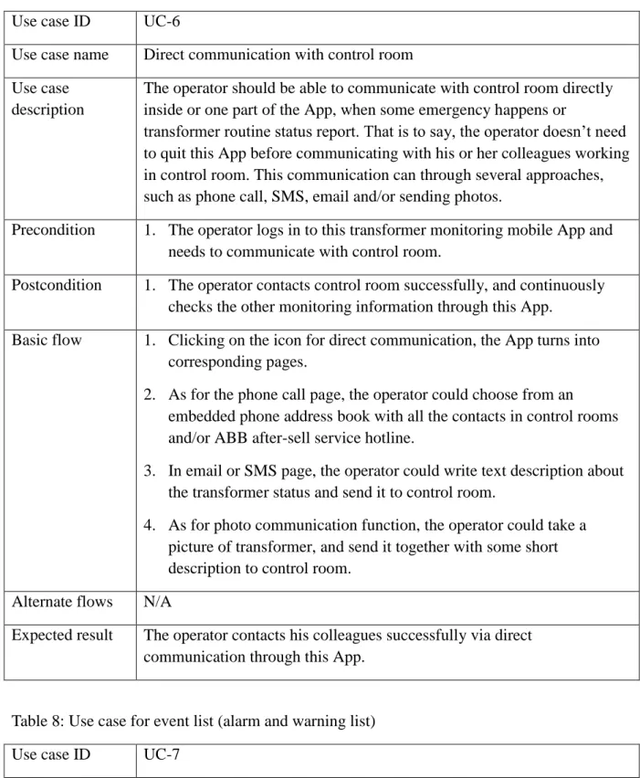
Table 7: Use case for direct communication with control room
Use case ID UC-6
Use case name Direct communication with control room
Use case description
The operator should be able to communicate with control room directly inside or one part of the App, when some emergency happens or
transformer routine status report. That is to say, the operator doesn‟t need to quit this App before communicating with his or her colleagues working in control room. This communication can through several approaches, such as phone call, SMS, email and/or sending photos.
Precondition 1. The operator logs in to this transformer monitoring mobile App and
needs to communicate with control room.
Postcondition 1. The operator contacts control room successfully, and continuously
checks the other monitoring information through this App.
Basic flow 1. Clicking on the icon for direct communication, the App turns into
corresponding pages.
2. As for the phone call page, the operator could choose from an embedded phone address book with all the contacts in control rooms and/or ABB after-sell service hotline.
3. In email or SMS page, the operator could write text description about the transformer status and send it to control room.
4. As for photo communication function, the operator could take a
picture of transformer, and send it together with some short description to control room.
Alternate flows N/A
Expected result The operator contacts his colleagues successfully via direct communication through this App.
Table 8: Use case for event list (alarm and warning list)
Use case ID UC-7
Use case name Alarm and warning list
Use case description
The operator should be able to check all the alarm and warning
information of transformer status, which is called event in transformer diagnose system saved in transformer monitoring database.
19
Precondition 1. The operator logs in on the mobile App.
2. There is at least one alarm or warning event happening, and recorded in the database.
Postcondition 1. A list of active events of the transformer displays to the operator.
2. Detailed event information shows, for example, event start time, event name and severity.
Basic flow 1. The operator clicks on event list icon on navigation bar or main menu
of this App. It shows a list of alarm, warning and other kinds of event classified by event type in time reverse order. The events displayed here in the list are only with simple transformer identification and timing information.
2. Clicking on the event name, the App turns into a page showing event
information dentally.
Alternate flows 3. The operator has another approach to enter event list page. After new
event occurred, the operator could clicks on event notification
displayed in the notification area at the top of the screen out side App. This is introduced in another use case Event Notification.
Expected result The operator examines event list and detailed event information
successfully.
Table 9: Use case for event notification
Use case ID UC-8
Use case name Event notification
Use case description
A notification is a kind of message that can be displayed outside App itself but in the notification area at the top of the screen. The operator could be able to obtain the notifications presenting event information when some new events happen. This notification could accompany with sound and/or vibration.
Precondition 1. This mobile transformer monitoring application should be logged in,
running foreground or background.
Postcondition 1. The transformer event page is displayed to the operator.
Basic flow 1. One or more transformer event notifications appear in the notification
area of the phone.
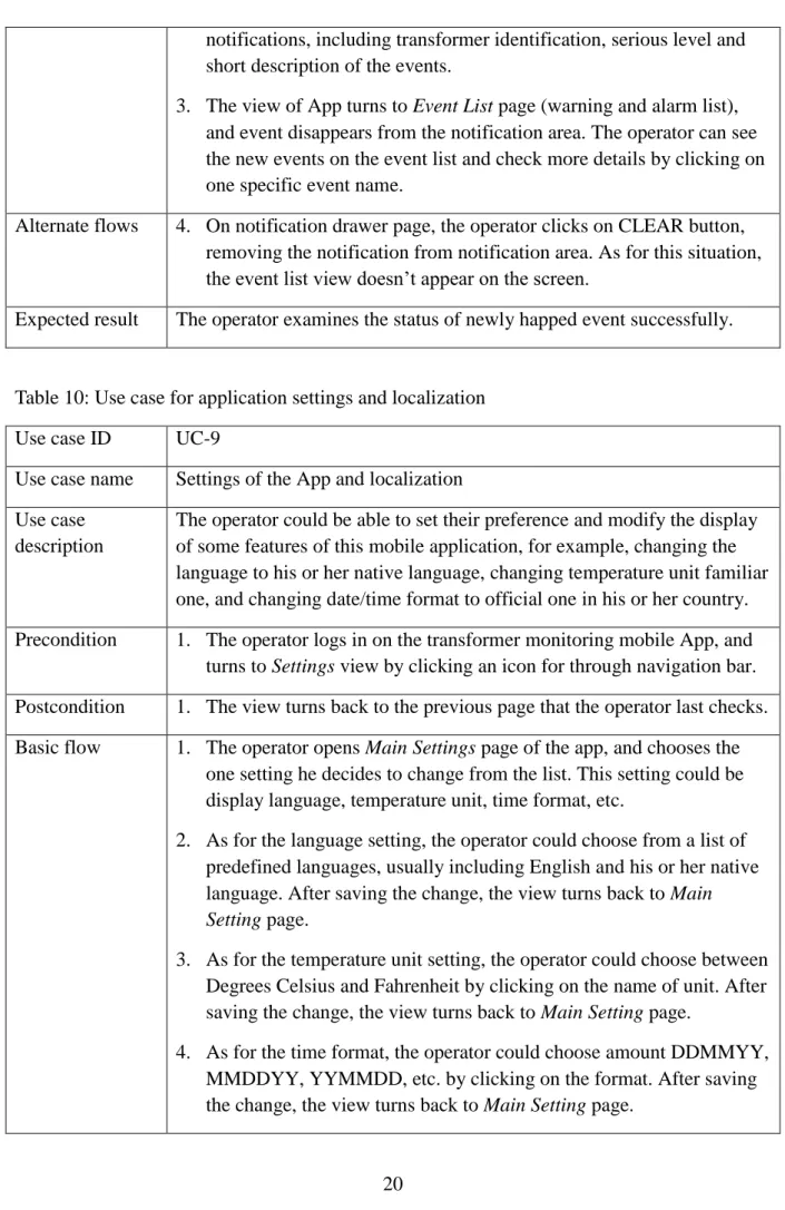
20
notifications, including transformer identification, serious level and short description of the events.
3. The view of App turns to Event List page (warning and alarm list), and event disappears from the notification area. The operator can see the new events on the event list and check more details by clicking on one specific event name.
Alternate flows 4. On notification drawer page, the operator clicks on CLEAR button,
removing the notification from notification area. As for this situation, the event list view doesn‟t appear on the screen.
Expected result The operator examines the status of newly happed event successfully.
Table 10: Use case for application settings and localization
Use case ID UC-9
Use case name Settings of the App and localization
Use case description
The operator could be able to set their preference and modify the display of some features of this mobile application, for example, changing the language to his or her native language, changing temperature unit familiar one, and changing date/time format to official one in his or her country.
Precondition 1. The operator logs in on the transformer monitoring mobile App, and
turns to Settings view by clicking an icon for through navigation bar.
Postcondition 1. The view turns back to the previous page that the operator last checks.
Basic flow 1. The operator opens Main Settings page of the app, and chooses the
one setting he decides to change from the list. This setting could be display language, temperature unit, time format, etc.
2. As for the language setting, the operator could choose from a list of predefined languages, usually including English and his or her native language. After saving the change, the view turns back to Main Setting page.
3. As for the temperature unit setting, the operator could choose between Degrees Celsius and Fahrenheit by clicking on the name of unit. After saving the change, the view turns back to Main Setting page.
4. As for the time format, the operator could choose amount DDMMYY,
MMDDYY, YYMMDD, etc. by clicking on the format. After saving the change, the view turns back to Main Setting page.
21
Alternate flows 5. Clicking on RETURN button, the operator could turn back to other
views without any setting changes.
Expected result The operator changes application settings successfully.
Table 11: Use case for application navigation
Use case ID CU-10
Use case name Navigation
Use case description
The operator could be able to navigate to different views via a menu page, a navigation bar and/or buttons, e.g. back button on the phone.
Precondition 1. The operator logs in on the App.
Postcondition 1. The app display turns to corresponding view as operator requests.
Basic flow 1. The operator enters menu page by clicking on an icon or through
MENU button on the phone, and sees a list of views that can be navigated directly from the main menu.
2. The operator clicks on the name or icon of the view requested.
Alternate flows 3. Clicking on CANCEL button on menu page or BACK button on the
phone, the operator could turn back to the page latest visited.
Expected result The operator navigates to the proper view he requires.
4.3.
User interface design (sketches -low fidelity- high fidelity)
4.3.1. Low-fideli ty prototype
After the use case definition and analyses, low-fidelity prototype was created to evaluate the usability of use case and provide the end-user, the operator, a direct experience with user interface. This low-fidelity prototyping could be divided into 2 steps, i.e. sketches and mock-up design.
The paper and pen based sketches is the simple, cheap and effective approach of prototyping (Sommerville, 2006, P382) which can be accessed without any training or special devices and software. Moreover, it is convenient for the communication between developers in the very early process.
Figure 5 shows some sketches drawn for the user interface design of this mobile application at the end of the first month. The analog meter design (1) and linear meter with 2-side limitations (2) were designed for presenting transformer status parameters, and the navigation quick bar was at the bottom of this view. In the sketch of transformer overview page (3), a
22
transformer list, several the most significant monitoring items and a brief historical data line chart were displayed together in the same view at that time. Sketch 4 shows a design of fast navigation between different transformers monitoring pages via a dope-down menu. Besides, displaying transformers or sites geographical location on the map (5) was also a substitute of transformer list page.
Figure 5: Paper and pen based sketches
These sketches were the first version of interface design. Although they looked very different from the functional demo presented at the end of the whole thesis work, they were significant and obligatory in the development process.
After discussing with end-user and other potential users with the sketches, some designs were changed and some other good ideas came up. For example, the analog display had been removed, since the operators though they would never use this feature due to a couple of reasons. First of all, there was no similar user interface at any part of monitoring system that they daily worked with; that is to say, analog design is inconsistent to other designs. So they were unfamiliar with reading analog meters. Moreover, because the analog icon itself took more space than the linear meter, less monitoring parameters could be displayed in the same view, which would lead more operations on touch screen for scrolling and switching pages.
23
Most importantly, it was difficult to present the warning and alarming limitation on analog meters, which was indispensible to monitoring display.
With those modifications and some new inspirations, the next step of low-fidelity prototype was designed via Balsamic mockups tool12 to obtain a better view approaching a real application‟s user interface.
Figure 6: low-fidelity prototype by Basalmiq mockup
Figure 6 shows some mockup screenshot for the user interface design of this transformer monitoring mobile application. Some of them inherited from the sketches with more new features, such as mockup picture (2) and (3) are from sketch (5) and (2) in figure 5. As it is shown in mockup screenshot (3), tabs were adding for switching between temperature monitoring page and other views. At the same time, more color coding signs were attached to the geography location of the transformers (2), for example, the red triangle representing for alarm situation, and tiny bull dot showing the operator‟s current location. In this step low-fidelity prototype, sketch (3) was spitted into two separate function page, i.e. transformer list (1) and historical data line chart (5) in figure 6, because there was too much information and the page was too crowded in the previous design. Besides, mockup picture (4) shows the warning and alarm list page for all the transformers‟ events.
12
24
Although Basalmiq mockup pictures has a better performance presenting different features of interface design than pencil and pen based sketches in some aspects, it still has its own limitations. Therefore high-fidelity user interface prototype and functional prototype of the application were carried out in the following work.
4.3.2. GUI l ayou t, functionality and APP componen ts
Graphical user interface is one of the most important sections to the design of this power transformer monitoring mobile App, which goal is to display the monitoring data to operators in the proper way that is clear, simple and efficient. As the same time, the interaction between mobile App and operator should be easy to master even without any learning or reading users‟ manual.
Different layouts are the basic components of graphical user interface for the mobile application. As from android, there are 5 basic layouts recommend by android developers API Guides nowadays, i.e. linear layout, relative layout, web view and list view, grid view with adapter. (There were more in history, but these five are the most popular and recommend to the developers by Android guide line.) By using the combination of those layouts together with other kinds of basic UI components, more practical user interface were constructed to this mobile application. In this chapter some of the typical GUI designs would be illustrated.
4.3.2.1. Customi zed li stvi ew
Listview is a kind of view group displays a list of scrollable items. Using a List Adapter, the list items, usually from a source such as an array or database query, are automatically inserted to the list.13 The simplest list is only a list of test strings. In order to develop a more attractive user interface, customized listviews were designed and implemented to this mobile application.
4.3.2.2. Listview with different icons
Adding different icons to each list items is the most common and effective customized listview. The icons can show the distinctions between items more intuitively than just text descriptions. List view with Icons is not only used in Android mobile application, but also almost everywhere on the current PC operating system and software. Two examples are the starting menu of Microsoft office operating system and menu page of Microsoft Word.
Icon listview design was used in several places of this mobile application, and here is an example of menu page. As it shows on the figure 7, there is an icon in front of each line of text, which clearly indicates what the following text represents for. All of this icon images are abstracted from the real image of according object, so the user can understand them only using his or her perception from daily life and work.
13
25
Figure 7: Listview with different icons for menu page design
4.3.2.3. Listview with s eparators
Although icon listview is a strongly supplement of traditional text listview, it is not sufficient in some situation, especially for some large lists. Separators could be an approach to improve the usability. Take phone address book for example, the contacts are categorized by the fist letter of their names, so that it is easier for users to find out one specific contact from thousands of them.
As for the design of this mobile application, listview with separators is also applied to many pages.
26
Figure 8: Listview with separators for transformer list design
According to user case UC-2, the display of power transformer should be classified by sites (transformer substation) name, since transformers belonging to one site are geographically located at the same place. It is convenient for the operator to visit them together at the same time.
4.3.2.4. Customi zed S eekbar
Similar as progressbar14, Seekbar15 can easily indicate the progress in one operation, but it has one extra draggable thumb on the bar. Usually, the draggable thumb can be touched and dragged to the left or right side of the bar to set the current progress level. However, the Seekbar can also be customized by disabling the draggable thumb, and alerting the display of the bar, in order to present more information in one Seekbar.
As shown in the figure below, the bar is divided into 3 parts, i.e. blue, gray and black, which represent 3 different state of “Hot-Spot LV temperature”, an important monitoring item of power transformer. At the same time, the thumb, which is an arrow in this picture, was disabled and only controlled by the monitoring data getting from servicer side. When the thumb lays on the blue part of the bar, it turns gray, which means this monitoring data is in the normal scope. If this monitoring temperature is higher than the alarm level, the thumb turns red and lays on the black part, accompanying with color change of the texts to red. It is a warning situation shown in this figure below.
Figure 9: Customized Seekbar design
4.3.2.5. Gridvi ew with differen t i con
Compared with ListView, the difference of GridView16 is it displays items in a two-dimensional, scrollable grid instead of one-dimensional. By using similar listadaper, the grid items can be automatically inserted to the layout. This is applied in this mobile application for a color picker mentioned in use cage UC-5.
This color picker is used for setting the line color displayed in historical data chart. After clicking on one color, the App turns back to the previous page with the new color setting.
14 Android ProgressBar. http://developer.android.com/reference/android/widget/ProgressBar.html (visited 2013-06-16) 15 Android SeekBar. http://developer.android.com/reference/android/widget/SeekBar.html (visited 2013-06-16) 16
27
Figure 10: Gridview with different icon for color picker design
4.3.2.6. Quick bar
Another navigation measure is the shortcut of a couple of icons list in quick bar at the top of each page. Because of the limit space in the quick bar, not all of the functional activities can be navigated by an icon list, but only the most frequently used and the ones for emergency need to be added there.
As shown in figure 11 below, there are only 5 icons displaying in the quick bar, which can be divided into 3 categories. The first one is using for controlling sliding menu; and the second one represents the event list, with a small digit in a red circle showing the number of activated alarm and warning events. The remaining there are the three ways of direct communication with control room, i.e. via email, photo message and phone call. It is obvious that sliding menu button is the most frequently used and should be accessed from each view.
Figure 11: Quick bar design
4.3.2.7. Preference settings with i mages and checkbox
Some features and displays of a mobile application can be modified by setting user preference, and the new characteristic after modification should be remembered automatically and permanently. That is to say, when the application restarted, it should present the new attributes as the last setting by the user. List, check box and edit text are the most commonly used approaches for setting user preferences. However, in some situation, they do not accommodate every need, or is not optimal to present some specific features. Therefore, some customized preference settings should be designed for those needs and features, according to the specification of developing each android mobile application.
28
The figure below shows the setting for historical data chart. The purple square to the left side represents the line color of “Peak Load” displaying in the chart. By clicking on it, the user can choose another color from the pop-up color picker and save it as his preference to this particular line color. Meanwhile, the checkbox next to the purple square is used for setting whether this “Peak Load” line is displayed on the chart or not. In this way, two different settings regarding historical data chart are combined together in the same view, which simplifies the operational process to the user.
Figure 12: Customized preference settings design
4.3.2.8. Color cod ing and avoid using unnecess ary colors
Appropriately using colors can not only promote its visual expression, but also transmit specific information to the user. For example, a black and white non-smoking poster uses a red cross on it to voice smoking is strictly forbidden here. It is obvious that the red cross is highlighted for presenting the meaning NO. However, if colors are overused, the user would miss this information among the colorful images. Avoiding unnecessary colors is one principle of user interface design.
There are only three colors are using in this application, except historical chart page. Gray represents for normal condition, while yellow and red represent for warning and alarm situation of the transformer respectively. So the abnormal events could easily be detected by the operator through this mobile application. As for the historical data chart view, the reason why more colors are needed is to display different lines in the same chart. Besides, the color used for lines are greatly different from each other and background color, so that the operator can distinguish the difference even though they use their smart in a poor lighting situation.
4.3.3. High-fid elity p rototype & final d esign
4.3.3.1. Databas e
Database is used for saving user login account and transformer list with identification information for each transformer, e.g. transformer ID, sub-station ID and IP address of TRANSFORMER MONITORING SYSTEM box. The reason it needed a database in this mobile application, which was client side, was to allow multiple user login and multiple monitoring transformer. According to the user study and information gathering, one operator is responsible for at list two sites (sub-station), and in each sites usually there are more than one transformer. Moreover, there are normally several operators in one electrical cooperate; therefore, it is necessary to setup one login account for each operator.
29
The aim of using splash page in the thesis project is to inform the user that this APP is loading now, and to present company and product information by this chance. It will disappear after loading process finishing, normally 3-5 seconds. Therefore, the splash should not contain too much information, or too complicated pictures, but use the images have the identical style with the company‟s image and keep consistency with the other products in the same series. This figure below is the design of splash page for this mobile app.
Figure 13: Splash page high-fidelity prototype design
The image used here is for ABB power transformer projects, so it is proper for this transformer monitoring mobile app. Moreover, the position, color and font are the same as the other ABB products advertisements and videos. Most important, ABB AB owns the copyright of this image, so it is free to use this commercial picture for ABB‟s product.
When splash page disappears, a login page shows on the screen. According to user study and information gathering, login page is needed to guarantee the data communication security, as every user could login onto the mobile app via his or her own user account.
4.3.3.3. Transformer lis t an d mul ti -transformer moni toring
Transformer list page shows a list of transformers grouped by different sites where the transformer locates at. In the demo, the transformers are just named by ID number and sites are named by letters, however, they can be changed to appropriate name that user used for their power transformers and sub-station site name. What is more, the images can also be changed to the ones can easily identify each transformer in the list, for example photos of
30
transformers. It is one of the most interesting part of this design that the use of color coding here, i.e. gray is used for normal transformer, yellow shows warning status of transformer and red shows some errors exist in that transformer. Therefore, the operator can easily find the transformer needed to check and take care of. If the list is longer than the length of smart phone screen, this list can be screw up and down.
Figure 14: Transformer list and transformer status high-fidelity design
4.3.3.4. Transformer status and tab vi ew
After clicking on one transformer, a list of the most essential monitoring temperatures and general information, such as aging and load of the transformer, are presented on the Transformer page “TEMP” page. On the top of this page (below quick buttons), there is the name of the current transformer the operator checking for, together with the site name where it located in. These names are the same as the ones used on transformer list page, in order to keep the consistency with each page of this mobile app. There are three tabs named “TEMP”, ”TAPC” and “COOLER” under the transformer name and its site name. “TEMP” tab is showed by default. By clicking on the names of these three tabs, the operator can easily switch among these three sub-pages and check three categories of monitoring information of one transformer. Besides “TEMP” tab, which explained above, “TAPC” tab contains the variables regarding tap-changer part of transformer, while “COOLER” tab is about the status of cooler groups of one transformer. Tap-changer and cooler group are two of the most significant components of power transformers, existing in almost all of them, and relative independence from the other parts of the transformer. Moreover, the status and variables descript these two components are indispensable for transformer monitoring. Therefore, two separated tabs other than general information tab are using on transformer page. Besides, if there are gas-censers in a power transformer, it is also need to add a new tab presenting all the information regarding gas.
31
Historical data chart shows the trend of important condition data, such as top oil temperature and load. A group of related trends were displayed in one chart with maximum two y-axis for two different units and an x-axis for time. Above the chart itself, there are several shortcuts, i.e. 1D, 2D, 1W, 2W and 1M, representing 1 day, 2 days, 1 week, 2 weeks and 1 month. When pressing one of these buttons, the line chart should zoom in or out to the corresponding time interval. Besides, there is a setting button on the right-bottom corner for changing line chart display settings as user‟s preference.
Figure 15: Historical data chart high-fidelity design
4.3.3.6. Alarm and warning list
Event list (Alarm and warning list) presents a list exception report messages collected from all the monitored transformers in different sites (transformer substation). In event list page, only the transformer ID, site ID, brief description, and start time of the currently active event are displayed. By clicking each event record, the users should turn to another page showing more detailed event information. Only three different colors are used for alarm and warning list, i.e. red for alarms, yellow for warnings and gray for other information. The event list page could be access to by clicking on the triangle sign with exclamation mark inside, and the digit at the top-right corner of the sign illustrates the number of active alarms and warnings.
32
Figure 16: Alarm and warning list high-fidelity design
4.3.3.7. Sliding menu
Sliding menu is increasingly popular nowadays, which is widely used in a couple of famous mobile applications such as Facebook. By clicking on the icon at the top left corner of each view of the application, the current view slides to the right part of the screen, but stops before moving outside the screen entirely, and the menu view appears on the left side of the screen. In general, it is a combination of animation and change between two different views. The benefit of sliding menu is both the menu view and apart of the previous functional page can be visible at the same time, and the switch between them just needs one click. Moreover the sliding process itself is a good interaction with users.
In this mobile application, sliding menu is also one indispensable of the whole concept design. All the functional activities can be navigated by this sliding menu.
33
Figure 17: Sliding menu design
4.3.3.8. Setting s
According to the result of user study, option settings function, especially the language localization, should be designed and developed in this transformer monitoring application. The design these settings should be as simple as possible, but some details must be handled carefully. Taking language setting for example, the operator can switching between languages by simply clicking on one radio button representing the language he prefers. Figure18 shows two screenshots under English display mode and Chinese display mode respectively, and it is obvious that any English word should be avoid appearing under English display mode.
Figure 18: Language settings design
4.4.
Implementation functional prototype demo
34
According to Gartner17, in the 3rd quarter of 2011, Android earned 52.5% market share, leading the smartphone sales market, while the market share of Symbian, iOS were 16.9% and 15.0% in the same period18 (Gartner, 2011). However, in the 3rd quarter of 2010, Android only had 25.5% smartphone sales to end users, showing a fast growth of Android OS market.
Figure 19: Worldwide mobile device sales to end users by vendor in 3Q2011, from Gartner
Figure 20: Worldwide mobile device sales to end users by vendor in 3Q2010, from Gartner
One reason choosing Android platform for the functional prototype is that it earns the largest market worldwide. Another reason is that based on the user survey, most of the operators in VB Energi, Ludvika and ABB transformer experts use Android phones. Therefore, the functional
17 An American information technology research and advisory company 18
Source: Gartner (November 2011). http://www.gartner.com/newsroom/id/1848514 (visited 2013-06-16)
53% 17% 15% 11% 2% 3% 1% Android Symbian iOS Research In Motion Bada Microsoft Others 25% 36% 17% 15% 1% 3% 3% Android Symbian iOS Research In Motion Bada Microsoft Others
35
prototype can be easily installed on their smartphones for testing and user experience evaluation.
4.4.2. Android Activi ti es
An activity is a fundamental android application component which provides user a window containing the user interface of this application19.Normally, one application has one or more activities that loosely bound to each other, and among them one activity is the main activity, which is the first one after launching. One activity can start another one, and only one activity can be on run mode. When the new activity starts, the previous activity is stopped. This is handled by a back stack, which always push the current running activity on the top of the stack.
Figure 21 shows the lifecycle of activity from created to destroyed.
Activity launched onCreate