Disruptive Effects of Electromagnetic
Interference on Communication and
Electronic Systems
James Burrell
Research project submission for the partial fulfillment of the requirements for the degree of
Master of Science in Telecommunications
Advisor
Dr. Jeremy Allnutt
Director, M.S. Telecom Program George Mason University
School of Information Technology & Engineering April 2003
Table of Contents
Abstract... 3
Introduction... 4
Wireless Communication Link Parameters ... 5
Radio-Frequency Spectrum ... 5
Free-Space Segment... 6
Atmospheric Effects... 7
Antenna Properties... 9
Electronic and Electromagnetic Interference... 13
Noise and Interference ... 14
Electromagnetic Interference (EMI) ... 15
Additional Propagation Affects ... 18
Factors Affecting Satellite Signals... 19
EMI Countermeasures ... 19
Source Elimination... 20
Grounding ... 20
Filters ... 20
Shielding ... 20
Directed Energy Interference Sources ... 21
Directed Energy Sources... 21
Radio-Frequency Directed Energy Devices... 23
High-Power Microwave (HPM) Directed Energy Devices ... 24
Directed Energy Protection Issues ... 27
RF Directed Energy Interference: Effects on the Global Positioning System (GPS)... 27
Overview of the GPS System ... 28
Applications of the GPS System... 29
Vulnerability To Disruption... 30
Summary ... 31
Abstract
The vulnerability of wireless communication links from sources of interference is increasing. The increase in the number of transmission systems, band congestion and intentional interference activity represent significant threats to the normal operation, availability and reliability of these wireless systems. This research paper will initially address conventional sources of interference that affect these systems, progress to the new threats posed by intentional interference and directed energy sources, and present a practical example of the effects of intentional disruption on a global satellite navigation system.
Introduction
The increasing demand for data communications and connectivity has resulted in the development of innovative methods to satisfy current and emerging communication requirements. The path on which data travels from its source to its destination is described as a communications link.
The primary sources of interference that effect wireless communication systems are electromagnetic in nature and can result in the magnetic and radio frequency
disruption or intermittent failure of electronic, communication and information systems. The inherent physical, technical and mechanical design parameters associated with wired data links (i.e. fiber optic or cable) often offer a level of immunity from noise and
interference sources. In addition, wired media has certain attributes that can limit the effect of noise and interference which adversely affect wireless data links.
Wireless communication data links utilize free-space propagation and are subject to interference and signal disruption from a broad spectrum of sources. This represents one of the most significant challenges for designers of these systems, whereas it is difficult, and in some instances impossible, to isolate the transmission media from sources of electromagnetic and radio frequency interference. Wireless communications technologies utilize a broad range of the electromagnetic spectrum, to include high frequency, very high frequency, microwave, and optical transmission frequencies. The effects of noise and interference are different at different segments, or frequencies, of the electromagnetic spectrum. In order to address these concerns, significant consideration should be given to the design of wireless data link parameters that adequately address
communication requirements and the issues related to signal interference and disruption. The consideration of potential interference sources during the design of these systems can offer considerable effects on data link connectivity, reliability, and data rates.
The increased reliance on wireless networks data networks and wireless network segments introduces an additional vulnerability in relation to network operation and survivability. These wireless systems are subject to increased band congestion
interference and the possibility introduction of an intentional interference source. The ability to transmit directed energy to critical wireless nodes can result in the temporary or permanent disruption of network connectivity and services.
Wireless Communication Link Parameters
Data link design parameters specify the engineering requirements to ensure the proper operation of a particular wireless communication segment.
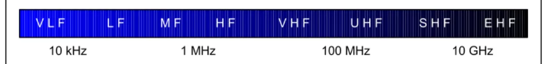
Radio-Frequency Spectrum
These wireless segments operate at frequencies that span the entire radio-frequency spectrum, as illustrated in Figure 1.
V L F L F M F H F V H F U H F S H F E H F
10 kHz 1 MHz 100 MHz 10 GHz
Free-Space Segment
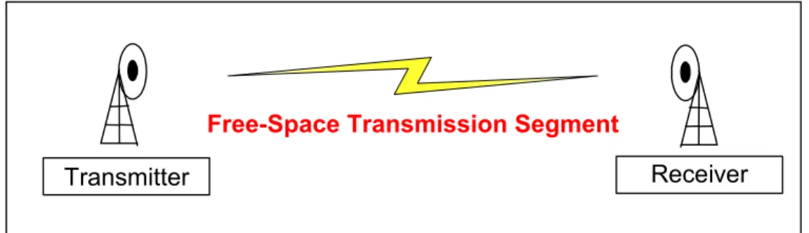
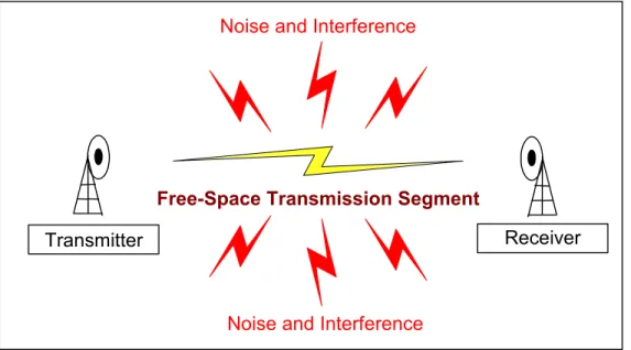
The principle of data link design is to specify power, frequency and antenna requirements to ensure the reliable conveyance of data across the wireless data link, while accounting for the effects of attenuation, propagation, and noise relating to the free-space transmission segment, as illustrated in Figure 2.
Free-Space Transmission Segment
Receiver Transmitter
Figure 2 - Wireless Communication Link
The principal link parameters include the operating frequency of the link, the output power, and antenna parameters. In certain circumstances, increasing output power levels can reduce certain aspects of wireless link interference, but this method can cause unnecessary interference to other electronic and communication systems, and is not practical for mobile devices with finite power sources.
The equation used to calculate free-space transmission loss is given in Equation 1. The distance and frequency variables in Equation 1 are directly proportional and an
increase in the value of either of these parameters will increase the value of the free-space loss.
L(db)= 32.5 + 20 log10 d + 10 log10 f
Where
L is the free-space transmission loss in dB
d is the free-space transmission distance in kilometers f is the frequency in Megahertz.
Equation 1 – Equation to Calculate Free-Space Transmission Loss
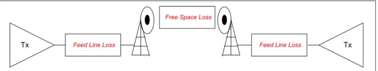
The principal values used to determine the overall loss value for a wireless communication link include the free-space loss, in addition to any feed line loss at the transmitting and receiving ends of the link, which can be negligible when compared to the free-space segment losses. A diagram of the overall system loss values is illustrated in Figure 3.
Feed Line Loss
Tx Feed Line Loss Tx
Free Space Loss
Figure 3 – Wireless System Loss Values
Atmospheric Effects
There are numerous factors that effect radio wave propagation, which include transmission power, antenna gain, attenuation factors, and noise. In addition, there are
ionospheric and tropospheric conditions that also have a dramatic effect on the propagation of radio transmission through free-space.
High-Frequency (HF) Propagation (3 MHz – 30 MHz)
The transmission of HF signals for distances greater than approximately 100 miles depends on sky wave propagation, due to the ionization levels that exist in the ionosphere. In most instances, HF communications occurs along the shortest path between two stations in which the signals propagate using the lower atmospheric region.
The effects of the ionosphere on signals in the medium and high-frequency regions are more pronounced than at VHF/UHF ranges and are refracted gradually over a considerable vertical distance. The maximum usable frequency (MUF) is the highest frequency supported for reflection by a specific ionospheric layer at a given frequency. The ionization levels of the ionosphere change constantly due to naturally occurring conditions. This is an important consideration when operating in the HF region, since failure to adjust the MUF for a change in atmospheric conditions will effect signal propagation.
VHF/UHF Propagation (30 MHz – 300 MHz / 300 MHz – 3 GHz)
The transmission of VHF/UHF signals depend on ground wave propagation and almost always follow line-of-sight paths, which requires no obstructions between the transmitting and receiving stations. The distance limitations association with this frequency range is primarily a function of the antenna height of the transmitting and receiving antennas.
The calculation of free-space transmission loss is the primary consideration in effective satellite communication systems. The earth station can offset a portion of these losses by employing an antenna with a larger effective area, higher antenna gain, and higher transmission power. In addition, noise levels from terrestrial, man made, and cosmic sources can also interfere and negatively effect signal propagation. Higher frequencies are somewhat immune to these effects, but they have higher free-space transmission losses.
Antenna Properties
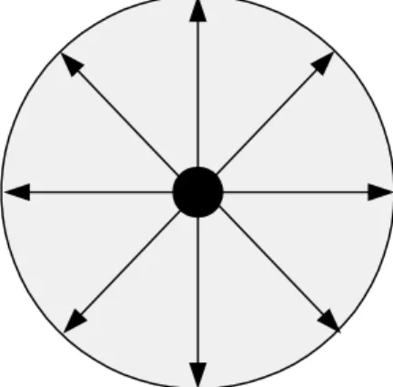
The antenna properties of a wireless transmission system have a significant effect on the overall performance and operating distance of these systems. An isotropic antenna source is used to model antenna transmission calculations in many wireless systems. The basic operating principal of an antenna is that a voltage applied to the antenna causes the flow of current along the antenna segment. This principal applies to both transmitting and receiving antennas. The parameters of an antenna that are of particular interest in wireless transmission systems include antenna gain, directivity, and bandwidth. The radiation pattern of a transmission antenna is typically modeled using an isotropic radiator. This model assumes that an equal amount of transmission energy is radiated equally in all directions. An illustration of an isotropic radiation pattern is given in Figure 4.
Figure 4 – Isotropic Radiation Pattern
For an isotropic antenna, the power radiated per unit solid angle is calculated using the equation:
Pi = PT / 4π
PT
Distance R
Area (A) = A / R2
The actual power received on an actual antenna is the value of multiplied by the value of Pi multiplied by GT.
The electric field strength at the receiving antenna is the calculation of the received signal power at the receiving antenna taking into account loss, noise, and interference sources. The equation used to determine the electric field strength of a receiving antenna is given in Equation 2.
E (V/m) = √ 30 PT GT d
Where
PT is the average power (isotropic source) GT is the transmitting antenna gain.
Equation 2 – Equation to Calculate Received Electric Field Strength
Antennas designed for to radiate radio frequencies are defined by their respective
gain and directivity. Gain refers to the characteristic properties of the radiation power an antenna to distribute higher power in a particular direction. Directivity refers to the measurement of the ability for an antenna to direct energy in a specific direction
The directivity of an antenna is often specified by its beam-width (BW). The beam width of an antenna is the angular displacement between points on the main lobe where the power density of the main radiation lobe drops to a one-half power (-3db) power density [1]. The degree of a particular antenna pattern is concentrated into a beam is known as directivity of the antenna, and is expressed as the quotient of the maximum radiation intensity divided by the average radiation intensity, based on the antenna radiation pattern and is defined by Equation 3:
D = Pmax / Pavg Where
Pmax is the maximum power flux radiated Pavg is the average power flux radiated.
Equation 3 – Equation to Calculate Antenna Directivity
The 3db beam-width of an antenna can be calculated by substituting frequency and distance values into Equation 4.
θ3db = 70 ( c / f D )
Equation 4 – Equation to Calculate Antenna Beam-width
The receiving antenna is positioned so that it will receive the maximum power from the desired signal transmission. The power at the receiving antenna can be calculated using Equation 5.
PR = ( PT GT ) ( 1 / L Free Space ) GR
Equation 5 – Equationto Calculate Power at a Receiving Antenna
The frequency, free-space loss, atmospheric attenuation, and transmit and receive antenna parameters all represent important variables in the wireless data link design. Their individual and combined properties can have considerable affect on the effective
operation of wireless data links and their susceptibility to electronic and electromagnetic interference.
Electronic and Electromagnetic Interference
The presence of electrical contributes to the surrounding levels of electrical and electro-magnetic noise and interference. The increasing demand and dependence on The use of electromagnetic transmission systems for information technology applications has enabled revolutionary communications capabilities to include cordless
communication devices, wireless networking, and satellite communication systems. As the number of these devices increases, there is an increase in electromagnetic radiation within the segments of the electromagnetic spectrum in which these systems operate. These emissions have the potential to interfere with the normal operation and function of electronic communication links and systems.
The condition of electromagnetic energy disrupting the normal operation or function of electronic devices is known as electronic interference (EI). The source of EI can be categorized as environmental (naturally occurring), incidental or intentional. The effects of EI can be significant regardless of their source, however, engineering design and other considerations that can be used to limit the impact and disruption of EI on electronic, communication and information systems.
The following terms are used to describe distinct parameters that relate to the topic area: [ARRL]
Noise – A signal that interferes with the desired signal in electronic communications or systems.
Interference – Unwanted interaction between electronic systems.
Electromagnetic Interference (EMI) – An electrical disturbance that interferes with the normal operation of electronic equipment.
Radio-frequency Interference (RFI) – Is a subclass of EMI that relates to the interference caused by a source of radio-frequency signals.
Free-Space Transmission Segment
Receiver Transmitter
Noise and Interference Noise and Interference
Figure 5 – Noise and Interference on Wireless Communications Link Noise and Interference
Noise and interference are present at all frequencies, vary according to a specific frequency band, and affect the speed, accuracy and range of communications.
Noise and interference occur across the entire radio frequency (RF) spectrum. The presence of noise and interference can have detrimental effects on the effectiveness and availability of communications systems. Noise is the presence of unwanted energy levels in the same frequency band as the communication systems or equipment. Noise energy is typically produced from sources other than electronic or communication
systems and is often difficult to minimize and particular noise levels may be hard to predict.
Interference is the energy levels introduced by electronic or communications systems that have a detrimental effect on other systems. There are two principal type of interference that affects these types of systems, internal and external interference. Internal interference is energy generated internally by the electronic device, whereas external noise represents levels of energy that are generated by external sources. The effects of external noise can sometimes be minimized by shielding, however internal interference is very difficult, if not impossible, to mitigate due to the close proximity of the interference source to the affected electronic system and may have been avoided at the engineering design phase.
Electromagnetic Interference (EMI)
The fundamental concept of electrical and electromagnetic interference involves an emanating source and an affected device or system. The transfer of energy between systems can occur through radiation, conduction, or induction. The actual transfer of energy is facilitated respectively through a transmission path, conductive path, or through magnetic coupling.
The interference that affects wireless communication links is typically the result of radiated or conductive energy transfer. The condition of a conductive affect occurs when the signal is picked-up by a conductor attached to the affected system.
The sources of EMI can be generally separated into the following categories: • Incidental interference
• Intermodulation distortion • Spurious Emissions
• Adjacent Channel Interference • Environmental Interference • Band Congestion
• Intentional Interference (Jamming
The ability of electronic systems to operate reliably in the presence of interference is known as electromagnetic compatibility (EMC). There are several ways that EMI can transfer from a source to the victim: radiation, conduction, and induction.
Incidental Interference
The situation when a device is unable to distinguish a desired signal due to the reception of a strong signal which is not the desired signal. This can often be the result of issues relating to the circuit design, shielding requirements which can lead to the inability to reject these unwanted signals that occur within and out-of-band in relation to the desired signal. Incidental Interference
The operation of electronic devices causes the emission of electromagnetic radiation of different levels. These devices include wireless devices, mobile phones and radar systems. Incidental EI is a major concern with both medical devices and airplane electronics, where interference between devices that are not electromagnetically
compatible with each other can have potentially devastating effects. [9]
External noise sources can be electromagnetic or electrical in nature. Noise from electromagnetic sources can vary in their intensity and period, whereas electrical sources are constant in nature.
Spurious Emissions
The transmission of signals that are outside the prescribed frequency band of a transceiver are considered spurious emissions and can be in the form of discrete
narrowband signals or wideband noise. One common occurrence of spurious emissions involves harmonics at multiples of the fundamental frequency.
Adjacent Channel Interference
Adjacent channel interference may be caused by receiving a strong signal at a relatively close frequency to the selected signal and can often be minimized through the use of proper transmitter and receiver design techniques.
Band Congestion
The overcrowding of frequency bands in addition to modulation techniques, transmitter design and receiver design can cause significant interference between devices operating within shared or closely spaced frequency bands.
Environmental Interference
The environment in which we live has natural sources of electromagnetic
radiation. These environmental radiation emissions can interfere with the operation and effectiveness of electronic systems and communication data links. Examples of
environmental sources of EI are lightning and solar energy.
The intentional emanation of energy to cause noise or interference to another device or electronic system is known as ‘jamming’. The effectiveness of conducting this type of activity depends on numerous
The intentional disruption of electronic or communication systems is a topic that must be considered in data communication link design, especially with the increased reliance on wireless communication technology as the primary communication medium for critical systems. A practical example of intentional EI is a technique known as jamming. This condition is the created through the intentional emission or reflection of electromagnetic energy or signals for the purpose of disrupting the electromagnetic signals of another system. This technique can be employed for a narrow band or wide band portions of the electromagnetic spectrum. The ability to effectively jam a signal or group of signals typically requires the use of a high-power transmitter which produces a signal that is stronger than the target signal. The susceptibility of the receiver is also an important factor in the amount of transmission power necessary to effectively jam or disrupt a communication link or system.
Intentional interference has the capability of disrupting radio communications, radar and radio navigation systems. The transmission of RF energy at a specific frequency or frequency band of sufficient levels can essentially overpower or cause significantly reduced signal integrity
Additional Propagation Affects
Multipath - The condition when multiple copies of an original signal are received. These multiple signals have different amplitude and phase variations which can appear as interference to a receiver.
Reflection – The result of a signals reflecting from objects in the signal path.
Factors Affecting Satellite Signals
There are additional signal propagation factors that affect the performance and overall reliability of a wireless communication link, which includes:
Ionospheric Attenuation Tropospheric Attenuation
The modulation technique used for a wireless transmission system can have a significant affect on the overall performance of a wireless transmission system and its susceptibility to certain types of noise and interference. There are different modulation techniques that offer superior noise immunity and as a result offer improved system performance.
EMI Countermeasures
There are a number of possible countermeasures to counter the effects of
interference with electronic and communication systems. The corrective action may be very complex if the interference is a combination of multiple sources.
Source Elimination
An effective technique to eradicate interference is through identification and elimination of the source. In theory, this represents arguably the most effective of any measures, but is not practical in most situations, whereas this would require the source to be periodically or permanently disabled from operation.
Grounding
A grounding point represents a common reference point for a device or multiple devices that functions to ensure the safety or the equipment and operator, and its effects provide some immunity to noise and interference. Certain transmission and other electronic equipment require adequate grounding to ensure proper operation. The conductor used to ground the equipment should be the shortest necessary length to avoid a ground loop condition. This could result in energy transfer through conduction to connected devices.
Filters
The use of filters allows selected frequencies to pass through to the connected device, while rejecting or attenuating any frequencies that are outside the filter specifications. Examples of filters include low-pass, band-pass, and high-pass. Shielding
An effective manner used to minimize, and in some instances eliminate, EMI is to effectively shield components from interaction with electromagnetic energy. This
technique is often expensive and causes major design engineering challenges, especially to fully shield a device, which requires that conductive material completely enclose the
equipment or circuitry. Any separation in the shielding material reduces the effectiveness of the shielding technique.
Directed Energy Interference Sources
The term directed energy applies to the production of a beam of concentrated electromagnetic energy or atomic or subatomic particles [8].
Directed Energy Sources
Directed Energy (DE) devices provide a significant threat to electronic and communication systems through the emanation of electromagnetic energy in the form of a series of pulses or as a continuous wave transmission. These devices typically cause an electromagnetic disturbance that can under certain conditions cause the interruption, obstruction, or degradation in the performance of electronic and communications equipment.
The most destructive of all sources is the electromagnetic pulse (EMP), which is designed to permanently disable electronic devices within the reception area of the emanated signal. The generation of this type of electromagnetic radiation can be from a nuclear or non-nuclear source, which results in electric and magnetic fields that couple with electronic systems and produce damaging current and voltage surges.
The majority DE devices operate in the 500 MHz to 30 GHz region of the electromagnetic spectrum, as depicted in Figure 6.
V L F L F M F H F V H F U H F S H F E H F
10 kHz 1 MHz 100 MHz 10 GHz
Figure 6 - Typical Operational Frequency Range of Directed Energy Devices
A specific application of these devices is for military applications. These devices, which are capable of adversely effecting the operation of these electronic systems, are an evolution of electronic warfare systems that employed less invasive jamming techniques. The principal requirement for a DE device is the required power to generate necessary power for operation. The operation of high-power DE devices requires significant power and cooling requirements and can be mounted in a vehicle or airborne platform.
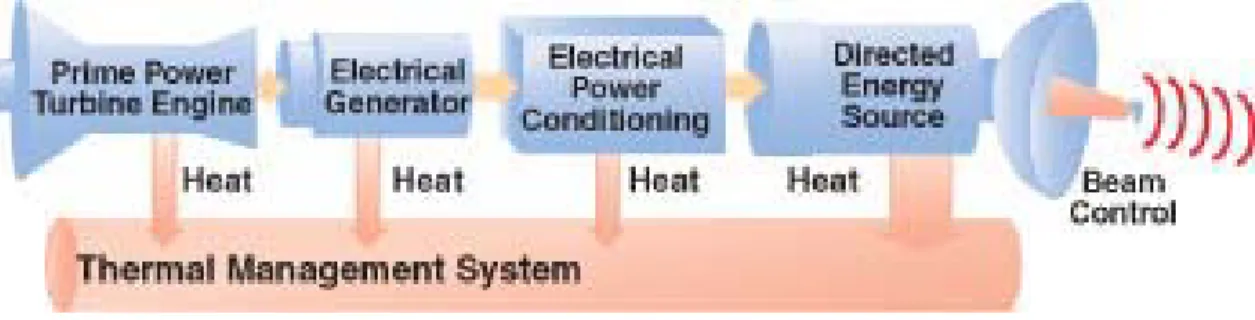
A system block diagram of an electric airborne DE device is given in Figure 7.
Figure 7 - System block diagram for an electrically powered airborne DE system
(Source: AFRL Propulsion Directorate, Power Division, Electrical Technology Branch, Wright-Patterson AFB OH)
The ability of these devices to cause a temporary or permanent malfunction or failure of a targeted system is a result of the high-power density and energy density that
can disrupt normal operation of electronic systems. The use of such devices in the proximity of critical electronic systems could have catastrophic results, such as with the power delivery system, transportation system (to include navigation and air traffic control), emergency services, and financial and banking services.
Radio-Frequency Directed Energy Devices
Radio-frequency DE devices typically are designed to transmit short, high-power pulses of electromagnetic energy to short or long-range targets. These transmissions can have significant damaging effects on electronic systems. The premise of DE devices is to deliver maximum energy through the use of high-power transmission and focused energy delivery devices. These devices can be operated at significant distances from the targeted systems. The design of DE devices requires the knowledge of electronic engineering and communication concepts and the equipment required to construct DE devices varies from relatively inexpensive to extremely expensive, depending on the power generation and transmission techniques employed.
The effective range of radio-frequency DE devices varies. The low efficiency of some of these devices can be on the order of thirty to fifty percent of the theoretical range calculations. This is a considerable challenge for the design parameters of these devices, whereas the low efficiency results in the requirement for increased power and increased antenna gain to achieve the required effective radiated power.
The frequency range of radio frequency DE devices is typically between 100 MHz through the microwave region of the radio-frequency spectrum. The development
of high-power, microwave radio-frequency DE devices represent an emerging technology trend in radio-frequency DE devices. An example of radio-frequency DE device
parameters and values are provided in Figure 8.
Parameter Value
Frequency Range 100 MHz – 5 GHz
Peak Effective Radiated Power (ERP) 100 MW
Average ERP 1 MW
Radiated Energy 10 J
Figure 8 – Example radio-frequency DE device parameters and values
(Source: Defense Technical Information Center)
The design and operation of DE devices does not require specific knowledge of systems that they might affect, due to the high power and energy delivery of the devices as provided in Figure X. Devices such as communications receivers represent some electronic systems that are most susceptible to DE device emanations. A
communications device with high-sensitivity to detect weak signals may be rendered inoperable even when not directly in the path of the directed energy emission.
High-Power Microwave (HPM) Directed Energy Devices
High Power Microwaves (HPM), also known as Directed Energy microwaves are categorized as either narrowband or ultra-wideband HPM. Narrowband HPM
transmissions utilize pulsed-power to drive an electron beam which emits electron kinetic energy in the form of electromagnetic radiation. Ultra-wideband (UWB) HPM
transmissions utilize fast switching techniques which allows the output to be spread over a wide frequency range.
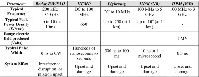
A comparison of the different parameters associated with HPM and other sources is provided in Figure 9.
Parameter Radar/EW/EMI HEMP Lightning HPM (NB) HPM (WB)
Typical Frequency - 35 GHz 200 kHz DC to 100 MHz DC to 10 MHz 100 MHz to 5 GHz 100 MHz to 3 GHz Typical Peak Power Density (W/cm2) Up to 10 (at 10m) 650 Up to 750 (at 1 km) Up to 10 4 (at 1 km) - Range-electric field produced (Volts) - - - - 1 MV Typical Pulse
Width 10 ns to CW nanoseconds to Hundreds of
seconds
500 ns to 100 ms
10 ns to 1
microsecond 0.3 ns
System Effect Interference, disruption, or mission upset
Upset and
damage Upset and damage Upset and damage Upset and damage
Figure 9 - Comparison between Radar/EW/EMI, Lightning, HEMP, NB HPM, and WB HPM (Source: Defense Technical Information Center)
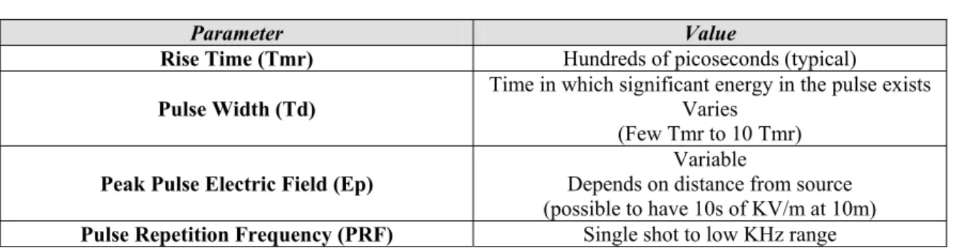
A wide-band HPM device operates at frequencies that can couple with electronic systems. The signal power is distributed among a specified range of frequencies and as such is relatively low at any given frequency. An example of a wide-band HPM signal and characteristics is provided in Figure 10.
T = 1 / PRF
Ep
Tmr
Parameter Value
Rise Time (Tmr) Hundreds of picoseconds (typical)
Pulse Width (Td) Time in which significant energy in the pulse exists Varies (Few Tmr to 10 Tmr)
Peak Pulse Electric Field (Ep) Depends on distance from source Variable
(possible to have 10s of KV/m at 10m)
Pulse Repetition Frequency (PRF) Single shot to low KHz range
Figure 10 - Parameters of a Wideband HPM Pulse
(Source: Defense Technical Information Center)
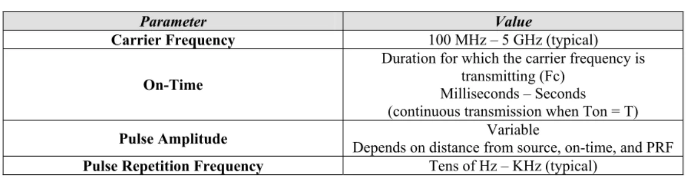
A Narrowband HPM device produces a pulse of energy on a narrow frequency band. The ability to operate high-power emanation is substantial and dependent on the available power source of the device. For this reason, narrowband HPM requires pulsed transmission techniques. The available power to the device determines the energy
emitted and the pulse repetition rate of the device. Narrowband HPM devices are capable of producing over 1 GW of output power in the form of short bursts. An example of a narrowband HPM signal and characteristics is provided in Figure 11.
T = 1 / PRF
Fc
Ton
Parameter Value
Carrier Frequency 100 MHz – 5 GHz (typical)
On-Time
Duration for which the carrier frequency is transmitting (Fc)
Milliseconds – Seconds
(continuous transmission when Ton = T)
Pulse Amplitude Depends on distance from source, on-time, and PRF Variable
Pulse Repetition Frequency Tens of Hz – KHz (typical)
Figure 11 - Parameters of a Narrowband HPM Pulse
(Source: Defense Technical Information Center)
Directed Energy Protection Issues
The protection of electronic and communication systems from DE device emanations primarily requires that electronic systems be protected from these signals entering or coupling with components through direct paths (i.e. antenna) and indirect paths (i.e. other electromagnetic propagation paths).
Shielding techniques provide a significant level of protection from interference from unintentional and intentional sources. In addition, RF hardening techniques applied to electronic components offer an increased protection against emanations from DE devices, whereas they protect the system against emanations if they are able to penetrate shielding or are introduced through other indirect paths.
Additional protective technologies include electromagnetic coupling and RF limiting. The effectiveness of these and other protective technologies can only be determine through susceptibility assessments and may only provide protective measures for the system against emanations in a certain frequency range, power, and duration.
RF Directed Energy Interference: Effects on the Global
Positioning System (GPS)
Overview of the GPS System
The Global Positioning System (GPS) is a satellite-based global navigation system used for both civilian and military applications. The system utilizes the signals sent from GPS satellites to determine the latitude, longitude, and the altitude of the GPS receiver. The effectiveness of these is dependent on the number of satellites in view of the GPS receiver and the relative figure of merit of the signals received from each of the satellites.
The determination of the GPS receiver’s position is calculated using the
difference between precise timing signals transmitted by the GPS satellites to determine the distance from each satellite. The GPS satellites employ highly-accurate clocks to ensure the accuracy of the timing signal, which is basis for distance and position calculations. The onboard processor of a GPS receiver is able to calculate a three
dimensional solution (given that a sufficient number of GPS satellites are in view with an adequate signal figure of merit). A GPS receiver requires three satellites to determine its horizontal (2D) position, and a fourth satellite to determine its altitude (3D).
The signals from the GPS satellites travel nearly 300,000 kilometers toward the earth’s surface through the atmosphere. There propagation of these signals through the tropospheric and ionospheric layers of the earth’s atmosphere has frequency related effects on these signals. In order to minimize these effects, the GPS system uses a dual-frequency design that allows GPS receivers to compensate for these effects. These frequencies are designated as L1 (1575.42 MHz) and L2 (1227.60 MHz).
The GPS signals are transmitted using a spread spectrum technique, which allows multiple satellites to transmit on the same frequencies without interfering with each other and provides a high-level of resistance to noise and interference.
The signals broadcast by GPS satellites are extremely low power, which makes them vulnerable to interference. There are plans to provide an additional frequency to augment the single channel currently available to civilian GPS users.
The GPS system provides two levels of availability known as the Standard
Positioning Service (SPS) and the Precise Positioning Service (PPS). The SPS contains a coarse acquisition (C/A) code transmitted on frequency L1, is available to all GPS
receivers, and provides a horizontal positioning accuracy of one-hundred meters, a vertical positioning accuracy of one-hundred fifty-six meters, and a timing accuracy within 340 nanoseconds. The PPS, a highly accurate positioning mode, contains a P(Y) code which is transmitted on frequencies L1 and L2 and is available to authorized military and government receivers, and provides a horizontal positioning accuracy of twenty-two meters, a vertical positioning accuracy of twenty-seven point seven meters, and a timing accuracy within 200 nanoseconds.
Applications of the GPS System
The GPS system was designed and is operated by the U.S. Department of Defense. The primary application of the GPS system is for military purposes. The GPS system is available for general civilian user around the world. The military and other government agencies can use the GPS system to provide highly accurate positioning information for
location and targeting purposes. The primary civilian applications for GPS include maritime and aviation.
There is a growing awareness of the limitations and vulnerabilities of the GPS signals, system provider and user equipment. These limitations not only affect the accuracy of the system, but also its reliability, integrity and availability.
The increasing reliance on GPS for military positioning, weapons and targeting systems, and civilian aviation and maritime applications is causing an increasing concern relating to the limitations and vulnerabilities of GPS broadcast signals and their affects on the GPS user equipment. A significant vulnerability relates to unintentional and
intentional signal disruptions.
These limitations can affect the reliability, integrity, availability, and accuracy of the entire system. There are modifications to the GPS system to help overcome some of the vulnerabilities of the system components, but until these changes can be
implemented, the vulnerabilities although known represent a significant vulnerability to the system. The vulnerabilities include interference from unintentional as well as intentional sources.
Vulnerability to Disruption
The primary source of unintentional interference of GPS signals, include ionospheric interference and radio frequency (RF) interference from the likes of broadcast television, VHF transmitters, personal electronic devices, Mobile Satellite Service (MSS) communications systems, and ultra-wideband (UWB) radar and com systems.
There are also intentional disruptions to both the satellite and ground station segments of the GPS system using such techniques as signal jamming and spoofing. It is possible to construct an inexpensive one-watt transmitter that is capable of disrupting GPS signals within a relatively small reception area. There are jamming transmitters that are currently available from Russian manufacturers. These devices emanate the jamming signal with an output power of 4 watts, which is capable of disrupting GPS signal
reception for an area approximately 100 nautical miles (radius). There are also low power airborne transmitters that with an output power level of one watt are capable of disrupting GPS signals within a range of 85 km and more powerful airborne transmitters that are capable of GPS signal disruption up to 1000 km.
Summary
The information in this research paper presented information pertaining to the unintentional and intentional disruption of electronic and communication systems by electromagnetic interference. It demonstrates the importance of accounting for noise and interference environments during wireless link design. It also raises the awareness of the possibility of disruption from intentional sources of interference, accounting for this in design parameters, and possible protection measures against this type of interference.
As the reliance on wireless data networks and transmission systems increases to include more critical systems, unintentional and intentional interference have the ability to disrupt these systems and cause temporary or permanent failures, which have the ability to cause catastrophic results due to the unavailability of these wireless data links and the information which they carry.
The most effective protection against these types of disruptions is to conduct susceptibility assessments and provide measures of protection against known interference sources at the data link design phase and attempt to protect against currently unknown or unanticipated interference sources using measures employed after system deployment.
References
Carr, Joseph J., (2001). Practical Antenna Handbook (Fourth Edition), McGraw-Hill, New York, NY.
American Radio Relay League (2000). The ARRL Handbook For Radio Amateurs 2001. American Radio Relay League. Newington, CT.
United States Army. (1998). 1998 ASTMP Annex E Global Technology Capabilities & Trends. Available at http://www.arl.army.mil/tto/ARLITT/ASTMP/aannexe.htm
Schlesinger, Robert, J. (1961). Principles of Electronic Warfare. Prentice-Hall. Englewood Cliffs, New Jersey.
United States Naval Observatory Time Service Department. NAVSTAR GPS Operations. Available at http://tycho.usno.navy.mil/gpsinfo.html
Air Force Association. (2002). Attack at the Speed of Light. Air Force Magazine-Journal of the Air Force Association. Arlington, Virginia.
Tirpak, John A. (Executive Editor). Volume 85, Number 12
Henderson, Mark W., Schriner, David A. (1998). Radio Frequency Weapons – 21st Century Threat Live Fire Testing of Radio Frequency Weapons. United States Navy Pacific Ranges and Facilities.
United States Naval Air Warfare Center Weapons Center. (1999) Directed Energy Weapons – Acronyms & Glossary. Available at
www.nawcwpns.navy.mil/~teclib/dewglossary.html
GeoInformatics Magazine. GPS Limitations and Vulnerabilities, Volume 5, April 2002. Available at http://www.geoinformatics.com/issueonline/issues/2002/april_2002/
pdf_april/22_23_article.pdf
United States Naval Air Warfare Center. "Glossary: Jamming". Electronic Warfare and Radar Systems Engineering Handbook. Obtained online at https://ewhdbks.mugu.navy.
mil/Glossary.htm.
United States Air Force. (2001). Electrical Power and Thermal Management for Airborne Directed Energy Weapons. Available at
Fulghum, David A. (2002). U.S. Funds British Energy Weapon Tests. Aviation Week & Space Technology: September 16, 2002. McGraw-Hill Companies. Obtained at
http://www.aviationnow.com/avnow/search/autosuggest.jsp?docid=130672&url=http%3A%2F%2 Fwww.aviationnow.com%2Fcontent%2Fpublication%2Fawst%2F20020916%2Favi_news.htm.
United States Marine Corps. "Communications security and electronic warfare". U.S.M.C. The Basic School website. Obtained online at