A Distributed Execution Environment
for Large{Scale Workow Management Systems
with Subnets and Server Migration
Thomas Bauer, Peter Dadam
Dept. of Databases and Information Systems
University of Ulm
f
bauer, dadam
g@informatik.uni-ulm.de
Abstract
If the number of users within a workow management system (WFMS) increases, a central workow server (WF{server) and a single local area network (LAN) may become overloaded. The approach describes an execution environment which is able to manage a growing number of users by adding new servers and subnets. The basic idea is to decompose processes into parts which are controlled by dierent WF{servers. That is, during execution of a workow instance its execution (step) control may migrate from one WF{server to another. By select-ing the appropriate physical servers (for hostselect-ing the WF{servers) in the appropriate LANs, communication costs and individual WF{server workload can be reduced signicantly.
1 Introduction
Since a couple of years there is a growing interest in using WFMS for implementing process{ oriented application systems. As the benet of such application systems increases with the number of applications being serviced, the number of workow applications and WFMS users within a company will signicantly grow year by year once it has started to go that way. Thus, the question arises how to manage large numbers of users (may be even tens of thousands KAGM96]) and high volume data transfer (e.g. in conjunction with multi{media applica-tions) within a WFMS.
Most existing systems use a central WF{server. It is easy to see that it becomes a bottleneck and will be overloaded under a high load. To reduce the load of the WF{server it can be replicated. This method can be used in combination with our approach (section 3.3) and is used in AKA+94] (see section 5), for example. But there remains a bottleneck, namely the
band{width of the subnet of the WF{server.
To see that a LAN really may become a bottleneck, let us perform a little numerical exercise. Let us assume that 300 users are working concurrently, each of them needing 5 minutes (= 300
seconds) in the average to perform one (workow) step. This means, that in the average one step is executed per second. Let us further assume, that in the average 10% of all users have the appropriate role to execute a certain step. That is, this step should appear in the worklist of these users. Assuming a packet size of 100 byte, we will need approx. 4 packets for transmitting the worklist entries and respective acknowledgements, in total 30 4 100 byte = 12 KB per second. If we further assume that the selection and execution of one step requires the transmission of 300 KB of input data and produces the same amout as output, then 12 KB + 600 KB = 612 KB = 4.9 megabits of pure data per second have to be transferred in the average. Taking all the additional overhead into account this would already lead to an overload for a simple Ethernet{based LAN. In general, due to the potentially large number of individual messages, even very expensive high{speed LANs may become overloaded for a larger number of users.
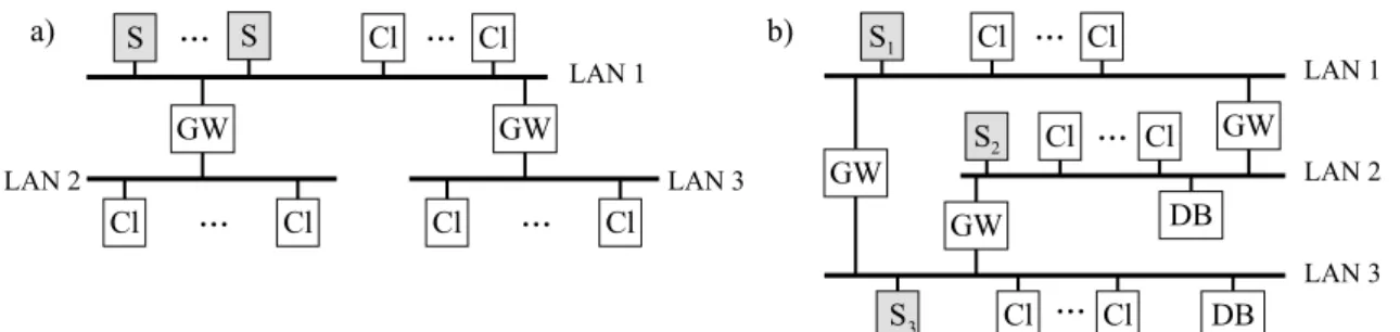
Our approach to solve this problem is to distribute the load by using several subnets. Not every decomposition of a single LAN into subnets leads to the desired result, however. In gure 1a, for example, three subnets are used. Because all WF{servers are in LAN 1, this subnet is burdened with the full communication load. The existence of the other subnets (LAN 2 and LAN 3) does not lead to any load reduction for LAN 1. The same problem appears, if we assume that in gure 1b WF{server S1 has all of its clients in subnet LAN 3
and WF-server S3 has all its clients in subnet LAN 1. In this case both, LAN 1 and LAN 3
have to take the full communication load as if they were in a single LAN. On the other hand, if in the scenario illustrated in gure 1b WF{server S1 has all its clients in LAN 1, S2 in
LAN 2, and S3in LAN 3, then all communication can take place locally within the individual
subnet. In this case we achieve a signicant decrease in communication load per subnet.
S1 Cl Cl S2 Cl Cl ... GW ... GW GW DB S Cl ... Cl DB S S Cl Cl Cl Cl ... GW ... ... a) b) Cl Cl GW ... LAN 1 LAN 1 LAN 2 LAN 3 LAN 3 LAN 2 3
Figure 1 Structure of networks (S: WF{server, Cl: client, GW: gateway (router), DB: database,
external data source).
These examples show that the introduction of subnets can help to reduce the communication load per subnet, but it also shows that the WF{servers and clients must be in the \right" subnet to achieve the desired load reduction. As we will see later, it will not be sucient to consider workows as a whole (each of it being controlled by a single WF{server), but that we have even to split workows into parts each of it being controlled by another WF{server to nd satisfying solutions. The development of criteria for \good" and \bad" distributions, for splitting workows into parts, as well as the presentation of a corresponding design method
for WF networks are the main issues of this paper.
The remainder of the paper is organized as follows: In section 2 the optimization problem and in section 3 the problem solution are described. Section 4 analyzes the eciency of our approach, especially the creation of subnets and decomposition of workows. Section 5 discusses related approaches and section 6 concludes with a summary and an outlook.
2 Problem Description
The optimization problem can be sketched as follows: Given a set of processes consisting of several steps, nd a distribution of processes to WF{servers such that the communication load in the subnets is minimized under the restriction that no subnet, WF{server, and gateway is overloaded. Until further notice we assume that the users (clients) can be distributed to the subnets in any way. Restrictions are discussed in section 3.2.2.
The communication costs for each WF{step are caused by:
step oering (
SO
k)1: the transmission of the information about the step to all users
resp. clients with an appropriate role and their acknowledgement,
step selection (
SS
k): the transmission of the information to the server that a certainuser has selected the step and the transmission of the the input parameters for this step to the corresponding client,
worklist refresh (
WR
k): sending a delete-message for that step to the other clients tobring their worklists up{to{date and transmitting their acknowledgements,
result transfer (
RT
k): the transmission of the output parameters of an activity to theserver and transmitting its acknowledgement.
migration costs (
MI
m): transmitting (transfering) workow control information fromone server to another (see section 4.2 for details)
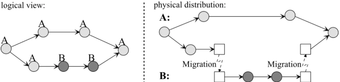
In our approach, the unit of distribution are not complete processes but single steps. This makes sense, because the sum of the communication costs is smallest if all steps are allocated at the optimal WF{server (and not only the process as a whole). Therefore it may become necessary to decompose a process into parts which are managed by dierent WF{servers as illustrated in gure 2. That is, during execution a process (resp. its control) may migrate from one WF{server to another. If this happens, all data of this process instance is copied to the subsequent WF{server and deleted at the previous one (see section 4.2 for further details). For estimating the load of each component we make two simplifying assumptions at the moment2. Firstly, the executions of steps takes place equally distributed during time period
T
. Secondly, each user with an appropriate role has the same probability (independent of its subnet) for selecting a step. Concerning the WF{model itself, we do not make any restricting assumptions. That is, the model may contain AND{branches, OR{branches, iterations etc.1
SOk are the costs for maintaining the worklist of one user for step k. 2For a more sophisticated model see section 3.1.
A A A B B A A A: B:
logical view: physical distribution:
Migration Migration
Figure 2 The steps of the process are assigned with the WF{servers A and B. The system decomposes
the process in a part for WF{server A and one for WF{server B. At the points the control changes between the servers, migration steps are inserted.
We only assume resp. require, that
E
k, the number of executions of stepk
during a time periodT
, can be estimated (e.g. based on statistical information).Let
u
k denote the number of appropriate users for stepk
. Thus the step appears inu
k worklists. Once one user has decided to execute the step, it has to be removed fromu
k;1worklists3. We now consider the average communication load resulting from the execution of
step
k
. At rst we look at the loadC
kSk in the subnet where the WF{server (S
k) resides:C
kSk =E
T u
k kSO
k+SS
k+ (u
k ;1)WR
k+RT
k(F1)
The load in the other subnets can be estimated as follows. In total we have
u
k users which qualify to execute stepk
. Ifu
xk of these users (clients) belong to another subnetx
(which does not containS
k), the probability of stepk
to be executed in subnetx
is uuxkk. If the step is executed in subnetx
, the parameters have to be transmitted to that client (SS
k+RT
k), but there is no need to refresh its worklist (;WR
k). Thus the communication load for stepk
insubnet
x
can be approximated as follows:C
xk =E
T u
k xk (SO
k+WR
k) +u
u
xkk (
SS
k+RT
k;WR
k)(F2)
The total load which a process
P
creates in subnetN
is the sum of the step execution load and the migration load for the migration stepsm
.MI
Nm species the migration costs for stepm
. They are zero, if the subnetN
is not aected by this migration. Thus we get:C
NP =Pk
C
Nk+P
m
E
T MI
m Nm (F3)The total load of a subnet
N
isC
N =PP
C
NP. (F4)The load of the WF{servers and gateways is calculated in a similar way.
3The item can be removed from the worklist of the user that has selected this step without further
3 Derivation of Appropriate Network Topologies and
Work-ow Designs
3.1 Basic Idea
To minimize communication costs, the control of each step should be allocated in the subnet with the highest probability for executing this step. By doing so, the probability that all communication remains inside this subnet becomes very high. The probability for a certain step to be executed in a certain subnet can be approximated using the distribution of the users.
We introduce a weight
g
xi (0g
xi1) for each useri
and subnetx
which corresponds to theprobability that this user chooses a step. The weight is used to describe the relative amount of time the user spends in working with the WFMS in this subnet. It is usually 1, but can be smaller if the users has only a part time job or if the user works in several subnets, for example.
The weights are used for calculating the probability that a step is executed in a certain subnet. In a WFMS only users owning one of the roles of a certain step are allowed to execute this step and the step appeares only in their worklists. In our model the subnet of each user is known. With this information it is possible to calculate for each step how many \full" users exist in each subnet by computing the sum of the weights of the appropriate users for step
k
:u
xk=Pi
g
xi.3.2 Design of Processes
So far we have explained the problem and the characteristics of good solutions. In this section we show how such good distributions can be achieved. The problem can be solved by using a closed mathematical optimization approach, similar to some of the solutions proposed in distributed database for nding an optimal distribution of fragment relations ML77, OV91, Dad96]. Taking this approach, one can nd a optimal solution, in principle. The WF designer, however, has to speciy a lot of (rather uncertain) parameter and constraint values which makes this approach rather expensive and thus unattractive. (And the practical value of the computed result is questionable, too.)
We, therefore, are in favour of an interactive and iterative approach. It starts modeling an (initial) distribution of users and WF{servers, and by analyzing the resulting load iteratively and interactively improving the modeling until an acceptable solution is found.
3.2.1 Modeling and Analysis
In our approach, a WF design iterates through the following steps:
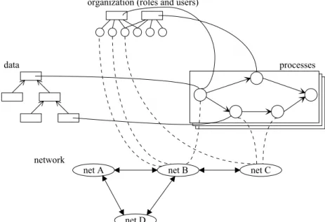
1. The WF designer is modelling the processes like in a central WFMS (describing orga-nization, data, processes cf. upper part of gure 3).
2. The WF design system proposes an initial distribution of users and WF{servers. 3. The WF design system computes the resulting load for each component (subnet, WF{
server, gateway, ...) using the model and additional statistical information.
4. If the load of all component is within the target range, the design is completed and sent to the aected WF{servers.
5. If a component is overloaded the model is modied by the WF designer using the outcome of the user distribution analysis (see \Assigning Users to Subnets") and by computing (assisted by the system) the consequences of decomposing processes (see \Distribution of Step Control"). The design process is continued at step 3.
Note, that this analysis is completely done at build time. That is, it does not disturb running processes. After WF design has been completed, the process execution model is generated, it is decomposed into parts and complemented with migration steps (if a decomposition had been selected by the WF designer), and transmitted to the aected WF{servers.
network
net A net B net C
netD
organization (roles and users)
data processes
Figure 3 Modeling of processes (only partially drawn).
3.2.2 Algorithms
The WF design system proposes (initial) distributions of users and step control. The under-lying analyses and algortihms are explained in the following.
Assigning Users to Subnets
The following algorithm assumes that the processes as well as the users and their roles are known. It computes \clusters" of users who can perform the same (or a similar) collection of steps. These clusters are candidates for building respective subnets. The algorithm implicitly
assumes that one starts from scratch, that is users are not yet assigned to subnets (see \Applicability" for further comments).
The problem is similar to the distribution of attributes at vertical partitioning in distributed database systems. For this reason the following algorithm is adopted from this research area NCWD84, NR89]. First we sketch the algorithm then we explain its meaning and the meaning of the symbols used.
1. create the user step matrix
use
0ki 2. standardize
use
0ki to
use
ki3. compute the user anity matrix
aff
ij usinguse
ki 4. use the known algorithms to nd clusters inaff
ij 5. while (there is a cluster that is too large)decompose that cluster
6. assign the clusters to the subnets (more than one cluster per subnet is allowed) 7. change (manually) the assignment of users to subnets if necessary (and possible) The user step matrix
use
0ki contains the weights of the users (
g
i)4 with respect to their abilityof executing a certain step.
use
0ki =
g
i if useri
can execute stepk
0 otherwisee.g.
use
0 user1 2 3 4 step 1 1 0 0 0.5
2 0 1 1 0 3 0 1 1 0.5 Then this matrix becomes standardized so that it contains the probability that a user will execute a certain step. The divisor of the fraction will be unequal to 0, because8
j
:use
0
kj = 0 would mean that no user is allowed to execute this step.
use
ki =use
0 ki P juse
0 kjuse
user 1 2 3 4 step 1 2/3 0 0 1/3 2 0 1/2 1/2 0 3 0 2/5 2/5 1/5 Now the user anity matrix can be created. It contains the degree of the connection between users. If a cluster of users has high values in this matrix, they have common steps and should be in the same subnet. Such clusters of users can be found with the algoritms described in NCWD84] and (with a better complexity) in NR89].aff
ij =P kuse
kiuse
kjE
k Frequency of stepk
:k
1 2 3E
k 100 60 10aff
1 2 3 4 1 44.44 0 0 22.22 2 0 16.6 16.6 0.8 3 0 16.6 16.6 0.8 4 22.22 0.8 0.8 11.51 In this example one cluster would consist of the users 1 and 4 and another of the users 2 and 3. Each of these clusters could be allocated in one subnet of their own. The algorithmdoes not take into account the \quality" of the clusters. That is, clusters may be suggested which are too large and thus would lead to a high load in the respective subnet. In such cases clusters have to be decomposed manually into appropriate parts (subnets) to achieve the desired result. If there are more clusters than subnets, several small clusters must be assigned to one subnet, and if the physical location of a user prevents him from being in the proposed cluster, it has to be assigned to another cluster.
Applicability
This simple algorithm presented here, assumes that the WF design is starting from scratch, that is users are not yet assigned to subnets. But even if it is used in an existing WFMS envi-ronment where users are already assigned to subnets, the results can give valuable suggestions for improvements concerning the choice of WF servers and the decomposition of processes.
Distribution of the Step Control
As already mentioned above, workows are assigned to WF{servers at the granularity of single steps instead of complete workows. The calculation of the optimal distribution of the step control would have exponential complexity, because every step can be controlled by each WF{server. Our greedy algorithm discussed below will not always nd the optimal solution, but it will deliver a good result for the common cases and has polynomal complexity.
The idea is to select at rst the optimal subnet for every step without considering the mi-gration costs. Then for each single step in a subnet it is checked if it is cheaper to save the migration costs (
MI
m) and to assign the step to the WF{server of the step before or after the current one, with higher costs for step execution (SS
k,RT
k) and worklist maintenance (SO
k,WR
k). This is also done for all groups of 2, 3,... steps controlled by one and the same WF{server. The algorithm can be sketched as follows:for each step: assign the WF{server of the subnet with the most appropriate users for i = 1, 2, ...
for each group with i steps in one subnet:
check if it is cheaper to control the step by the WF{server before or after the current one if yes: assign the step(s) to that WF{server
3.3 Renements
Our method achieves scalability by distributing the steps of the processes among the WF{ servers. If there is only one relevant process with only one step, however it is not possible to distribute anything, because one step can only be controlled by one WF{server. Even though this is not a typical scenario for a WFMS, there are several solutions (besides using future hardware and/or futur networks):
One solution consists of splitting the process into several processes. If a process has to serve customers, one could e.g. assign the customers with names A ...M to process
P
1 and N ...ZAnother solution is to extend our approach with WF{server replication. Instead of one WF{ server for each step, several are used in dierent subnets. Only one of them can be in the optimal subnet, however, the others have to be in less suitable subnets. But even in this case the load can be reduced (see section 4.1), if it is distributed equally among the WF{servers. This is possible e.g. by randomly choosing one of these servers for starting or migrating the processes.
The external data sources shown in gure 1 are a performance{critical aspect, too. They also can become a bottleneck. Therefore they have to be taken into account during the analysis. For this purpose the amount of communication with them has to be estimated for each step. It can be reasonable (where applicable), to use several (independent) databases in order to keep communication local to a subnet as often as possible.
4 Eciency Analysis
In the subsequent two sections we will analyze the communication costs in dierent scenarios. At rst we consider the case that processes are not decomposed, i.e. no process migration takes place. This means that, all steps of a process are controlled by one and the same WF{server. Subsequently we will analyze scenarios with process migration.
4.1 Using Multiple Servers without Process Migration
In the following, we analyze the communication trac in the subnets which is caused by the maintenance of worklists (
SO
k,WR
k) and the transfer of parameter data (SS
k,RT
k). We assume that the processes do not migrate (i.e. they are controlled by one WF{server from their beginning until their termination) which approximates also the case that migration costs are small compared with the step execution costs.In the sequel, we analyse three interesting cases. Some related cases are mentioned, others can be easily derived in the same way.
Case 1:
All clients are located in the subnet of the corresponding WF{server.Case 2:
The majority of the clients is located in the \right" subnet.Case 3:
The majority of the clients is located in the \wrong" subnet.For each of these cases we compare two scenarios. In the rst scenario we have only one subnet with one central WF{server. In the other scenario we have two subnets, each with a WF{server, connected by a gateway. This is a scenario5 as described in section 1. For reasons
of simplicity we consider only two subnets, but the results would be the same for any number of subnets.
To simplify our analysis we ignore the weights for a moment and assume that every client having the appropriate role has the same probability for executing the step. Since the data exchanged with each client has the same volume (because
SO
k,SS
k,WR
k,RT
k are equal forall users), there is no need for counting messages or data packets. To compare the load in the dierent subnets, it is sucient to count how many clients are involved in the execution of how many steps for a given set of processes. Figure 4-1a illustrates the case where two processes, each involving two clients (discriminated by solid and dotted lines), are executed by one server. In this case we count 4 \connections" in this subnet in total. Opposed to that, two servers, each executing one process, are used in gure 4-1b. In this case we have only 2 \connections" in each subnet.
To simplify the comparison, we assume that the total number of processes to be served is equally distributed among the servers. This leads to equal loads for all WF{servers and subnets and it becomes possible to compare the subnet load in the two scenarios.
Case 1:
Each client is located in the same subnet as the WF{server of the corresponding steps. In this case the gateway need not to be used and { as each WF{server serves 50% of the processes { the communication in each subnet is halved. This is the best case because all communication is completely taking place inside the subnets. Figure 4-1a shows that in the scenario with one LAN there are 4 connections between WF{server and clients, while in gure 4-1b there are only 2 connections per subnet. If there would be n subnets instead of two, the load would be 1nth of the not distributed case.
Case 2:
Here the majority, but not all clients are in the \right" subnet. It is evident that this also leads to an improvement compared to having only one net (see gure 4-2). There are 2 clients in the subnet of the WF{server and 1 in the other one. This leads to 4 connections instead of 6.If there would be as many clients in the subnet of the WF{server as in the other one, we would save 25% of the communication. One can demonstrate this in gure 4-2 by deleting the connection to Cl1 and Cl3. In this case, there remain 4 (2a) resp. 3 (2b) connections.
The saving of 25% is achieved because in the case of a communication with a client in the own subnet (50% of the cases) the other subnet (50% of the subnets) is not used.
Case 3:
Here most of the clients are located in the \wrong" subnet. Even in this case we save communication as demonstrated in gure 4-3. In this example only 1 client is in the subnet of the WF{server but 2 clients are in the other one. Even in this unfavorable scenario only 5 connections are needed instead of 6. The saving exists as long as there are clients in the subnet of the WF{server, because for communication with these clients the other subnet is not used.The worst case is, if all clients are in the \wrong" subnet. Even in this case, however, the subnet load is not higher than in the single net version. All subnets are used for all communications, but this case should never occur in practice. One always could distribute the processes in another way, so that at least for some steps there is a user in the \right" subnet. For more than two subnets in a completely intermeshed network there are always subnets with a reduced load. Even if all clients are in \wrong" subnets there are always subnets which are not involved in communication for certain steps because there is no through trac. Therefore our approach is also eligible for unfavorable distributions of users.
S1 Cl1 GW Cl2 S2 Cl3 Cl4 S Cl1 Cl2 Cl3 Cl4 S1 Cl1 GW Cl2 S2 Cl3 Cl4 S Cl1 Cl2 Cl3 Cl4 S1 Cl1 GW Cl2 S2 Cl3 Cl4 S Cl1 Cl2 Cl3 Cl4 1a) 2a) 3a) 1b) 2b) 3b)
Figure 4 Comparison of scenarios with one and two subnets for dierent communication patterns.
To achieve the best eciency the users and the control of steps must be distributed in such a way that as many users as possible are in the same subnet as the WF{server that controls their steps.
4.2 Using Multiple Servers with Process Migration
In this section we consider the case that { due to the distribution of users { no single WF{ server does really optimally t for controlling a given process. In such cases it may be better to decompose the process into parts such that each of it can be controlled by the optimal WF{server. That is, we consider the case that after execution of a set
S
1 of steps in subnetN
1, the process control is migrated to another WF{server in subnetN
2 which controls theexecution of the remaining set
S
2 of steps. The crucial question is whether the reduction incommunication load due to the migration is counterbalancing the migration costs. We can discriminate three cases:
ideal case
mixed positive case negative case
Ideal case:
In this case, after migration all clients are in the same subnet (N
2) as the newWF{server. Thus, after migration, subnet
N
1 has no communication load for the remainingresulting from the migration (
C
MI = ETmMI
) { which we have to count two times because it occurs in both the \sender" and the \receiver" subnet { and using formula (F2) we can compute, how many remaining steps (!S
2) are needed to make a migration rewarding. This
is the case, if the following unequation is satised: 2
C
MI<
P k2S 2C
N1 k where P k2S 2C
N1k describes the savings in subnet
N
1, if the control for the stepsS
2 = fs
2 1
:::s
2n
g is migrated to the WF{server in the other subnet.
Mixed positive case:
In this case, after migration most { but not all { clients related to the remaining steps (!S
2) are in the \right" subnet (
u
N1
k
< u
N2k ). This means that we achieve some saving in subnet
N
1 because some of the communication load is now completelyhandled in subnet
N
2. In subnetN
2, however, the load is higher than without migration,because this subnet is now also burdened with the communication with the clients in subnet
N
1. The decision problem can be formulated as follows: The migration is rewarding if thefollowing unequation holds: 2
C
MI<
P k2S 2 (C
kSk;C
N1 k ) | {z } savings inN
1 ; (C
Sk k ;C
N2 k ) | {z } additional load inN
2 , 2C
MI<
P k2S 2 (C
N2 k ;C
N1 k ) | {z } () (F5) As we consider here the case thatu
N1k
< u
N2k , expression () will always be positive. That
means, having enough steps in
S
2, migration is rewarding.Negative case:
In this case, after migration most clients are in the \wrong" subnet (u
N1k
u
N2k ). The analysis is the same like in the previous case and thus also leads to the same unequation (F5). In this case, however, expression () can never become positive and thus
migration is never rewarding (as expected).
The circumstances under which migration is rewarding are demonstrated in the following numerical example: We assume equal steps in
S
2 with the same frequency for each step (E
k)and for the migration step (
E
m). They shall have the following characteristics: input parameter volume:IN
k = 300 KBoutput parameter volume:
OUT
k = 100 KB total process instance data:INST
= 1000 KB data transmitted for a worklist entry:WL
= 0:
1 KBdata transmitted for an acknowledgement:
Ack
= 0:
1 KB (minimal packet size) appropriate users in subnetN
1:u
N1
k = 10
appropriate users in subnet
N
2:u
N2
k = 200, altogether
u
k = 210With this information values for the variables in the formulas in section 2 can be calculated as follows:
SO
k =WL
+Ack
= 0:
2 KBSS
k =WL
+IN
k = 300:
1 KBWR
k =WL
+Ack
= 0:
2 KBRT
k =OUT
k+Ack
= 100:
1 KBMI
=INST
+Ack
= 1000:
1 KBNow (F1) can be used to calculate the load in the subnet in which the WF{server is located:
C
kSk =E
T
k (210 0:
2 + 300:
1 + 209 0:
2 + 100:
1) KB =E
T
k 484 KBIf the WF{server is located in
N
2 the resulting load in subnetN
1 can be calculated with (F2):C
N1k =
E
T
k 23 KBIf the WF{server is located in the \wrong" subnet
N
1, the load inN
2 is much higher:C
N2k =
E
T
k 461 KBUsing formula (F5) we can calculate that the migration is rewarding if
E
T
m 2 1000:
1 KB<
P k2S 2E
T
k (461;23) KB WithE
k =E
m follows (jS
2jis the number of steps in
S
2):2000
:
2<
jS
2j 438
Therefore the migration is rewarding if there are at least 5 steps in
S
2.5 Related Work
The approach described in this paper concentrates on the reduction of communication load in large{scale WFMS environments. To achieve this goal, we use subnets as well as the de-composition and distributed control (via process migration) of processes. For this type of application scenario we are only interested in process{oriented systems (as opposed to e.g. Lotus Notes), because in large scale environments the corresponding functionality is needed. Most process{oriented systems use a central WF{server and are therefore not (directly) suit-able for our target environment. In the following we discuss some distributed approaches. FlowMark IBM95] is a system with a central WF{server, but it is possible to execute a \subprocess" in another FlowMark system (domain). If process control shall be distributed, the concept of subprocesses has to be used, because subprocesses can be executed at remote servers. The logic is comparable to a remote procedure call. That is control returns to the caller after completion of the subprocess.
Exotica AKA+94] uses so called \clusters" to achieve parallelism. A cluster consists of one
WF{database and replicated WF{servers. The user has to connect with one WF{server of each cluster. By replication, load reduction is achieved for the WF{servers within a cluster. The control of a process instance stays in the cluster in which the process was started. By selecting an appropriate cluster, load balancing among the clusters can be achieved, but it may cause long distance communications to the users.
In MOBILE HS96] server replication is used, too. The WF{model is separated into several perspectives (organization structure, control ow, etc.) each with its own database and its own
server. If one of these servers is overloaded it becomes replicated. Static data of these servers are replicated, dynamic are partitioned and assigned to only one server. Scalability is achieved under the assumption that there exist independent partitions (e.g. for dierent departments). Both approaches (Exotica and MOBILE) do not consider subnet load. Therefore, process instance migration is not used.
There are several approaches which do not use WF{servers at all. They have in common, that after nishing a step the process instance migrates directly to the node of the following step. Usually a reliable communication system is used for this purpose. The disadvantage is that the role resolution is only done at the rst time when a step becomes available AGK+95].
As consequence, this step is not oered to users which are connecting at a later point in time. At INCAS BMR94] every step is dedicated to exactly one user. Thus, there is no need for synchronization, but the functionality is very limited. A similar approach is persued in the Mentor project WWWK96a, WWWK96b], where each step is assigned with exactly one \entity" and there is also no role resolution. Opposed to this, in Exotica/FMQS AMG+95]
a step is oered to all users with an appropriate role. Because there exists no WF{server for coordinating the step selection, a distributed (and therefore expensive) synchronization mechanism has to be applied. But the problem remains, that a step is not oered to users which connect to the WFMS after this step is ready for selection. All these approaches have in common that at every step the whole process instance migrates.
6 Summary
In this paper we have concentrated on the aspects of how to optimize the communication load in WFMS environments with a large number of users. We have shown that with the usage of subnets and by assigning WF{control to the \right" WF{servers, the load can be distributed and thus more users can be served. We have described how { based on easily to obtain information { one can develop algorithms for calculating such distributions.
We have further shown that it can be favourable not always to treat and control workows as a whole but to decompose them into parts which are controlled by dierent WF{servers. We have analyzed under which circumstances such a \process migration" is rewarding. There are further possible improvements of our approach, e.g. dynamic optimization of the step control distribution at runtime. Furthermore several aspects as the dynamic modication of processes at runtime (exeptions) or process abortion with compensation of already executed steps have to be integrated in our approach. This will be subject of our future work.
References
AGK+95] G. Alonso, R. Gunthor, M. Kamath, D. Agrawal, A. El Abbadi, and C. Mohan.
Exotica/FMDC: Handling Disconnected Clients in a Workow Management System. In Proc. of the Third Int. Conference on Cooperative Information Systems, pages 99{110, Vienna, May 1995.
AKA+94] G. Alonso, M. Kamath, D. Agrawal, A. El Abbadi, R. Gunthor, and C. Mohan.
Failure Handling in Large Scale Workow Management Systems. Technical Report RJ9913, IBM Almaden Research Center, November 1994.
AMG+95] G. Alonso, C. Mohan, R. Gunthor, D. Agrawal, A. El Abbadi, and M.
Ka-math. Exotica/FMQM: A Persistent Message{Based Architecture for Dis-tributed Workow Management. In Proc. of the IFIP Working Conference on Information Systems for Decentralized Organisations, Trondheim, August 1995.
BMR94] D. Barbar!a, S. Mehrotra, and M. Rusinkiewicz. INCAS: A Computational Model for Dynamic Workows in Autonomous Distributed Environments. Technical report, Matsushita Information Technology Laboratory, Princeton, May 1994.
Dad96] P. Dadam. Verteilte Datenbanken und Client/Server{Systeme (Distributed Databases and Client/Server Systems). Springer{Verlag, 1996. (in german). HS96] P. Heinl and H. Schuster. Towards a Highly Scaleable Architecture for
ow Management Systems. In Proc. of the 7th Int. Conference and Work-shop on Database and Expert Systems Applications, DEXA'96, pages 439{444, Zurich, September 1996.
IBM95] IBM. FlowMark { Modeling Workow, Version 2.1, First edition, March 1995. Document Number: SH19-8241-00.
KAGM96] M. Kamath, G. Alonso, R. Gunthor, and C. Mohan. Providing High Avail-ability in Very Large Workow Management Systems. In Proc. of the 5th Int. Conference on Extending Database Technology, pages 427{442, Avignon, March 1996.
ML77] H.L. Morgan and K. D. Levin. Optimal Program and Data Locations in Com-puter Networks. Comm. of the ACM, 20:315{322, 1977.
NCWD84] S. Navathe, S. Ceri, G. Wiederhold, and J. Dou. Vertical Partitioning Al-gorithms for Database Design. ACM Transactions on Database Systems, 9(4):680{710, 1984.
NR89] S. Navathe and M. Ra. Vertical Partitioning for Database Design: A Graphical Algorithm. In Proc. of the 1989 ACM SIGMOD Int. Conference on Manage-ment of Data, volume 18, pages 440{450, Portland, June 1989.
OV91] M.T. Ozsu and P. Valduriez. Principles of Distributed Database Systems. Pren-tice Hall, 1991.
WWWK96a] J. Weissenfels, D. Wodtke, G. Weikum, and A. Kotz{Dittrich. The Men-tor Architecture for Enterprise{wide Workow Management. In Proc. of the NSF Workshop on Workow and Process Automation in Information Systems, pages 69{73, Athens, May 1996.
WWWK96b] D. Wodtke, J. Weissenfels, G. Weikum, and A. Kotz Dittrich. The Mentor Project: Steps Towards Enterprise{Wide Workow Management. In Proc. of the 12th IEEE Int. Conference on Data Engineering, pages 556{565, New Orleans, March 1996.