From Business Process Models to
Process-oriented Software Systems
?Chun Ouyang1, Marlon Dumas1, Wil M.P. van der Aalst2,1 Arthur H.M. ter Hofstede1, and Jan Mendling1
1
Faculty of Information Technology, Queensland University of Technology, GPO Box 2434, Brisbane QLD 4001, Australia
{c.ouyang,m.dumas,a.terhofstede,j.mendling}@qut.edu.au 2
Department of Computer Science, Eindhoven University of Technology, GPO Box 513, NL-5600 MB, The Netherlands
{w.m.p.v.d.aalst}@tue.nl
Abstract. Several methods for enterprise systems analysis rely on flow-oriented representations of business operations, otherwise known as business process models. The Business Process Modeling Notation (BPMN) is a standard for capturing such models. BPMN models facilitate communica-tion between domain experts and analysts and provide input to software development projects. Meanwhile, there is an emergence of methods for enterprise software development that rely on detailed process definitions that are executed by process engines. These process definitions re-fine their counterpart BPMN models by introducing data manipulation, application binding and other implementation details. The de facto standard for defining executable processes is the Busi-ness Process Execution Language (BPEL). Accordingly, a standards-based method for developing process-oriented systems is to start with BPMN models and to translate these models into BPEL definitions for subsequent refinement. However, instrumenting this method is challenging because BPMN models and BPEL definitions are structurally very different. Existing techniques for trans-lating BPMN to BPEL only work for limited classes of BPMN models. This paper proposes a translation technique that does not impose structural restrictions on the source BPMN model. At the same time, the technique emphasizes the generation of readable (block-structured) BPEL code. An empirical evaluation conducted over a large collection of process models shows that the resulting BPEL definitions are largely block-structured. Beyond its direct relevance in the con-text of BPMN and BPEL, the technique presented in this paper addresses issues that arise when translating from graph-oriented to block-structure flow definition languages.
Keywords: Business process modeling, business process execution, BPMN, BPEL
1 Introduction
Business Process Management (BPM) is an established discipline for building, maintaining and evolving large enterprise systems on the basis of business process models [6]. A business process
?
This work is supported by the Australian Research Council under the Discovery Grant “Expressiveness Comparison and Interchange Facilitation between Business Process Execution Languages” (DP0451092).
model is a flow-oriented representation of a set of work practices aimed at achieving a goal, such as processing a customer request or complaint, satisfying a regulatory requirement, etc.
The Business Process Modeling Notation (BPMN) [27] is gaining adoption as a standard notation for capturing business processes [34]. The main purpose of business process models generally, and BPMN models in particular, is to facilitate communication between domain analysts and to support decision-making based on techniques such as cost analysis, scenario analysis and simulation [34, 36]. However, BPMN models are also used as a basis for specifying software system requirements, and in such cases, they are handed over to software developers. In this setting, the motivating question of this paper is: How can developers fully exploit BPMN process models produced by domain analysts?
Meanwhile, theBusiness Process Execution Language (BPEL) [15] is emerging as a de facto standard for implementing business processes on top of Web service technology. More than a dozen platforms, such as Oracle BPEL, IBM WebSphere, and Microsoft BizTalk, support the execution of BPEL process definitions (see http://en.wikipedia.org/wiki/BPEL for a list). BPEL process definitions are more detailed than BPMN ones. For example, they include elements related to data manipulation, Web service bindings and other implementation aspects that are not present in their counterpart BPMN models.
In this setting, a standards-based approach to process-oriented systems development is to take BPMN models as input and to translate these models into templates of BPEL process definitions for subsequent manipulation by software developers. However, the instrumentation of this method is hindered by a fundamental mismatch between BPMN and BPEL [35]. A BPMN model consists of nodes that can be connected through control flow arcs in arbitrary ways. Meanwhile, BPEL offers block-structured constructs to capture control flow, plus a notion of “control link” to connect a collection of activities in an acyclic graph. In other words, BPMN supports arbitrary control-flow structures, whereas BPEL supports only restricted control-flow structures. As a result, existing mappings between BPMN and BPEL [23,27] impose restrictions on the structure of the source models. For example, they are restricted to BPMN models such that every loop has one single entry point and one single exit point and such that each point where the flow of control branches has a corresponding point where the resulting branches merge back.
The ensuing problem is to some extent similar to that of translating unstructured flowcharts into structured ones (or GOTO programs into WHILE programs) [28]. A major difference though is that process modeling languages include constructs for capturing parallel execu-tion and constructs for capturing choices driven by the environment (also called event-driven choices), as opposed to choices driven by data such as those found in flowcharts. It turns out
that due to these additional features, the class of structured process models is strictly contained in the class of unstructured process models as discussed in [18]. This raises the question:
Can every BPMN model be translated into a BPEL model?
This paper shows that the answer is yes. However, the resulting translation heavily uses a construct in BPEL known as “event handler” which serves to encode event-action rules. Specif-ically, the original BPMN process model is decomposed into a collection of event-action rules that trigger one another to encode the underlying control flow logic. Arguably, the resulting BPEL code is not readable and thus difficult to modify and to maintain. For the generated BPEL code to be readable, the control flow logic should be captured using BPEL’s block-structured control flow constructs and control links, as opposed to a construct intended for event handling. But since BPEL’s control flow constructs are syntactically restricted, it is not always possible to generate BPEL code satisfying these readability criterion. Therefore, the paper also addresses the question:
Are there classes of BPMN models that can be translated into “readable” BPEL process definitions, i.e. process definitions in which control flow dependencies in the source model are not encoded as event handlers?
This paper identifies two such classes of BPMN models. The first one corresponds to the class of structured process models as defined in [18]. Such models can be mapped onto the structured control flow constructs of BPEL. The second class corresponds to the class of syn-chronising process models as defined in [17], which can be mapped onto BPEL control links. An acyclic BPMN model, or an acyclic fragment of a BPMN model, falls under this class if it satisfies a number of semantic conditions such as absence of deadlock. We apply Petri net analysis techniques to statically check these semantic conditions on the source BPMN model.
The paper also shows how the proposed translation techniques can be combined, such that a technique yielding less readable code is only applied when the other techniques can not, and only for model fragments of minimal size. The combined translation technique has been implemented as an open-source tool, namely BPMN2BPEL.
It is beyond the scope of this paper to discuss every detail of a translation from BPMN to BPEL. Many of these details, such as how to map tasks and events into BPEL, are discussed in an appendix of the BPMN standard specification [27]. Instead, this paper concentrates on open issues arising from the mismatch between BPMN and BPEL discussed above.
Beyond its direct relevance in the context of BPMN and BPEL, this paper address difficult problems that arise generally when translating between flow-based languages with parallelism.
In particular, the main results are still largely applicable to automate a mapping from UML Activity Diagrams [26] to BPEL.
The rest of the paper is structured as follows: Section 2 overviews BPMN and BPEL, and defines an abstract syntax for each of them. Section 3 presents three approaches which comprise an overall algorithm for translating BPMN into BPEL. The translation algorithm is then illustrated through two examples in Section 4. Section 5 discusses the tool support for our translation approach and uses a set of 568 business process models from practice to test whether the approach really yields readable BPEL models. Finally, Section 6 compares the proposal with related work while Section 7 concludes and outlines future work. In addition, a formal semantics of BPMN in terms of Petri nets is given in Appendix A.
2 Background: BPMN and BPEL
2.1 Business Process Execution Language for Web Services (BPEL)
BPEL [15] combines features found in classical imperative programming languages with con-structs for capturing concurrent execution and concon-structs specific to Web service implementa-tion. A BPEL process definition consists of a set of inter-related activities. An activity is either a basic or a structured activity. Basic activities correspond to atomic actions such as:invoke, invoking an operation on a Web service; receive, waiting for a message from a partner;empty, doing nothing; etc. To enable the presentation of complex structures the following structured activities are defined: sequence, for defining an execution order;flow, for parallel routing; if, for conditional routing; pick, for race conditions based on timing or external triggers; while
and repeatUntil, for structured looping; and scope, for grouping activities into blocks to which event, fault and compensation handlers may be attached.
An event handler is an event-action rule associated with a scope. It is enabled while the scope is under execution and may execute concurrently with the scope’s main activity. When an occurrence of the event (a message receipt or a timeout) associated with an enabled event handler is registered, the body of the handler is executed. The completion of the scope as a whole is delayed until all active event handlers have completed. Fault and compensation handlers are designed for exception handling and are not used further in this paper.
In addition to these block-structured constructs, BPEL provides a construct known as con-trol links which, together with the associated notions ofjoin conditionandtransition condition, allow the definition of directed acyclic graphs of activities. A control link between activities A and B indicates that B cannot start before A has either completed or has been skipped. More-over, B can only be executed if its associated join condition evaluates to true, otherwise B is
skipped. This join condition is expressed in terms of the tokens carried by control links leading to B. These tokens may take either a positive (true) or a negative (false) value. An activity X propagates a token with a positive value along an outgoing link L iff X was executed (as opposed to being skipped) and the transition condition associated to L evaluates to true. Tran-sition conditions are boolean expressions over the process variables (just like the conditions in anif activity). The process by which positive and negative tokens are propagated along control links, causing activities to be executed or skipped, is called dead path elimination. A control link is always defined inside aflow activity. In the definition of our mapping, it is convenient to differentiate between flow activities that have control links attached to them, from those that do not. Accordingly, we use the term link-based flow (orlink-flow for short) to refer to a flow
activity that has at least one control link directly attached to it.
Below is an abstract syntax of BPEL used in the rest of the paper. Since BPEL process definitions consist primarily of nested activities, we choose to represent this abstract syntax using a functional notation. Note that we use a superscriptseq for specifying an ordered list of elements, andset for a normal set of elements. A BPEL process is a (top-level) scope activity.
Definition 1 (Abstract syntax of BPEL).
event = msgReceipt:messageType | alarm:timeSpec cond = bool expression
activity = invoke: messageType |empty |
receive:messageType |reply | wait |assign |exit | sequence:activityseq |
if: (cond ×activity)seq |pick: (event ×activity)set | while: cond× activity |repeatUntil:cond ×activity | flow:activityset |link-flow: linksInfo× activityset | scope: (event × activity)set ×activity
linksInfo = Struct(Links: (activity × activity)set, TransCond: (link× cond)set, JoinCond: (activity × cond)set)
The abstract syntax introduces an abstract datatype for BPEL activities and defines a number of constructors for this type (one per type of activity). Some of these constructors are parameterised. For example, the sequence constructor takes as parameter a sequence of activities. The abstract syntax does not cover all constructs, but only those that are used in the rest of the paper. Also, the syntax does not capture some syntactic constraints such as the fact that the set of control links in a process definition can not form cycles. A more comprehensive abstract syntax for BPEL can be found in [31].
2.2 Business Process modeling Notation (BPMN)
BPMN [27] essentially provides a graphical notation for business process modeling, with an emphasis on control-flow. It defines a Business Process Diagram (BPD), which is a kind of flowchart incorporating constructs tailored to business process modeling, such as AND-split, AND-join, XOR-split, XOR-join, and deferred (event-based) choice.
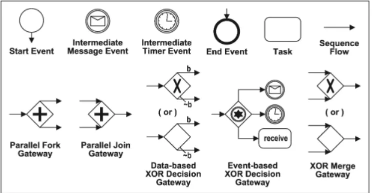
A BPD is made up of BPMN elements as shown in Figure 1. There areobjects andsequence flows. A sequence flow links two objects in a BPD and shows the control flow relation (i.e. execution order). An object can be an event, a task or a gateway. An event may signal the start of a process (start event), the end of a process (end event), a message that arrives, or a specific time-date being reached during a process (intermediate message/timer event). A task is an atomic activity and stands for work to be performed within a process. There are seven task types: service, receive,send,user,script,manual, and reference. For example, a receive task is used when the process waits for a message to arrive from an external partner. Also, a task may be none of the above types, which we refer to as a blank task. A gateway is a routing construct used to control the divergence and convergence of sequence flow. There are: parallel fork gateways for creating concurrent sequence flows, parallel join gateways for synchronizing concurrent sequence flows, data/event-based XOR decision gateways for selecting one out of a set of mutually exclusive alternative sequence flows where the choice is based on either the process data (data-based) or external events (event-based), and XOR merge gateways for joining a set of mutually exclusive alternative sequence flows into one sequence flow. An event-based XOR decision gateway must be followed by either receive tasks or intermediate events to capture race conditions based on timing or external triggers (e.g. the receipt of a message from an external partner). This restriction is not imposed for data-based decision gateways. On the other hand, the outgoing flows of a data-based XOR decision gateway are labelled with conditional expressions, except for one of them which acts as a default flow (depicted by an arrow with a backslash). The default flow is taken if the conditions associated with all other outgoing conditional flows evaluate to false at run time. This ensures that exactly one outgoing flow is taken.
The BPMN elements shown in Figure 1 cover what we call thecoresubset of BPMN. BPMN
defines several other control-flow constructs besides these “core” ones. These include: (1) task looping, (2) multi-instance task, (3) exception flow, (4) sub-process invocation, (5) inclusive OR decision gateway (also called OR-split), and (6)inclusive OR merge gateway (also called OR-join). The mapping of the first five of these “non-core” constructs onto BPEL does not entail additional challenges. Task looping, which corresponds to structured loops can be easily
Figure 1.A set of BPMN elements covering the fundamental control flows in BPMN.
mapped to BPEL “while” activities. Similarly, a multi-instance task can be directly mapped to a “parallel foreach” activity. Sub-processes can be mapped onto separate BPEL processes which call one another. Any OR-split gateway can be expanded into a combination of AND-split and XOR-AND-split gateways [2]. Hence, it does not require a separate mapping rule. On the other hand, the mapping of OR-joins requires a special treatment that falls outside the scope of this work (see Section 7). In the rest of the paper we focus on BPDs composed only of core constructs as per the following definition.
Definition 2 (Core BPD). A core BPD is a tuple BPD= (O, T, E, G, TR, ES, EI, EE,
EI
M, EIT, GF, GJ, GD, GM, GV, F, Cond) where:
– Ois a set of objects which is divided into disjoint sets of tasksT, eventsE, and gatewaysG,
– TR ⊆ T is a set of receive tasks,
– E is divided into disjoint sets of start eventsES, intermediate events EI, and end eventsEE,
– EI is divided into disjoint sets of intermediate message events EI
M and timer events ETI,
– Gis divided into disjoint sets of parallel fork gatewaysGF, join gatewaysGJ, data-based XOR
decision gateways GD, event-based decision gateways GV, and XOR merge gateways GM,
– F ⊆ O × O is the control flow relation, i.e., a set of sequence flows connecting objects,
– Cond: F 9B is a function mapping sequence flows emanating from data-based XOR
deci-sion gateways to conditions,1 i.e. dom(Cond) =F ∩(GD× O).
The relationF defines a directed graph with nodes (objects) O and arcs (sequence flows)
F. For any given nodex ∈ O, input nodes ofx are given byin(x) ={y ∈ O |yFx}and output nodes of x are given by out(x) ={y ∈ O |xFy}.
1 B
is the set of all possible conditions. A condition is a boolean function operating over a set of propositional variables. Note that we abstract from these variables in the control flow definition. We simply assume that a condition evaluates to true or false, which determines whether or not the associated sequence flow is taken during the process execution.
Definition 2 allows for graphs which are unconnected, not having start or end events, con-taining objects without any input and output, etc. Therefore we need to restrict the definition towell-formed core BPDs.
Definition 3 (Well-formed core BPD). A core BPD as defined in Definition 2 is well
formed if relation F satisfies the following requirements:
– ∀ s ∈ ES, in(s) =
∅ ∧ | out(s) | = 1, i.e. start events have an indegree of zero and an
outdegree of one,
– ∀ e ∈ EE, out(e) =
∅ ∧ | in(e) | = 1, i.e., end events have an outdegree of zero and an
indegree of one,
– ∀ x ∈ T ∪ EI, |in(x) | = 1 and |out(x) | = 1, i.e. tasks and intermediate events have an
indegree of one and an outdegree of one,
– ∀ g ∈ GF ∪ GD ∪ GV: | in(g) | = 1 ∧ | out(g) | > 1, i.e. fork and both types of decision
gateways have an indegree of one and an outdegree of more than one,
– ∀g∈ GJ∪GM,|out(g)|= 1 ∧ |in(g)|>1, i.e. join and merge gateways have an outdegree
of one and an indegree of more than one,
– ∀ g ∈ GV, out(g) ⊆ EI ∪ TR, i.e. event-based XOR decision gateways must be followed by
intermediate events or receive tasks,
– ∀g ∈ GD, ∃an order <which is a strict total order over the set of outgoing flows of g (i.e.
{g}×out(g)), and for x ∈ out(g) such that ¬ ∃f∈{g}×out(g)(f<(g,x)), (g,x) is the default flow among all the outgoing flows from g ,
– ∀ x ∈ O, ∃s ∈ ES, ∃e ∈ EE, sF∗x ∧ xF∗e,2 i.e. every object is on a path from a start
event to an end event.
In the remainder we only consider well-formed core BPDs, and will use a simplified notation
BPD = (O,F,Cond) for their representation. Moreover, we assume that bothES and EE are
singletons, i.e. ES ={s} and EE ={e}.3
3 Mapping BPMN onto BPEL
This section presents a mapping from BPMN models to BPEL processes. As mentioned before, the basic idea is to map BPD components onto suitable “BPEL blocks” and thereby to incre-mentally transform a “componentized” BPD into a block-structured BPEL process. We apply
2 F∗
is the reflexive transitive closure ofF, i.e.xF∗y if there is a path fromx toyand by definitionxF∗x.
3 A BPD with multiple start events can be transformed into a BPD with a unique start event by using an
event-based XOR decision gateway. A BPD with multiple end events can be transformed into a BPD with a unique end event by using an OR-join gateway which is however not covered in this paper.
three different approaches to the mapping of components.4 A component may bewell-structured
so that it can be directly mapped onto BPEL structured activities. If a component is not well-structured but is acyclic, it may be possible to map the component to control link-based BPEL code. Otherwise, if a component is neither well-structured nor can be translated using control links (e.g. a component that contains unstructured cycles), the mapping of the component will rely on BPEL event handlers via the usage of event-action rules (this will always work but the resulting BPEL code will be less readable). We identify the above categories of components and introduce the corresponding translation approaches one by one. Finally, we propose the algorithm for mapping an entire BPD onto a BPEL process.
3.1 Decomposing a BPD into Components
We would like to achieve two goals when mapping BPMN onto BPEL. One is to define an algorithm which allows us to translate each well-formed core BPD into a valid BPEL process, the other is to generate readable and compact BPEL code. To map a BPD onto (readable) BPEL code, we need to transform a graph structure into a block structure. For this purpose, we decompose a BPD intocomponents. A component is a subset of the BPD that has one entry point and one exit point. We then try to map components onto suitable “BPEL blocks”. For example, a component holding a purely sequential structure is mapped onto a BPEL sequence
construct while a component holding a parallel structure is mapped onto a flow construct. Below, we formalise the notion of components in a BPD. To facilitate the definitions, we specify an auxiliary function eltover a domain of singletons, i.e., if X={x}, then elt(X)=x.
Definition 4 (Component).LetBPD= (O,F,Cond)be a well-formed core BPD.C=(Oc,
Fc,Condc) is a component of BPD if and only if:
– Oc ⊆ O\(ES ∪ EE), i.e., a component does not have any start or end event,
– |(S
x∈Ocin(x))\Oc | = 1, i.e., there is a single entry point outside the component,
5 which
can be denoted as entry(C) =elt((S
x∈Ocin(x))\Oc),
– | (S
x∈Ocout(x))\Oc | = 1, i.e., there is a single exit point outside the component, which can be denoted as exit(C) =elt((S
x∈Ocout(x))\Oc),
– |out(entry(C))∩ Oc |= 1, i.e., there is a unique source object ic =elt(out(entry(C))∩ Oc),
– |in(exit(C))∩ Oc |= 1, i.e., there is a unique sink object oc=elt(in(exit(C))∩ Oc),
– ic 6=oc,
4
It should be noted that the first two approaches are inspired by the mapping from Petri nets to BPEL as described in [4].
5
Note thatin(x) is not defined with respect to the component but refers to the whole BPD. This also applies toout(x).
– Fc=F ∩(Oc× Oc),
– Condc =Cond[Fc], i.e. the Condfunction where the domain is restricted to Fc.
Note that all event objects in a component are intermediate events. Also, a component con-tains at least two objects: the source object and the sink object. A BPD without any component, which is referred to as a trivial BPD, has only a single task or intermediate event between the start event and the end event. Translating a trivial BPD into BPEL is straightforward and will be covered by the final translation algorithm (see Section 3.5).
The decomposition of a BPD helps to define an iterative approach which allows us to incrementally transform a “componentized” BPD into a block-structured BPEL process. Below, we define the functionFoldthat replaces a component by a single (blank) task object in a BPD. This function can be used to iteratively reduce a componentized BPD until no component is left in the BPD. The function will play a crucial role in the final translation algorithm where we incrementally replace BPD components by BPEL constructs.
Definition 5 (Fold).LetBPD= (O,F,Cond)be a well-formed core BPD andC= (Oc,Fc,Condc)
be a component of BPD. Function Fold replaces C in BPD by a task object tc 6∈ O, i.e.
Fold(BPD,C,tc) =(O0,F0, Cond0) with:
– O0 = (O\O
c)∪ {tc},
– T0 = (T \Oc)∪ {tc} is the set of tasks in Fold(BPD,C,tc),
– TR0
= (TR\O
c) is the set of receive tasks in Fold(BPD,C,tc),
– F0 = (F ∩((O\Oc)×(O\Oc)))∪ {(entry(C),tc),(tc,exit(C))},
– Cond0 =
Cond[F0] if entry(C)6∈ GD
Cond[F0]∪ {((entry(C),tc),Cond(entry(C),ic))} otherwise
3.2 Structured Activity-based Translation
As mentioned before, one of our goals for mapping BPMN onto BPEL is to generate readable BPEL code. For this purpose, BPEL structured activities comprising sequence, flow, if,pick,
while and repeatUntil, have the first preference if the corresponding structures appear in the BPD. Components that have a direct and intuitive correspondence to one of these six structured constructs are considered as well-structured components (WSCs). Below, we classify different types of WSCs resembling these six structured constructs.
Definition 6 (Well-structured components). Let BPD = (O,F,Cond) be a well-formed
core BPD and C = (Oc, Fc, Condc) be a component of BPD. ic is the source object of C and
(a) C is a SEQUENCE-component if Oc ⊆ T ∪ EI (i.e. ∀x ∈ Oc, |in(x)|=|out(x)| = 1) and
entry(C) 6∈ GV. C is a maximal SEQUENCE-component if there is no other SEQUENCE
-componentC0 such that Oc ⊂ Oc0 where Oc0 is the set of objects in C0,
(b) C is a FLOW-component if - ic ∈ GF ∧ oc ∈ GJ,
- Oc ⊆ T ∪ EI ∪ {ic,oc},
- ∀ x ∈ Oc\{ic,oc}, in(x) ={ic} ∧out(x) ={oc}.
(c) C is a IF-component if - ic ∈ GD ∧oc ∈ GM,
- Oc ⊆ T ∪ EI ∪ {i c,oc},
- ∀ x ∈ Oc\{ic,oc}, in(x) ={ic} ∧out(x) ={oc}.
(d) C is a PICK-component if - ic ∈ GV ∧oc ∈ GM,
- Oc ⊆ T ∪ EI ∪ {i c,oc},
- ∀ x ∈ Oc\({ic,oc} ∪out(ic)), in(x)⊆out(ic) ∧ out(x) ={oc}.6
(e) C is a WHILE-component if - ic ∈ GM ∧ oc ∈ GD ∧x ∈ T ∪ EI, - Oc ={ic,oc,x}, - Fc ={(ic,oc),(oc,x),(x,ic)}. (f) C is a REPEAT-component if - ic ∈ GM ∧ oc ∈ GD ∧x ∈ T ∪ EI, - Oc ={ic,oc,x}, - Fc ={(ic,x),(x,oc),(oc,ic)}. (g) C is a REPEAT+WHILE-component if - ic ∈ GM ∧ oc ∈ GD ∧x1,x2 ∈ T ∪ EI ∧ x1 6=x2, - Oc ={ic,oc,x1,x2}, - Fc ={(ic,x1),(x1,oc),(oc,x2),(x2,ic)}.
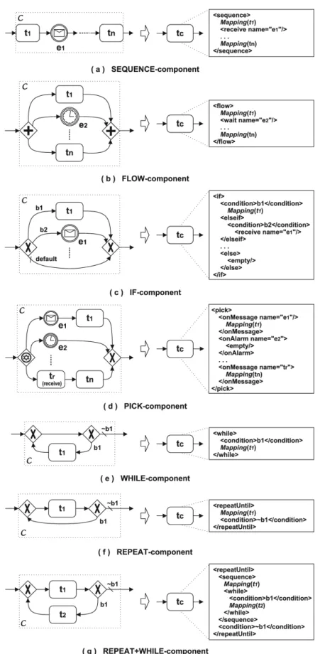
Figure 2 illustrates how to map each of the above WSCs onto the corresponding BPEL structured activities. Using functionFold in Definition 5, a componentCis replaced by a single task tc attached with the corresponding BPEL translation ofC. Note that the BPEL code for
the mapping of each taskti (i = 1, ...,n) is denoted asMapping(ti). Based on the nature of these
task objects they can be mapped onto the proper types of BPEL basic activities. For example, a
6
Note thatout(ic)⊆ TR∪ EI
is the set of receive tasks and intermediate events following the event-based XOR decision gatewayic, i.e. for anyx ∈ TR∪ EI:|in(x)|=|out(x)|= 1. Moreover, between the merge gateway oc and each of the objects inout(ic) there is at most one task or event object.
service task is mapped onto an invoke activity, areceive task (liketr in Figure 2(d)) is mapped
onto a receive activity, and a user task may be mapped onto an invoke activity followed by a receive activity. Since the goal of this paper is to define an approach for translating BPDs with arbitrary topologies to valid BPEL processes, we do not discuss further how to map simple tasks in BPMN onto BPEL. The interested reader may refer to [27] for some guidelines on mapping BPMN tasks into BPEL activities. Finally, the taskti may result from the folding of a previous
component C0, in which case,Mapping(ti) is the code for the mapping of component C0.
With the examples shown in Figure 2, we now generalise the mapping of a given WSC C
using the BPEL syntax defined in Definition 1, as follows:
– ASEQUENCE-component is mapped tosequence([Mapping(x)|x ←[Oc]<]). The notation [Oc]< represents the (sequentially) ordered list of objects in C, and x ← [Oc]< indicates
that each object x is taken in the order as they appear in the list [Oc]<;
– A FLOW-component toflow({Mapping(x)|x ∈ Tc∪ Ec});
– An IF-component to if([(Condc(ic,x),Mapping(x)) | x ← [out(ic)]<]). The source object
ic is the data-based decision gateway in the component, and [out(ic)]< captures the order
of the outgoing (conditional) flows of the gateway so that the conditional branches in the resultingif construct are evaluated in the same order;
– In a PICK-component, an event-based decision gateway must be followed by receive tasks or intermediate message or timer events7. We use function Map2Event to capture the fact that the above receive task or intermediate message will be mapped to a BPEL
msgReceipt event (<onMessage>in BPEL concrete syntax) and the timer event to a BPEL
alarm event (<onAlarm>). Therefore, the mapping of aPICK-component can be written as
pick({(Map2Event(x),Mapping(succ(x))) |x ∈ out(ic)}). Note that for any object x that
has an outdegree of one, succ(x) refers to the only output object ofx;
– A REPEAT-component torepeatUntil(Condc(oc,exit(C)),Mapping(succ(ic)));
– A WHILE-component is mapped to a while construct of while(Condc(oc,x),Mapping(x))
wherex =elt(in(ic)∩out(oc)); and
– A REPEAT+WHILE-component to a while construct of the above being nested within a construct ofrepeatUntil(Condc(oc,exit(C)),sequence([Mapping(succ(ic)),while])).
3.3 Control Link-based Translation
Since BPMN is a graph-oriented language in which nodes can be connected almost arbitrarily, a BPD may contain non-well-structured components, i.e. components that do not match any of
7
For this reason, asequence-component cannot be preceded by an event-based XOR decision gateway (as defined byentry(C)6∈ GV
Figure 2.Mapping a WSCConto a BPEL structured activity and foldingCinto a single task objecttcattached with the BPEL code for mapping.
the “patterns” as defined in Definition 6. Recall that BPEL provides a non-structured construct called control link, which allows for the definition of directed acyclic graphs and thus can be used for the translation of a large subset of acyclic BPD components. As mentioned in Section 2.1, the term “link-based flow construct” is used to refer to a flow activity in which all sub-activities are connected through links to form directed acyclic graphs.
It is important to emphasize two issues related to link semantics. First, the use of control links may hide errors such as deadlocks. This means that the designer makes a modeling error that in other languages would result in a deadlock, however, given the dead-path elimination semantics of BPEL the error is masked. As an example, the use of control links can lead to models where one or several actions are “unreachable”, i.e., these actions will never be executed. The interested reader may refer to [31] for examples of such undesirable models. Second, since an activity cannot “start until the status of all its incoming links has been determined and the, implicit or explicit, join condition has been evaluated” (Section 11.6.2 of [15]), each execution of an activity can trigger at most one execution of any subsequent activity to which it is connected via a control link.
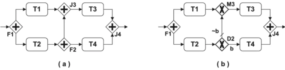
Consider, as shown in Figure 3, the two acyclic components that are not well-structured (in the sense of Definition 6). The one in (a) can be mapped onto a link-based flow construct without any problem.8 However, for the one shown in (b), if condition b does not hold at the data-based decision gateway D2, task T4 will never be performed, causing the component to deadlock at the join gateway J4 (which requires that both tasks T3 and T4 are executed). Also, task T3 will be executed twice, a behavior that cannot be represented using control links which only trigger the target activity at most once.
In Petri net terminology, a component like the one shown in Figure 3 cannot be qualified as being “sound” and “safe”. Intuitively, if a BPD component is sound, it is free from deadlocks and dead tasks (i.e. tasks that can never be executed), and once the component is executed, the execution always starts at the source object and will always reach the sink object. If a BPD component is safe, it implies that any object in the component that is already activated cannot receive another activation signal unless the current activation of the object is completed. Further discussions on soundness and safeness properties within the context of Petri nets are given in Appendix A.3.
8
A model with similar topology as Figure 3(a) has been used in the proof of the existence of “arbitrary, well-behaved, workflow models that cannot be modelled as structured workflow models” on page 438 of [18].
Figure 3. Two non-well-structured acyclic components: (a) can be mapped onto a link-based flow construct, whereas (b) is not sound and safe and therefore cannot be translated.
3.3.1 Components for Control Link-based Translation
We use the term Synchronising Process Component (SPC) to refer to an acyclic component
that is sound and safe and is free from event-based gateways (see Definition 7). Each SPC can be mapped to a link-based flow construct preserving the same semantics. The name SPC is inspired by the concept of synchronising process models, in which “an activity can receive two types of tokens, a true token or a false token. Receipt of a true token enables the activity, while receipt of a false token leads to the activity being skipped and the token to be propagated” [17]. This way the semantics of control links are well captured and thus the activities can be viewed as being connected via control links.
Definition 7 (Synchronising process component). Let C = (Oc,Fc,Condc) be a
compo-nent of a well-formed core BPD. C is an SPC if it satisfies the following three conditions:
(a) There are no cycles(i.e.,∀x ∈ Oc, (x,x)6∈ F∗
c);
(b) There are no event-based gateways (i.e., if GVdenotes the set of event-based gateways in
the BPD, thenOc∩ GV=
∅); and
(c) C is sound and safe (this can be determined based on a Petri net semantics of C).
It is worth noting that some WSCs such asSEQUENCE-component, FLOW-component and IF-component are also SPCs. When mapping a BPD onto BPEL we will always try to use the structured activity-based translation described in Section 3.2, until there are no WSCs left in the BPD. Therefore, the control link-based translation only applies to a subset of SPCs that are not well-structured. In addition, we will always try to detect aminimalSPC for translation. An SPC C= (Oc,Fc,Condc) isminimal if there is no other componentC0= (Oc0,Fc0,Condc0)
such that Oc0 ⊂ Oc. It is easy to discover that such a component always starts with a fork or
data-based decision gateway and ends with a join or merge gateway, given the fact that there are no WSCs left (they have been iteratively removed).
3.3.2 Control Link-based Translation Algorithm
The basic idea behind this algorithm is to translate the control-flow relation between all task and event objects within an SPC into a set of control links. Before translation, it is necessary to pre-process the component using the following two steps. First, as aforementioned, a minimal SPC always has a gateway as its source or sink object. Since control links connects only task or event objects, it is necessary to insert an empty task (i.e. a task of doing nothing) before the source gateway object of the component, and to insert an empty task after the sink gateway object of the component. We call the resulting component a wrapped component.
Definition 8 (Wrapped component). Let C = (Oc,Fc,Condc) be a component of a
well-formed core BPD. By inserting an empty task ah before the source object ic of C and an
empty task at after the sink object oc of C, we obtain the wrapped component of C as being the
component Cw = (Ow,Fw,Condw) where:
– Ow = Oc ∪ {ah,at},
– Fw =Fc∪ {(ah,ic),(oc,at)},
– Condw =Condc
Next, the BPMN specification states that the conditional branches of a data-based decision gateway “should be evaluated in a specific order” (Section 9.5.2 on page 72 of [27]). In more detail, “the first one that evaluates as TRUE will determine the Sequence Flow that will be taken. Since the behavior of this Gateway is exclusive, any other conditions that may actually be TRUE will be ignored”. Also, the default branch, which is always the last branch considered, will be chosen if none of the other branches evaluate to true (see Definition 3). When using control links to replace a data-based decision gateway, we need to ensure that the above semantics of the gateway are preserved. This can be done by refining the conditions on each of the outgoing flows of a data-based decision gateway. We use {f1, ..., fn}to denote the
set of outgoing flows from a data-based decision gateway and use Cond(fi) (16i6n) to denote
the condition on flow fi. Assume that Cond(fi) is evaluated in the order from f1 to fn, andfn
is the default branch. The refined condition on flow fi is given by
RefinedCond(fi) = Cond(f1) i = 1
¬(Cond(f1)∨...∨Cond(fi−1))∧Cond(fi) 1<i<n
¬(Cond(f1)∨...∨Cond(fn−1)) i =n
It is easy to prove that the above pre-processing will not change the behavior of an SPC. We now derive from the structure of a wrapped SPC, the set of control links used to connect all tasks and events in the component. First, we would like to capture the control flow logic
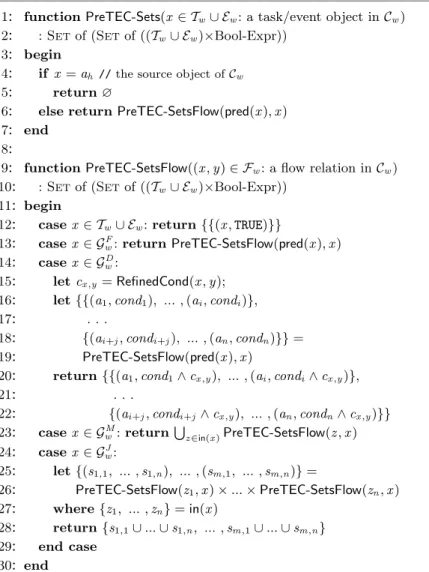
between every two task or event objects that are directly or indirectly (via gateways) connected within the component. To this end, we define two functions as shown in Figure 4. One named PreTEC-Sets(lines 1-7), takes an objectx and generates the set of sets of pairs each containing a preceding task or event and a boolean expression forx. If any data-based decision gateways are involved, the boolean expression is used to capture the conditions specified on the outgoing flows of these gateways; otherwise, it has a boolean value ofTRUEby default. Also, for any object x that has an indegree of one, pred(x) refers to the only input object ofx.
Except for the source object (line 4), PreTEC-Sets relies on the second function named PreTEC-SetsFlow(lines 9-30) to compute the results for all the other objects in the component. The function PreTEC-SetsFlow produces the same type of output asPreTEC-Setsbut takes as input a flow rather than an object. It operates based on the type of the source object of the flow. If the flow’s source is a task or an event (line 21), a set is returned containing a singleton set of a pair comprising that task or event and a default boolean value of TRUEsince there is no
data-based decision gateway on the flow. Otherwise, if the flow’s source is a gateway, the algorithm keeps working backwards through the component, traversing other gateways, until reaching a task or an event. In particular, if a flow originates from a data-based decision gateway (line 14), the (refined) condition on the flow is added via conjunction to each of boolean expressions in the resulting set. This captures the fact that the condition specified on an outgoing flow of a data-based decision gateway is part of each trigger that enables the corresponding object following the gateway. In the case of a flow originating from a merge or a join gateway, the function is recursively called for each of the flows leading to this gateway. For a merge gateway (line 23), the union of the resulting sets captures the fact that whenany of these flows is taken, the gateway may be executed. For a join gateway (line 24), the combination9 of the resulting sets captures the fact that when all of these flows are taken, the gateway may be executed.
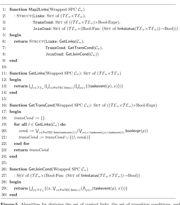
Based on the above, Figure 5 defines an algorithm which derives from a wrapped SPC Cw,
the set of control links for connecting the tasks and events in Cw, the set of transition condi-tions associated with each of the links, and the set of join condicondi-tions associated with each of the tasks and events. The algorithm consists of four functions. The main function Map2Links (lines 1-9) returns the final result by calling three other functions, namelyGetLinks(lines 11-14), GetTransCond (lines 16-24), and GetJoinCond (lines 26-30). A control link is defined as a pair comprising the source and the target objects. A transition condition associated with a control link is a boolean expression that functions as a guard on the link. For a given task or event x, the task or event object in each of the pairs (i.e. (taskevent,boolexpr)) in PreTEC-Sets(x)
rep-9
This is performed by first calculating the cartesian product of a number ofn sets and then converting each element in the resulting set from a tuple of cardinalitynto a set of union of thenelements in the tuple.
————————————————————————————–
1: functionPreTEC-Sets(x∈ Tw∪ Ew: a task/event object inCw)
2: :Setof (Setof ((Tw∪ Ew)×Bool-Expr))
3: begin
4: if x=ah //the source object ofCw
5: return∅
6: else returnPreTEC-SetsFlow(pred(x),x) 7: end
8:
9: functionPreTEC-SetsFlow((x,y)∈ Fw: a flow relation inCw)
10: :Setof (Setof ((Tw∪ Ew)×Bool-Expr))
11: begin
12: casex ∈ Tw∪ Ew:return{{(x,TRUE)}}
13: casex ∈ GF
w:returnPreTEC-SetsFlow(pred(x),x)
14: casex ∈ GD w:
15: letcx,y =RefinedCond(x,y); 16: let{{(a1,cond1), ... ,(ai,condi)},
17: let{ . . .
18: let{{(ai+j,condi+j), ... ,(an,condn)}}=
19: let{PreTEC-SetsFlow(pred(x),x)
20: return{{(a1,cond1∧cx,y), ... ,(ai,condi∧cx,y)},
21: return{ . . .
22: return{{(ai+j,condi+j∧cx,y), ... ,(an,condn∧cx,y)}}
23: casex ∈ GM w :return S z∈in(x)PreTEC-SetsFlow(z,x) 24: casex ∈ GJ w: 25: let{(s1,1, ... ,s1,n), ... ,(sm,1, ... ,sm,n)}=
26: letPreTEC-SetsFlow(z1,x)×...×PreTEC-SetsFlow(zn,x) 27: where{z1, ... ,zn}=in(x)
28: return{s1,1∪...∪s1,n, ... ,sm,1∪...∪sm,n}
29: end case
30: end
————————————————————————————–
Figure 4. Algorithm for deriving the set of preceding tasks or events with conditions sets for any object in a wrapped SPCCw= (Ow,Fw,Condw).
resents the source object of a link; and for this link, its transition condition can be derived as a disjunction of all the boolean expressions in the pairs that share the same task or event as their first element. Next, a join condition associated with a task or event object is specified as a boolean expression over thelinkstatus of each of the links leading to that object. For a given task or event x, the join condition of all the incoming links to x can be derived capturing the fact that a combination (which implies a conjunction) of the links obtained from each set of the pairs in PreTEC-Sets(x), represent an alternative way (which implies a disjunction) to reachx. Now, with the set of links returnd byMap2Links(Cw), we can map the entire componentCw
onto a link-based flow construct. The mapping of each task or event objectx inCw is denoted
as Mapping(x). Using the BPEL syntax given in Definition 1, the resulting link-based flow construct can be written as link-flow(Map2Links(Cw),{Mapping(x)|x ∈ Tw∪ Ew}).
Finally, it is important to mention the interplay between the structured activity-based approach (Section 3.2) and the control link-based approach for translating BPDs into BPEL. First, the structured activity-based translation is applied iteratively. If there are no longer
———————————————————————————————————–
1: functionMap2Links(Wrapped SPCCw)
2: :Struct(Links:Setof (T Ew×T Ew),
3: :StructTransCond:Setof ((T Ew×T Ew)×Bool-Expr),
4: :StructJoinCond:Setof (T Ew×(Bool-Fun: (Setoflinkstatus(T Ew×T Ew))→Bool)))
5: begin
6: returnStruct(Links:GetLinks(Cw),
7: returnStructTransCond:GetTransCond(Cw),
8: returnStructJoinCond:GetJoinCond(Cw))
9: end
10:
11: functionGetLinks(Wrapped SPCCw):Setof (T Ew×T Ew)
12: begin 13: returnS x∈T Ew( S s∈PreTEC-Sets(x)( S p∈s{(taskevent(p),x)})) 14: end 15:
16: functionGetTransCond(Wrapped SPCCw):Setof ((T Ew×T Ew)×Bool-Expr)
17: begin
18: transCond:={}
19: for alll∈GetLinks(Cw)do
20: condl :=W
s∈PreTEC-Sets(taskevent(l))(
W
p∈s∧taskevent(p)=taskevent(l)boolexpr(p))
21: transCond:=transCond∪ {(l,condl)} 22: end for
23: returntransCond
24: end
25:
26: functionGetJoinCond(Wrapped SPCCw)
27: :Setof (T Ew×(Bool-Fun: (Setoflinkstatus(T Ew×T Ew))→Bool))
28: begin 29: returnS x∈T Ew{(x, W s∈PreTEC-Sets(x)( V p∈s(taskevent(p),x)))} 30: end ———————————————————————————————————–
Figure 5. Algorithm for deriving the set of control links, the set of transition conditions, and the set of join conditions from a wrapped SPC.
WSCs, the control link-based translation is used. Applying the control link-based translation may again enable a structured activity-based translation, etc. Hence it is possible that both types of reductions alternate. Unfortunately, there are BPDs that cannot be translated into BPEL using these two approaches. The next subsection shows a “brute force” approach that can be used as a last resort, i.e., it always works but may lead to less readable models.
3.4 Event-Action Rule-based Translation
A well-formed core BPD may also contain components that are neither well-structured nor can be translated using control links. For example, a component capturing a multi-merge pattern, which allows each incoming branch to continue independently of the others thus enabling multiple threads of execution on the subsequent branch [2], or an unstructured loop, i.e., a loop
can be used to translate such component into ascopeactivity by exploiting the “event handler” construct in BPEL. Since an event handler is an event-action rule associated with a scope, we name the approach, in a more general sense, event-action rule-based translation approach. It should be mentioned that this approach can be applied to translating any component to BPEL. However, it produces less readable BPEL code and hence we resort to this approach only when there are no components left in the BPD, which are either well-structured or which can be translated using control links.
The basic idea behind the event-action rule-based approach is to map each object (task, event or gateway) onto event handler(s). An incoming flow of the object captures the “event” of receiving a message which triggers the corresponding event handler. The actions taken by the event handler must ensure to invoke (i.e. send) message(s) signaling the completion of the object execution. Note that the word “event” we mention here refers to the event within the context of event-action rules, and therefore is different from BPMN event objects.
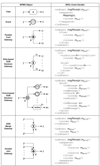
Figure 6 illustrates how to map each type of BPMN objects onto BPEL event handlers. We use m(y,x) to denote a message that is created once the sequence flow connecting objecty
to object x is taken. This message signals the completion of y so that the execution ofx may start. The event of receiving a messagem(y,x)can be written asmsgReceipt(m(y,x)). Each task, event, fork gateway, or decision gateway object is mapped onto one event handler, which is triggered upon the receipt of the message from the only incoming flow of the object. For a task or event object x, let z denote the only output object of x, the resulting event handler first executes x (whose mapping is denoted as Mapping(x)), and then invokes the message m(x,z)
once the sequence flow from object x to object z is taken, signaling the completion of the execution of x. For a fork or decision gateway, the resulting event handler invokes a number of messages to capture the outgoing flows in order as defined by the gateway. To this end, the BPEL flow activity is used for the mapping of a fork gateway, the if activity is used for a data-based decision gateway, and the pick activity is used for an event-based decision gateway with the immediately followed events and/or receive tasks. Next, a merge gateway is mapped onto multiple event handlers in a way that each of them can be triggered upon the receipt of the message fromone of the multiple incoming flows of the gateway. Finally, for a join gateway, the mapping is less straightforward because BPEL only supports the situation where an event handler is triggered by the occurrence of asingle event. As shown in Figure 6, a join gatewayx
can be mapped onto one event handler by separating, for example, the receipt of the message (m(y1,x)) on the first incoming flow, from those (m(y2,x), ...,m(yn,x)) on the rest of the incoming flows. Although the resulting event handler can be triggered by the receipt of messagem(y1,x),
Figure 6.Mapping BPMN objects onto BPEL event handlers.
the real action, i.e. invoking the message m(x,z), will not be performed until all the remaining messages m(y2,x) tom(yn,x) have been received.
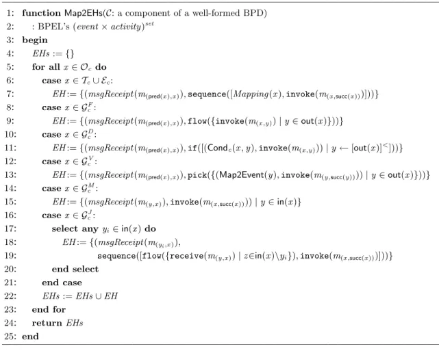
Based on the above, Figure 7 defines a function named Map2EHs which takes as input a componentCin a well-formed core BPD, and returns the set of event handlers as the mappings of all the objects inC. The resulting code is written in BPEL syntax as defined in Definition 1. With the set of event handlers returned by Map2EHs(C), we can then map the entire compo-nent C onto a BPEL scope construct. Letm(entry(C),ic) denote the message being created once
the sequence flow is taken which connects from the entry point entry(C) (outside the compo-nent C) to the source object ic. Using the BPEL syntax definition, the resulting scope can be
written as scope(Map2EHs(C),invoke(m(entry(C),ic))). Here, the main activity of the scope is
—————————————————————————————————————————–
1: functionMap2EHs(C: a component of a well-formed BPD) 2: : BPEL’s (event×activity)set
3: begin
4: EHs:={} 5: for allx ∈ Oc do
6: casex ∈ Tc∪ Ec:
7: EH:={(msgReceipt(m(pred(x),x)),sequence([Mapping(x),invoke(m(x,succ(x)))]))}
8: casex ∈ GF c:
9: EH:={(msgReceipt(m(pred(x),x)),flow({invoke(m(x,y))|y∈out(x)}))}
10: casex ∈ GD c:
11: EH:={(msgReceipt(m(pred(x),x)),if([(Condc(x,y),invoke(m(x,y)))|y←[out(x)]<]))}
12: casex ∈ GV c :
13: EH:={(msgReceipt(m(pred(x),x)),pick({(Map2Event(y),invoke(m(y,succ(y))))|y∈out(x)}))}
14: casex ∈ GM c :
15: EH:={(msgReceipt(m(y,x)),invoke(m(x,succ(x))))|y∈in(x)}
16: casex ∈ GJ c:
17: select any yi ∈in(x)do
18: EH:={(msgReceipt(m(yi,x)),
19: EH:={sequence([flow({receive(m(y,x))|z∈in(x)\yi}),invoke(m(x,succ(x)))]))}
20: end select 21: end case 22: EHs:=EHs∪EH 23: end for 24: returnEHs 25: end —————————————————————————————————————————– Figure 7.Algorithm for deriving the set of event handlers from a well-formed BPD component.
object ic will be triggered. Then, the event handlers for the remaining objects will be executed
according to the execution order specified inC. Finally, the entire scope will complete after the executions of its main activity and all active event handlers are completed.
3.5 Overall Translation Algorithm
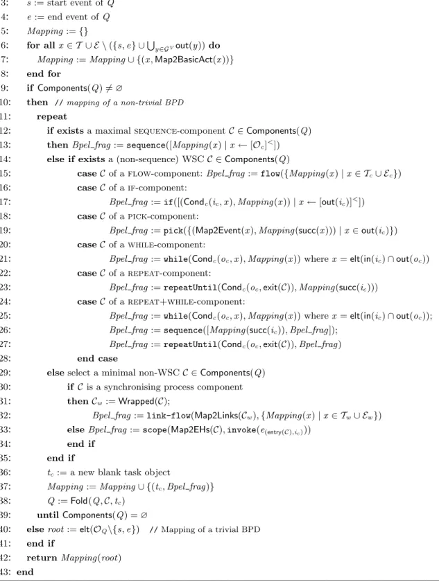
Based on the mapping of each of the components aforementioned, we define an algorithm for translating a well-formed core BPD into BPEL. Figure 8 shows this algorithm, namely BPD2BPEL, which takes a well-formed core BPDQwith one start eventsand one end evente, and produces the resulting mapping to a BPEL process. Let OQ denote the set of objects
in Q, andComponents(Q) the set of components in Q. The translation procedure starts with mapping each primitive task and each event that is not immediately preceded by an event-based decision gateway onto BPEL basic activities. This is denoted by functionMap2BasicAct. Also, for a given object x, the mapping ofx to BPEL is given by Mapping(x). Next, if Q contains at least one component (i.e. Q is a non-trivial BPD), the basic idea is to select a component in Q, provide its BPEL translation, and fold the component (lines 12-39). This is repeated until no component is left in Q (i.e. Q is a trivial BPD). The translation of a trivial BPD is straightforward, which involves the mapping of the only object (root) between the start and
—————————————————————————————————————————–
1: functionBPD2BPEL(Well-formed core BPDQ): BPEL process 2: begin 3: s:= start event ofQ 4: e:= end event ofQ 5: Mapping:={} 6: for allx ∈ T ∪ E \({s,e} ∪S y∈GVout(y))do
7: Mapping:=Mapping∪ {(x,Map2BasicAct(x))} 8: end for
9: if Components(Q)6=∅
10: then //mapping of a non-trivial BPD
11: repeat
12: if existsa maximalsequence-componentC ∈Components(Q) 13: thenBpel frag:=sequence([Mapping(x)|x ←[Oc]<])
14: else if existsa (non-sequence) WSCC ∈Components(Q)
15: caseC of aflow-component:Bpel frag:=flow({Mapping(x)|x ∈ Tc∪ Ec})
16: caseC of aif-component:
17: caseC Bpel frag:=if([(Condc(ic,x),Mapping(x))|x ←[out(ic)]<])
18: caseC of apick-component:
19: caseC Bpel frag:=pick({(Map2Event(x),Mapping(succ(x)))|x∈out(ic)}) 20: caseC of awhile-component:
21: caseC Bpel frag:=while(Condc(oc,x),Mapping(x)) wherex=elt(in(ic)∩out(oc))
22: caseC of arepeat-component:
23: caseC Bpel frag:=repeatUntil(Condc(oc,exit(C)),Mapping(succ(ic)))
24: caseC of arepeat+while-component:
25: caseC Bpel frag:=while(Condc(oc,x),Mapping(x)) wherex=elt(in(ic)∩out(oc));
26: caseC Bpel frag:=sequence([Mapping(succ(ic)),Bpel frag]); 27: caseC Bpel frag:=repeatUntil(Condc(oc,exit(C)),Bpel frag)
28: end case
29: elseselect a minimal non-WSCC ∈Components(Q) 30: if C is a synchronising process component 31: thenCw:=Wrapped(C);
32: thenBpel frag:=link-flow(Map2Links(Cw),{Mapping(x)|x ∈ Tw∪ Ew})
33: elseBpel frag:=scope(Map2EHs(C),invoke(e(entry(C),ic)))
34: end if
35: end if
36: tc:= a new blank task object
37: Mapping:=Mapping∪ {(tc,Bpel frag)} 38: Q:=Fold(Q,C,tc)
39: untilComponents(Q) =∅
40: elseroot:=elt(OQ\{s,e}) //Mapping of a trivial BPD 41: end if
42: returnMapping(root) 43: end
—————————————————————————————————————————– Figure 8.Algorithm for translating a well-formed core BPD into a BPEL process.
the end events in the BPD (line 40). The resulting BPEL process can be then retrieved from
Mapping(root) (line 42).
In more details, for a non-trivial BPD, the component mapping always starts from a max-imal SEQUENCE-component after each folding (lines 12 to 13). When there are no sequences left in the BPD, other WSCs are processed (lines 14 to 28). Since all non-sequence WSCs are disjoint, the order of mapping these components is irrelevant. Next, when no WSCs are left, the algorithm selects a minimal non-WSC for translation (line 19). Note that C is a minimal
non-WSC, if within the same BPD there is no other component C0 such that the set of nodes in C0 is a subset of the set of nodes in C. The algorithm selects a minimal non-WSC C and not a maximal one to avoid missing any “potential” WSC that may appear after the folding of C. This means that there is always a preference for smaller structured activities rather than large flows. The algorithm then checks if C is a SPC so that the control link-based translation approach can be applied (lines 30-32). Note that as part of the SPC identification, one needs to check if the component is sound and safe. This can be done by mapping the component into a Petri net and then checking the soundness and safeness properties of this Petri net (see Appendix A). Also, for any well-formed BPD component, the function Wrapped returns the correspondingly wrapped component as defined in Definition 8. Next, if C is not a SPC, the event-action rule-based translation approach is used as a last resort (line 33). Using the event-action rule-based translation only as a last resort, reflects the desire to produce readable BPEL code. In most cases, event-action rule-based translations can be avoided or play a minor part in the translation. This is illustrated by the two examples in the next section and by the empirical evaluation presented in Section 5.
With the above algorithm, a non-trivial well-formed core BPD can always be componentized and each component is either a WSC or a non-WSC. Every WSC or non-WSC can be mapped onto a certain BPEL construct or a combination of BPEL constructs according to the algorithm. By following-up every mapping operation with a corresponding folding operation the source BPD is gradually simplified and ultimately reduced to a trivial BPD. As part of this process, the target BPEL code is gradually excluded and finalized when the trivial BPD is mapped.
4 Examples
This section provides two examples of business process models in BPMN. We show how these two models can be translated into BPEL using the algorithm presented in the previous section.
4.1 Example 1: Complaint Handling Process
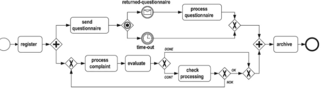
Consider the complaint handling process model shown in Figure 9. It is described as a well-formed core BPD. First the complaint is registered (task register), then in parallel a ques-tionnaire is sent to the complainant (task send questionnaire) and the complaint is processed (task process complaint). If the complainant returns the questionnaire in two weeks (event
returned-questionnaire), task process questionnaire is executed. Otherwise, the result of the questionnaire is discarded (event time-out). In parallel the complaint is evaluated (task eval-uate). Based on the evaluation result, the processing is either done or continues to task check processing. If the check result is not OK, the complaint requires re-processing. Finally, task
archive is executed. Note that labelsDONE,CONT,OK and NOK on the outgoing flows of each data-based XOR decision gateway, are abstract representations of conditions on these flows.
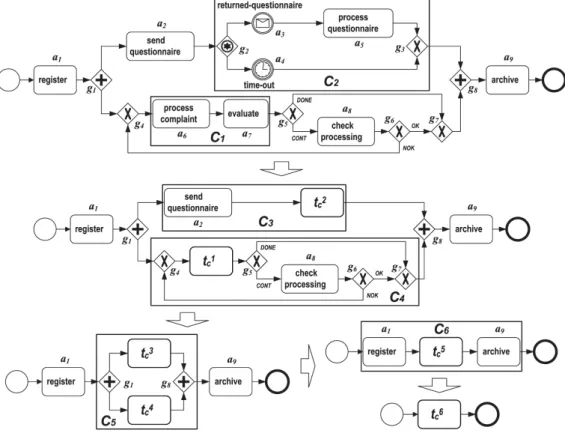
Following the algorithm in Section 3, we now translate the above BPD to BPEL. Figure 10 sketches the translation procedure which shows how this BPD can be reduced to a trivial BPD. Six components are identified. Each component is named Ci where i specifies in what order
the components are processed, andCi is folded into a task object named tci. Also, we assign an
identifier ai to each task or intermediate event andgi to each gateway in the initial BPD. We
use these identifiers to refer to the corresponding objects in the following translation. It should be mentioned that since we focus on the control-flow perspective, the resulting BPEL process definition is presented in simplified BPEL syntax which defines the control flow for the process and omits the details related to data definitions such as partners, messages and variables.
1st Translation. The algorithm first tries to locate SEQUENCE-components. In the initial
BPD shown in Figure 9, component C1 consisting of tasks a6 and a7 is the only SEQUENCE-component that can be identified. Hence, C1 is folded into a tasktc1 attached with the BPEL
translation sketched as:
<sequence name="tc1">
<invoke name="process complaint".../> <invoke name="evaluate".../>
</sequence>
Figure 10.Translating the complaint handling process model in Figure 9 into BPEL.
2nd Translation. When no SEQUENCE-components can be identified, the algorithm tries to
discover any non-sequence WSC. As a result, componentC2is selected. It is aPICK-component and is folded into a task tc2 attached with the BPEL code sketched as:
<pick name="tc2">
<onMessage operation="returned-questionnaire"...> <invoke name="process questionnaire".../> </onMessage>
<onAlarm for=‘P14DT’> <empty/>
</onAlarm> </pick>
Assume that the maximal waiting period for the returned questionnaire is two weeks, i.e. 14 days. In BPEL, this is encoded as P14DT.
3rd Translation. Folding C2 into tc2 introduces a new SEQUENCE-component C3 consisting
of tasksa2 andtc2.C3 is folded into a tasktc3 attached with the BPEL translation sketched as:
<sequence name="tc3">
<invoke name="send questionnaire".../> <pick name="t2
c">...</pick>
4th Translation. After the above three components C1 to C3 have been folded into the corresponding tasks tc1 totc3, there is no WSCs left in the BPD. The algorithm continues to identify any minimal non-WSC. As a result, the component C4 is selected. Since C4 contains cycles, it is not a SPC. Below, we map C4 onto a scope with event handlers.
<scope name="tc4"> <!-- mapping of g4 --> <onEvent msgReceipt(m(g1,g4))> <invoke m(g4,t1 c)/> </onEvent> <onEvent msgReceipt(m(g6,g4))> <invoke m(g4,tc1)/> </onEvent> <!-- mapping of tc1 --> <onEvent msgReceipt(m(g4,t1 c))> <sequence>
<sequence name="tc1"> ...</sequence> <invoke m(t1 c,g5)/> </sequence> </onEvent> <!-- mapping of g5 --> <onEvent msgReceipt(m(t1 c,g5))> <if>
<case condition="branchVar=‘DONE’"> <invoke m(g5,g7)/>
</case>
<case condition="branchVar=‘CONT’"> <invoke m(g5,a8)/> </case> </if> </onEvent> <!-- mapping of a8 --> <onEvent msgReceipt(m(g5,a8))> <sequence>
<invoke name="check processing".../> <invoke m(a8,g6)/> </sequence> </onEvent> <!-- mapping of g6 --> <onEvent msgReceipt(m(a8,g6))> <if> <case condition="branchVar=‘OK’"> <invoke m(g6,g7)/> </case>
<invoke m(g6,g4)/> </case> </if> </onEvent> <!-- mapping of g7 --> <onEvent msgReceipt(m(g5,g7))> <invoke m(g7,g8)/> </onEvent> <onEvent msgReceipt(m(g6,g7))> <invoke m(g7,g8)/> </onEvent>
<!-- to trigger source object g4 -->
<invoke m(g1)/> </scope>
5th Translation. Folding C3 to tc3 and C4 to tc4 introduces a FLOW-component C5. C5 is
folded into a task t5
c attached with the BPEL code sketched as:
<flow name="tc5">
<sequence name="tc3"> ... </sequence> <scope name="tc4"> ... </scope>
</flow>
6th Translation. After C5 has been folded intotc5, a new SEQUENCE-componentC6 is
intro-duced. This is also the only component left between the start event and the end event in the BPD. Folding C6 into task tc6 leads to the end of the translation, and the final BPEL process
is sketched as:
<process name="complaint handling"> <sequence name="t6
c">
<invoke name="register"> <flow name="tc5"> ... </flow> <invoke name="archive"> </sequence>
</process>
4.2 Example 2: Order Fulfillment Process
Figure 11 depicts an order fulfillment process at the customer side using BPMN. The process starts by making a choice between two conditional branches, depending on whether the shipper supports the Universal Business Language (UBL) or the Electronic Data Interchange (EDI) standard. The choice between these two standards is exclusive and EDI is always the default one to choose. If UBL is used, the process needs to receive both the despatch advice and the invoice from the shipper before it can continue. Alternatively, if EDI is used, the process needs
to receive both EDI 856 for the Advanced Shipment Notice (ASN) and EDI 810 for the Invoice before it can proceed. Next, upon the receipt of either EDI 810 or the invoice (formatted in UBL), a payment request can be sent to the shipper. Once the payment request has been sent out and either EDI 856 or the despatch advice (formatted in UBL) has been received, the customer sends the fulfillment notice and then the process completes.
Figure 11.An order fulfillment process model.
Figure 12 sketches how the above BPD can be reduced to a trivial BPD. In total two components are identified. Below, we describe the translation procedure step by step.
Figure 12.Translating the order fulfillment process model in Figure 11 into BPEL.
1st Translation. Initially, no WSCs can be detected in the BPD shown in Figure 11.
Compo-nent C1 consisting of tasksa1 toa5 is the only minimal non-WSC identified. Since it is acyclic, has no event-based gateway, and is also proven to be sound and safe (see Appendix A), the component C1 is a SPC and can be mapped to a link-based flow construct.
First, we pre-process the component C1 as illustrated in Figure 13. Two empty tasks ah
andat are inserted respectively before the data-based decision gatewayd1 (source object ofC1) and after the join gateway j6 (sink object of C1). This way we obtain a wrapped component of C1. Also, the conditions on the outgoing flows of d1 are refined. The component C1, after the above pre-processing, is then renamed C10.
Figure 13.Pre-processing the componentC1 shown in Figure 12.
Second, we generate the set of preceding tasks with conditions sets for each task object in component C10 (C10 has no event objects). There are totally seven sets as listed below:
PreTEC-Sets(ah) =∅,
PreTEC-Sets(a1) =PreTEC-Sets(a2) ={{(ah,UBL)}},
PreTEC-Sets(a3) =PreTEC-Sets(a4) ={{(ah,¬UBL∧EDI)}},
PreTEC-Sets(a5) ={{(a2,TRUE)},{(a4,TRUE)}}, and
PreTEC-Sets(at) ={{(a1,TRUE), (a5,TRUE)},{(a3,TRUE), (a5,TRUE)}}
Third, we derive the set of control links for connecting all the tasks in C10, the set of transition conditions associated with the links, and the join conditions for each of the tasks.
Map2Links(C10) =
Struct(Links:{(ah,a1),(ah,a2),(ah,a3),(ah,a4),
Struct(Links:{(a2,a5),(a4,a5),(a1,at),(a3,at),(a5,at)})
Struct(TransCond:{((ah,a1),UBL),((ah,a2),UBL),
Struct(TransCond:{((ah,a3),¬UBL∧EDI),((ah,a4),¬UBL∧EDI),
Struct(TransCond:{((a2,a5),TRUE),((a4,a5),TRUE),
Struct(TransCond:{((a1,at),TRUE),((a3,at),TRUE),((a5,at),TRUE))
Struct(JoinCond:{(ah,TRUE),(a1,linkstatus(ah,a1)),(a2,linkstatus(ah,a2)),
Struct(JoinCond:{(a3,linkstatus(ah,a3)),(a4,linkstatus(ah,a4)),
Struct(JoinCond:{(a5,linkstatus(a2,a5)∨linkstatus(a4,a5)),
Struct(JoinCond:{(at,(linkstatus(a1,at)∨linkstatus(a3,at))∧linkstatus(a5,at))}
Note that task ah is the source object of component C10 and has no incoming links. Hence,
JoinCond(ah) = TRUE implies that no join condition needs to be specified for ah in the
corre-sponding BPEL definition.
Finally, based on the above, component C1 can be folded into a task tc1 attached with the
BPEL translation sketched as:
<flow name="tc1"> <links>