Data-Over-Cable Service Interface Specifications
Business Services over DOCSIS
®
Layer 2 Virtual Private Networks
CM-SP-L2VPN-I12-131120
ISSUED
Notice
This DOCSIS specification is the result of a cooperative effort
undertaken at the direction of Cable Television Laboratories, Inc. for the benefit of the cable industry and its customers. This document may contain references to other documents not owned or controlled by CableLabs®. Use and understanding of this document may require access to such other documents. Designing, manufacturing, distributing, using, selling, or servicing products, or providing services, based on this document may require intellectual property licenses from third parties for technology referenced in this document.
Neither CableLabs nor any member company is responsible to any party for any liability of any nature whatsoever resulting from or arising out of use or reliance upon this document, or any document referenced herein. This document is furnished on an "AS IS" basis and neither CableLabs nor its members provides any representation or warranty, express or implied, regarding the accuracy, completeness,
noninfringement, or fitness for a particular purpose of this document, or any document referenced herein.
DISCLAIMER
This document is published by Cable Television Laboratories, Inc. ("CableLabs®").
CableLabs reserves the right to revise this document for any reason including, but not limited to, changes in laws, regulations, or standards promulgated by various agencies; technological advances; or changes in equipment design, manufacturing techniques, or operating procedures described, or referred to, herein. CableLabs makes no
representation or warranty, express or implied, with respect to the completeness, accuracy, or utility of the document or any information or opinion contained in the report. Any use or reliance on the information or opinion is at the risk of the user, and CableLabs shall not be liable for any damage or injury incurred by any person arising out of the completeness, accuracy, or utility of any information or opinion contained in the document.
This document is not to be construed to suggest that any affiliated company modify or change any of its products or procedures, nor does this document represent a commitment by CableLabs or any cable member to purchase any product whether or not it meets the described characteristics. Nothing contained herein shall be construed to confer any license or right to any intellectual property, whether or not the use of any information herein necessarily utilizes such intellectual property. This document is not to be construed as an endorsement of any product or company or as the adoption or promulgation of any guidelines, standards, or recommendations.
Document Status Sheet
Document Control Number: CM-SP-L2VPN-I12-131120Document Title: Layer 2 Virtual Private Networks Revision History: I01 – Released March 28, 2006
I02 – Released July 28, 2006 I03 – Released December 22, 2006 I04 – Released May 18, 2007 I05 – Released August 3, 2007 I06 – Released December 6, 2007 I07 – Released February 15, 2008 I08 – Released May 22, 2008 I09 – Released June 11, 2010 I10 – Released October 04, 2012 I11 – Released August 8, 2013 I12 – Released November 20, 2013
Date: November 20, 2013 Status: Work in
Progress
Draft Issued Closed
Distribution Restrictions: Focus Team Only
CL/Member CL/ Member/ Vendor
Public
Key to Document Status Codes:
Work in Progress An incomplete document, designed to guide discussion and generate feedback, that may include several alternative requirements for consideration.
Draft A document in specification format considered largely complete, but lacking review by Members and vendors. Drafts are susceptible to substantial change during the review process.
Issued A generally public document that has undergone Member and Technology Supplier review, cross-vendor interoperability, and is for Certification testing if applicable. Issued Specifications are subject to the Engineering Change Process. Closed A static document, reviewed, tested, validated, and closed to further engineering
change requests to the specification through CableLabs.
Trademarks
CableLabs® is a registered trademark of Cable Television Laboratories, Inc. Other CableLabs marks are listed at
Contents
1 INTRODUCTION ... 9 1.1 Requirements ... 9 1.2 Conformance ... 9 1.3 Conventions ... 10 2 REFERENCES ... 11 2.1 Normative References ... 11 2.2 Informative References ... 12 2.3 Reference Acquisition ... 133 TERMS AND DEFINITIONS ... 14
4 ABBREVIATIONS AND ACRONYMS ... 16
5 THEORY OF OPERATION (INFORMATIVE)... 19
5.1 L2VPN Features ... 19
5.1.1 Transparent LAN Service ... 19
5.1.2 Multiple ISP L2VPNs ... 21
5.1.3 Management L2VPNs ... 21
5.1.4 Other L2VPN-enabled Features ... 22
5.1.5 High Availability ... 22
5.2 CMTS Layer 2 Forwarding Architecture ... 23
5.2.1 L2VPN and Non-L2VPN Forwarding ... 23
5.2.2 Point-to-Point and Multipoint L2VPN Forwarding Modes ... 24
6 L2VPN OPERATION (NORMATIVE) ... 27
6.1 CMTS Bridging Model Requirements ... 27
6.2 Configuring L2VPN Forwarding ... 27
6.2.1 VPNID Subtype ... 30
6.2.2 Downstream Classifier L2VPN Encoding ... 31
6.2.3 L2VPN SA-Descriptor Subtype ... 31
6.2.4 Vendor-Specific L2VPN Encoding ... 32
6.2.5 Configuration Error Requirements ... 32
6.2.6 Network System Interface (NSI) Encapsulation ... 32
6.2.7 Virtual Private LAN Service (VPLS) and Virtual Private Wire Service ... 34
6.3 CMTS Upstream L2VPN Forwarding ... 38
6.4 CMTS Downstream L2VPN Forwarding ... 39
6.4.1 Multipoint Downstream Forwarding ... 40
6.4.2 DOCSIS 3.0 L2VPN Downstream Multicast Forwarding ... 41
6.5 L2VPN Isolation and Privacy ... 41
6.5.1 Protecting L2VPN Traffic ... 41
6.5.2 Preventing Leaking of non-L2VPN Traffic ... 42
6.6 CM and eSAFE Exclusion ... 43
6.6.1 CM and eSAFE Host Forwarding Model ... 43
6.6.2 Cable Modem MAC Bridge Interface Masks ... 44
6.6.3 Embedded Host Exclusion ... 45
6.6.4 CMTS embedded host MAC Address Learning ... 45
6.6.5 Interface-based Classification ... 46
6.7 L2VPN Quality Of Service ... 46
6.7.1 DOCSIS QoS ... 47
6.7.2 Backbone Network QoS ... 47
6.8 Stacked 802.1Q Tags or Tag-in-Tag operation ... 49
6.9 Spanning Tree and Loop Detection ... 49
6.10.1 802 Encapsulation - Active/Standby Layer 2 Trunk Ports ... 50
6.10.2 802 Encapsulation - Link Aggregation ... 50
6.10.3 MPLS Encapsulation High Availability ... 50
6.11 MPLS Encapsulation - PW Redundancy ... 51
7 CABLE MODEM REQUIREMENTS ... 52
8 SERVICE OPERATIONS, ADMINISTRATION, AND MAINTENANCE (OAM) ... 54
8.1 Introduction ... 54
8.2 Service OAM Configuration ... 54
8.2.1 CM ... 54
8.2.2 CMTS ... 54
8.3 Fault Management ... 55
8.3.1 Continuity Check Messages (CCM) ... 55
8.3.2 Loopback ... 55
8.3.3 Linktrace ... 56
8.4 Performance Management ... 56
9 LAYER 2 CONTROL PROTOCOL HANDLING ... 57
ANNEX A CMTS DOCS-L2VPN-MIB REQUIREMENTS (NORMATIVE) ... 58
A.1 DOCS-L2VPN-MIB Conformance ... 58
A.2 DOCS-L2VPN-MIB Definitions ... 62
ANNEX B PARAMETER ENCODINGS (NORMATIVE) ... 84
B.1 Capabilities ... 84
B.1.1 L2VPN Capability ... 84
B.1.2 Embedded Service/Application Functional Entity (eSAFE) Host Capability ... 84
B.1.3 Downstream Unencrypted Traffic (DUT) Filtering ... 84
B.2 Downstream Unencrypted Traffic (DUT) Filtering Encoding ... 84
B.2.1 Downstream Unencrypted Traffic (DUT) Control ... 85
B.2.2 Downstream Unencrypted Traffic (DUT) CMIM ... 85
B.3 L2VPN Encoding... 85
B.3.1 VPN Identifier ... 86
B.3.2 NSI Encapsulation Subtype ... 87
B.3.3 eSAFE DHCP Snooping ... 92
B.3.4 CM Interface Mask (CMIM) Subtype... 92
B.3.5 Attachment Group ID ... 93
B.3.6 Source Attachment Individual ID ... 93
B.3.7 Target Attachment Individual ID ... 93
B.3.8 Upstream User Priority ... 94
B.3.9 Downstream User Priority Range ... 94
B.3.10 L2VPN SA-Descriptor Subtype ... 94
B.3.11 Vendor Specific L2VPN Subtype ... 95
B.3.12 Pseudowire ID (deprecated) ... 95
B.3.13 Pseudowire Type ... 95
B.3.14 L2VPN Mode ... 95
B.3.15 Tag Protocol Identifier (TPID) Translation ... 96
B.3.16 L2CP Processing ... 97
B.3.17 DAC Disable/Enable Configuration ... 98
B.3.18 Pseudowire Class ... 98
B.3.19 Service Delimiter ... 98
B.3.20 Virtual Switch Instance Encoding ... 100
B.3.21 BGP Attribute sub TLV ... 101
B.3.22 VPN-SG Attribute sub TLV ... 102
B.3.23 Pseudowire Signaling ... 102
B.3.25 Network Timing Profile Reference ... 106 B.3.26 L2VPN DSID ... 106 B.4 Confirmation Codes ... 106 B.5 L2VPN Error Encoding ... 107 B.5.1 L2VPN Errored Parameter ... 107 B.5.2 L2VPN Error Code ... 107 B.5.3 L2VPN Error Message... 108
B.6 CM Interface Mask Classification Criteria ... 108
B.7 L2VPN MAC Aging Encoding ... 109
B.7.1 L2VPN MAC Aging Mode ... 109
APPENDIX I EXAMPLE L2VPN ENCODINGS (INFORMATIVE) ... 111
I.1 Point-to-Point Example... 111
I.2 Multipoint Example ... 114
I.3 Upstream L2VPN Classifier Example ... 117
APPENDIX II IEEE 802.1Q ENCAPSULATION (INFORMATIVE)... 119
APPENDIX III EMBEDDED VLAN CM BRIDGING MODEL (INFORMATIVE) ... 120
III.1 IEEE 802.1Q and Embedded VLAN Model ... 121
III.2 Embedded Bridge MAC Domain Service Primitives ... 122
APPENDIX IV L2VPN NON-COMPLIANT CM RESTRICTIONS (INFORMATIVE) ... 124
IV.1 Leaking through non-compliant CMs ... 124
APPENDIX V ACKNOWLEDGEMENTS (INFORMATIVE) ... 125
APPENDIX VI REVISION HISTORY (INFORMATIVE)... 126
VI.1 Engineering Change for CM-SP-L2VPN-I02-060728 ... 126
VI.2 Engineering Change for CM-SP-L2VPN-I03-061222 ... 126
VI.3 Engineering Change for CM-SP-L2VPN-I04-070518 ... 126
VI.4 Engineering Changes for CM-SP-L2VPN-I05-070803 ... 126
VI.5 Engineering Changes for CM-SP-L2VPN-I06-071206 ... 126
VI.6 Engineering Change for CM-SP-L2VPN-I07-080215 ... 126
VI.7 Engineering Changes for CM-SP-L2VPN-I08-080522 ... 127
VI.8 Engineering Changes for CM-SP-L2VPN-I09-100611 ... 127
VI.9 Engineering Changes for CM-SP-L2VPN-I10-121004 ... 127
VI.10 Engineering Change for CM-SP-L2VPN-I11-130808: ... 127
Figures
Figure 5–1 - Transparent LAN Service ... 19
Figure 5–2 - TLS over a MPLS Network ... 21
Figure 5–3 - CMTS L2VPN and Non-L2VPN Forwarding ... 23
Figure 5–4 - Point-to-Point Forwarding Mode ... 25
Figure 5–5 - Multipoint L2VPN Forwarding Mode Example ... 26
Figure 6–1 - CM, eMTA, and CPE Forwarding ... 44
Figure I–1 - Point-To-Point L2VPN Traffic Forwarding Example ... 111
Figure I–2 - Multipoint L2VPN Forwarding of Traffic Example ... 114
Figure II–1 - Ethernet 802.1Q Tags ... 119
Figure III–1 - L2VPN Embedded VLAN (eVLAN) Model ... 120
Tables
Table 6–1 - L2VPN Encoding Subtype Location Summary ... 28Table 6–2 - Cable Modem MAC Bridge Interfaces ... 44
Table 6–3 - eSAFE DHCP Snooping Substrings ... 46
Table 9–1 - L2CP Frames and Actions ... 57
Table I–1 - Point-to-Point CM1 L2VPN Encoding ... 112
Table I–2 - Point-to-Point CM2 L2VPN Encoding ... 112
Table I–3 - Point-to-Point CM3 L2VPN Encoding ... 113
Table I–4 - Multipoint CM1 L2VPN Encoding ... 115
Table I–5 - Multipoint CM2 L2VPN Encoding ... 115
Table I–6 - Multipoint CM3 L2VPN Encoding ... 116
Table I–7 - Multipoint CM4 L2VPN Encoding ... 117
Table I–8 - Upstream L2VPN Classifier Encoding ... 117
1 INTRODUCTION
This specification describes requirements on both CMTSs and CMs in order to implement a DOCSIS Layer-2 Virtual Private Network (DOCSIS L2VPN) feature.
The L2VPN feature allows cable operators to offer a Layer 2 Transparent LAN Service (TLS) to commercial enterprises, which is one of the principal goals of the CableLabs Business Services over DOCSIS (BSoD) initiative. In order to speed time to market, [L2VPN-DG] offers guidelines to CMTS manufacturers as to how to phase the implementation of requirements defined in this specification. Phase designations are only applicable to CMTS products. Cable modems are expected to support all required L2VPN features in Phase 1. 1
1.1 Requirements
Throughout this document, the words that are used to define the significance of particular requirements are capitalized. These words are:
"MUST" This word means that the item is an absolute requirement of this specification. "MUST NOT" This phrase means that the item is an absolute prohibition of this specification.
"SHOULD" This word means that there may exist valid reasons in particular circumstances to ignore this item, but the full implications should be understood and the case carefully weighed before choosing a different course.
"SHOULD NOT" This phrase means that there may exist valid reasons in particular circumstances when the listed behavior is acceptable or even useful, but the full implications should be understood and the case carefully weighed before implementing any behavior described with this label. "MAY" This word means that this item is truly optional. One vendor may choose to include the item
because a particular marketplace requires it or because it enhances the product, for example; another vendor may omit the same item.
Some normative statements require a CM or CMTS to silently ignore a condition which may be defined in future specifications. A requirement to silently ignore a condition means that the CM or CMTS:
• MAY increment a vendor-specific statistic; • MUST NOT generate a log message; and
• MUST otherwise ignore the condition and continue operation as if the condition did not occur.
1.2 Conformance
A DOCSIS CMTS that claims to implement the DOCSIS L2VPN feature MUST implement the normative provisions of this document. A DOCSIS CM that claims conformance for DOCSIS L2VPN feature MUST implement the normative requirements of this document.
A CMTS or CM implementing this specification is said to be L2VPN compliant. For the remainder of this document, all references to a CMTS refer to an L2VPN compliant CMTS. A CM that has not implemented this specification is termed an L2VPN non-compliant CM.
1
An L2VPN-compliant CMTS MUST support an L2VPN non-compliant CM. This permits a cable operator to offer L2VPN subscriber service with currently deployed non-compliant CMs. Use of non-compliant CMs involves certain limitations that are detailed in Appendix IV. Using compliant CMs for L2VPN subscriber service avoids those limitations. The requirements for CMs to comply with this L2VPN specification are summarized in Section 7.
1.3 Conventions
2In this specification, the following convention applies any time a bit field is displayed in a figure or a table. The bit field should be interpreted by reading the figure or a table from left to right, then from top to bottom, with the MSB being the first bit read and the LSB being the last bit read.
2
2 REFERENCES
2.1 Normative References
3In order to claim compliance with this specification, it is necessary to conform to the following standards and other works as indicated, in addition to the other requirements of this specification. Notwithstanding, intellectual property rights may be required to use or implement normative references. At the time of publication, the editions indicated were valid. All references are subject to revision, and users of this document are encouraged to investigate the possibility of applying the most recent editions of the documents listed below. References are either specific (identified by date of publication, edition number, version number, etc.) or non-specific. For a non-specific reference, the latest version applies.
[802.1ad] IEEE 802.1ad-2005 IEEE Standards for Local and metropolitan area networks—Virtual Bridged Local Area Networks—Revision—Amendment 4.
[802.1ag] IEEE 802.1ag, Standard for Local and metropolitan area networks - Virtual Bridged Local Area Networks. Amendment 5: Connectivity Fault Management, 2007.
[802.1ah] IEEE Std 802.1ah, Provider Backbone Bridges, Draft 3, August 2006
[802.1AX] IEEE 802.1AX, IEEE Standard for Local and metropolitan area networks--Link Aggregation, 2008.
[802.1Q] IEEE Std 802.1Q Virtual Bridged Local Area Networks, 2005.
[BPI+] Baseline Privacy Plus Interface Specification, CM-SP-BPI+-C01-081104, November 4, 2008, Cable Television Laboratories, Inc.
[DOCSIS RFI] Refers to both [MULPIv3.0] and [RFI 2.0].
[ID LDPv6] IETF Internet draft, Updates to LDP for IPv6, draft-ietf-mpls-ldp-ipv6-09, July 15, 2013,
http://tools.ietf.org/html/draft-ietf-mpls-ldp-ipv6-09
[MEF 30] MEF Technical Specification 30: Service OAM Fault Management Implementation Agreement, January 2011.
[MEF 35] MEF Technical Specification 35: Service OAM Performance Monitoring Implementation Agreement, April 2012.
[MULPIv3.0] DOCSIS MAC and Upper Layer Protocols Interface Specification, CM-SP-MULPIv3.0-I23-131120, November 20, 2013, Cable Television Laboratories, Inc.
[OSSIv3.0] Operations Support System Interface Specification, CM-SP-OSSIv3.0-I22-131120, November 20, 2013, Cable Television Laboratories, Inc.
[PWTYPES] MPLS Pseudowire Types Registry, March 30, 2010, Internet Assigned Numbers Authority. [RFC 2544] IETF RFC 2544, Benchmarking Methodology for Network Interconnect Devices, March
1999.
[RFC 2918] IETF RFC 2918, Route Refresh Capability for BGP-4, September 2000. [RFC 3031] IETF RFC3031, Multiprotocol Label Switching Architecture, January 2001. [RFC 3032] IETF RFC3032, MPLS Label Stack Encoding, January 2001.
[RFC 3931] IETF RFC3931, Layer Two Tunneling Protocol - Version 3 (L2TPv3), March 2005.
[RFC 4385] IETF RTFC 4385, Pseudowire Emulation Edge-to-Edge (PWE3). Control Word for Use over an MPLS PSN, February 2006.
3
Revised per L2VPN-N-07.0460-1, L2VPN-N-07.0471-2 on 7/5/07 by KN and L2VPN-N-10.0918-2 on 5/10/10. Revised per L2VPN-N-12.1065-11 on 9/5/12 by JB.
[RFC 4447] IETF RFC 4447, Pseudowire Setup and Maintenance Using the Label Distribution Protocol (LDP), April 2006.
[RFC 4448] IETF RFC 4448, Encapsulation Methods for Transport of Ethernet over MPLS Networks, April 2006.
[RFC 4667] IETF RFC 4667, Layer 2 Virtual Private Network (L2VPN) Extensions for Layer 2 Tunneling Protocol (L2TP), September 2006
[RFC 4761] IETF RFC 4761, Virtual Private LAN Service (VPLS) Using BGP for Auto-Discovery and Signaling, January 2007.
[RFC 4762] IETF RFC 4762, Virtual Private LAN Service (VPLS) Using Label Distribution Protocol (LDP) Signaling, January 2007.
[RFC 4893] IETF RFC 4893, BGP Support for Four-octet AS Number Space, May 2007. [RFC 5036] IETF RFC 5036, LDP Specification, October 2007.
[RFC 5286] IETF RFC 5286, Basic Specification for IP Fast Reroute: Loop-Free Alternates, September 2008.
[RFC 5925] IETF RFC 5925, The TCP Authentication Option, June 2010.
[RFC 6074] IETF RFC 6074, Provisioning, Auto-Discovery, and Signaling in Layer 2 Virtual Private Networks (L2VPNs), January 2011.
[RFC 6624] IETF RFC 6624, Layer 2 Virtual Private Networks Using BGP for Auto-Discovery and Signaling, May 2012.
[RFI 2.0] DOCSIS Radio Frequency Interface Specification, CM-SP-RFIv2.0-C02-090422, April 22, 2009, Cable Television Laboratories, Inc.
[Y.1731] ITU-T Recommendation Y.1731 (07/11), OAM functions and mechanisms for Ethernet based networks.
2.2 Informative References
4This specification uses the following informative references.
[802.1s] IEEE Std 802.1s-2002, Virtual Bridged Local Area Networks—Amendment 3: Multiple Spanning Trees, 2002.
[DPoE ARCHv1.0] DPoE-SP-ARCHv1.0-I01-110225, February 25, 2011, DOCSIS Provisioning of EPON, DPoE Architecture Specification, Cable Television Laboratories, Inc.
[DPoE
DEMARCv1.0]
DPoE-SP-DEMARCv1.0-I03-131114, November 14, 2013, DOCSIS Provisioning of EPON, DPoE Demarcation Device Specification, Cable Television Laboratories, Inc.
[DPoE IPNEv1.0] DPoE-SP-IPNEv1.0-I06-130808, August 8, 2013, DOCSIS Provisioning of EPON, IP Network Element Requirements, Cable Television Laboratories, Inc.
[DPoE MEFv2.0] DPoE-SP-MEFv2.0-I02-130808, August 8, 2013, DOCSIS Provisioning of EPON, Metro Ethernet Forum Specification, Cable Television Laboratories, Inc.
DPoE MULPIv1.0 DPoE-SP-MULPIv1.0--I07-131114, November 14, 2013, DOCSIS Provisioning of EPON, DPoE MAC and Upper Layer Protocols Requirements, Cable Television Laboratories, Inc. [eDOCSIS] eDOCSIS Specification, CM-SP-eDOCSIS-I26-130808, August 8, 2013, Cable Television
Laboratories, Inc.
4
Revised per L2VPN-N-07.0461-2 on 7/5/07, L2VPN-N-07.0592-1 on 1/24/08 by KN and L2VPN-N-10.0918-2 on 5/10/10. Revised per L2VPN-N-12.1065-11 on 9/5/12 by JB.
[eRouter] Data-Over-Cable Service Interface Specifications, eRouter Specification, CM-SP-eRouter-I11-131120, November 20, 2013, Cable Television Laboratories, Inc.
[L2VPN-DG] L2VPN Development Guidelines Technical Report, CM-TR-L2VPN-DG-V02-121206, December 6, 2012, Cable Television Laboratories, Inc.
[MEF 6.1.1] MEF 6.1.1, Layer 2 Control Protocol Handling Amendment to MEF 6.1, January 2012. [PKT-PROV] PacketCable Provisioning, PKT-SP-PROV-C01-071129, November 29, 2007, Cable
Television Laboratories, Inc.
[RFC 2685] IETF RFC 2685, Virtual Private Network Identifier, September 1999. [RFC 3107] IETF RFC 3107, Carrying Label Information in BGP-4, May 2001.
[RFC 3209] IETF RFC 3209, RSVP-TE: Extensions to RSVP for LSP Tunnels, December 2001.
[RFC 3270] IETF RFC 3270, Multi-Protocol Label Switching (MPLS) Support of Differentiated Services, May 2002.
[RFC 3985] IETF RFC 3985, Pseudo Wire Emulation Edge-to-Edge (PWE3) Architecture, March 2005. [RFC 4363] IETF RFC 4363, Definitions of Managed Objects for Bridges with Traffic Classes, Multicast
Filtering and Virtual LAN Extensions, January 2006.
[RFC 4364] IETF RFC 4364, BGP/MPLS IP Virtual Private Networks (VPNs), February 2006. [RFC 4664] IETF RFC 4664, Framework for Layer 2 Virtual Private Networks (L2VPNs), September
2006.
2.3 Reference Acquisition
5• Cable Television Laboratories, Inc., 858 Coal Creek Circle, Louisville, CO 80027; Phone +1-303-661-9100; Fax +1-303-661-9199; Internet: http://www.cablelabs.com • Institute of Electrical and Electronics Engineers (IEEE), Internet: http://www.ieee.org
• Internet Engineering Task Force (IETF) Secretariat,. 48377 Fremont Blvd., Suite 117, Fremont, California 94538, USA, Phone: +1-510-492-4080, Fax: +1-510-492-4001, Internet: http://www.ietf.org
• International Organization for Standardization (ISO), 1, rue de Varembé, Case postale 56, CH-1211 Geneva 20, Switzerland, Phone +41 22 749 01 11; Fax +41 22 733 34 30; Internet: http://www.iso.org
• International Telecommunication Union (ITU), Place des Nations, CH-1211, Geneva 20, Switzerland; Phone +41-22-730-51-11; Fax +41-22-733-7256. Internet: http://www.itu.int
• Internet Assigned Numbers Authority (IANA), Internet: http://www.iana.org/
• Metro Ethernet Forum (MEF), 6033 W. Century Blvd, Suite 830, Los Angeles, CA 90045 Phone +1-310-642-2800; Fax +1-310-642-2808. Internet: http://metroethernetforum.org
5
3 TERMS AND DEFINITIONS
This specification uses the following terms in addition to those defined in [RFI 2.0].6
Bridged Network A set of IEEE 802 LANs interconnected by IEEE 802.1D MAC bridges.
Compliant CM A CM that implements this DOCSIS L2VPN specification.
DOCSIS L2PDU A Packet PDU of a DOCSIS MAC Frame, i.e., the L2PDU following a MAC Header
with FC_TYPE=00. This definition means that a MAC Management message with FC_TYPE=11 is not considered to be a DOCSIS L2PDU, even though the form of a MAC Management Message Header is the same form as an L2PDU.
DOCSIS MAC Frame The unit of transmission on the DOCSIS cable RF interface, consisting of a MAC
Header and a (possibly null) Data PDU. The FC_TYPE field of MAC Header identifies the Data PDU as either a Packet PDU (FC_TYPE=00), or a MAC-specific PDU (FC_TYPE=11).
Downstream Service Identifier (DSID)
A 20-bit value in a DOCSIS extended header that identifies a stream of packets distributed to the same cable modem or group of cable modems. The DSID value is unique within a MAC Domain. For sequenced packets, the DSID identifies the resequencing context for downstream packet bonding in the CM.
Flooding An operation of an L2 Bridge in which it replicates an L2PDU addressed to a group
MAC or unlearned individual MAC address to all Bridge Ports other than the L2PDU's ingress port.
Group MAC (GMAC) Address
An IEEE 6-byte MAC address with the first transmitted bit (the group bit) set to 1, indicating that the address refers to a group of MAC hosts. In the canonical
representation of MAC addresses used for Ethernet transmission, the Group bit is the least significant bit of the first byte. The all-1s broadcast MAC address is considered to be a GMAC address.
Individual MAC Address An IEEE 6-byte MAC address with the first transmitted bit (the group bit) set to 0,
indicating that the address refers to a single MAC host. For the Ethernet MAC addresses of DOCSIS, the group bit is the least significant bit of the first byte of the MAC address.
L2 Forwarder A network element that forwards layer 2 packets from one L2 interface to another L2
interface. A Layer 2 Forwarder may operate in Point-to-Point or Multipoint forwarding mode, i.e., forwarding between only two interfaces without learning; or Multipoint, forwarding unicast-destined packets only to the interface from which a MAC address was learned.
L2 Interface A physical interface port or virtual circuit on which an L2PDU is transmitted.
Physical L2 interface ports include an Ethernet NSI at a CMTS or the CMCI port at a CM. Virtual circuit L2 Interfaces include a CMTS Network System Interface (NSI) PseudoWire (PW) and a CMTS single-CM BPI Security Association. An L2 Interface may or may not have an ifIndex assigned to it.
L2 Protocol Data Unit (L2PDU)
A sequence of bytes consisting of a Destination MAC Address (DMAC), Source MAC Address (SMAC), (optional) Tag Header(s), EtherType/Length, L2 Payload, and CRC.
6
L2 Virtual Private Network (L2VPN)
A set of LANs and the L2 Forwarders between them that enable hosts attached to the LANs to communicate with Layer 2 Protocol Data Units (L2PDUs). A single L2VPN forwards L2PDUs based only on the Destination MAC (DMAC) address of the L2PDU, transparent to any IP or other Layer 3 address. A cable operator
administrative domain supports multiple L2VPNs, one for each subscriber enterprise to which Transparent LAN Service is offered.
L2VPN Identifier An octet string that uniquely identifies an L2VPN within a cable operator
administrative domain, corresponding to a single subscriber enterprise.
L3 Forwarder A network element that forwards a Layer 3 PDU from an ingress interface to one or
more egress interfaces. Also called a Router.
Learning An operation of a layer 2 Bridge by which it associates the Source MAC (SMAC)
address of an incoming L2PDU with the Bridge Port from which it arrived.
Management L2VPN An L2VPN for the post-registration SNMP traffic to eCM or eSAFE devices. May be
combined with a Provisioning L2VPN.
Multipoint L2 Forwarding Operation of an L2 Forwarder among multiple L2 networks that forwards individual
MAC destined packets only to the interface from which a source MAC address was learned and that floods group MAC destined packets to all interfaces.
Non-compliant CM A CM that does not implement this DOCSIS L2VPN specification.
Point-to-Point L2 Forwarding
Operation of an L2 Forwarder between only two L2 networks with no source MAC address learning.
Provisioning L2VPN An L2VPN for the pre-registration traffic of DHCP, TOD, and TFTP that provisions
eCMs and eSAFE hosts. May be combined with a Management L2VPN.
Security Association (SA) An association between the CMTS and a set of CMs in a MAC Domain that enables
encrypted communication between the CMTS and the CM set. A Single CM SA is one with a single CM, and enables a private point-to-point L2 Network connection between the CMTS and the CPE LAN of that CM. A Security Association Descriptor (SA-Descriptor) is a multiple-part message element defined in the DOCSIS Baseline Privacy specification [BPI+] that includes a Security Association ID (SAID). Security Association ID
(SAID)
A 14-bit identifier that appears in a BPI Extended Header (BPI-EH) of a DOCSIS PDU packet to identify the key used to encrypt the packet.
Tag Header A 16-bit Tag Protocol ID (0x8100) followed by a 16-bit Tag Control field. The Tag
Control field consists of a 3-bit User Priority field, a 1-bit Canonical Format Indicator, and a 12-bit VLAN ID [802.1Q].
Transparent LAN Service (TLS)
A service offering of a cable operator that implements a private L2VPN among the CPE networks of the CMs of single subscriber enterprise.
Virtual LAN (VLAN) A subset of the LANs of an IEEE 802.1 Bridged Network to which a VLAN
Identifier (VLAN ID) is assigned. An L2VPN may consist of several VLANs, each with different VLAN IDs, and even of VLANs on different IEEE 802.1 Bridged Networks with the same VLAN ID.
Virtual LAN Identifier (VLAN ID)
An IEEE 802.1Q VLAN ID is a 12-bit number that identifies a VLAN within an IEEE 802.1 Bridged Network. An IEEE 802.1ah stacked VLAN ID consists of an outer Service 12-bit VLAN ID and an inner Customer 12-bit VLAN ID.
Resequencing Downstream Service Identifier
A downstream service identifier for which the CMTS signals packet resequencing attributes.
4 ABBREVIATIONS AND ACRONYMS
This specification uses the following abbreviations: 7AC Attachment Circuit
AGI Attachment Group Identifier
AS Autonomous System
BGP Border Gateway Protocol BPI Baseline Privacy Interface
BSoD Business Services over DOCSIS
CCM Continuity Check Message [IEEE 802.1ag]
CMIM CM Interface Mask
CRC Cyclic Redundancy Check
DAC DEMARC Automatic Configuration
DIME Downstream IP Multicast Encryption
DMAC Destination MAC
DPoE DOCSIS Provisioning of EPON
DSCP Differentiated Services Code Point
DSID Downstream Service Identifier
DUT Downstream Unencrypted Traffic eCM Embedded Cable modem [eDOCSIS]
eMTA Embedded Multimedia Terminal Adapter [PKT-PROV]
eRouter Embedded DOCSIS Router
eSAFE Embedded Service/Application Functional Entity [eDOCSIS]
ETH-RDI Ethernet Remote Defect Indication
EXP Experimental bits
FEC Forwarding Equivalence Class IGP Interior Gateway Protocol
GMAC Group MAC address
L2 Layer 2
L2CP Layer 2 Control Protocol
L2PDU Layer 2 Protocol Data Unit
L2TP Layer 2 Tunneling Protocol
L2VPN Layer 2 Virtual Private Network
LBM Loopback Message
LBR Loopback Reply
LDP Labeled Distribution Protocol
7
Section modified per L2VPN-N-07.0471-2 on 7/5/07, L2VPN-N-07.0504-1, and L2VPN-N-07.0538-2 on 11/9/07 by KN. Additional revisions per L2VPN-N-12.1065-11 on 9/5/12 by JB.
LSP Label Switched Paths LTM Linktrace Message LTR Linktrace Reply
MA Maintenance Association [IEEE 802.1ag] MAC Media Access Control
MAID Maintenance Association Identifier [IEEE 802.1ag]
MD Maintenance Domain [IEEE 802.1ag] MEG Maintenance Entity Group
MEP Maintenance association End Point [IEEE 802.1ag] MIP Maintenance domain Intermediate Point [IEEE 802.1ag]
MPLS Multiprotocol Label Switching
NLRI Network Layer Reachability Information
NSI Network System Interface
OAM Operations, Administration, and Maintenance PBB Provider Backbone Bridging [IEEE 802.1ah] PDU Protocol Data Unit
PE Provider Edge
PSN Packet Switched Network
PW Pseudowire
PWid Pseudowire identifier
QoS Quality of Service RD Route Distinguisher
RSVP-TE Resource Reservation Protocol-Traffic Engineering
RT Route Target
SAID Security Association Identifier
SAII Source Attachment Individual Identifier
SF Service Flow
SID (Upstream) Service Identifier
SG Serving Group
SLA Service Level Agreements
SMAC Source MAC
SOAM Service Operations, Administration, and Maintenance
TAII Target Attachment Individual Identifier
TCP Transmission Control Protocol TLS Transparent LAN Service
TOD Time of Day
TPID Tag Protocol Identifier
VPN Virtual Private Network
VPWS Virtual Private Wire Service
5 THEORY OF OPERATION (INFORMATIVE)
5.1 L2VPN Features
The ability to implement Layer 2 Virtual Private Networking to arbitrary sets of CMs enables a number of significant DOCSIS features:
• Transparent LAN Service • Multiple ISP L2VPNs • Management L2VPNs
5.1.1 Transparent LAN Service 8
Data networking between the multiple sites of commercial businesses represents a significant business opportunity for cable operators. Commercial data networks are usually implemented with private point-to-point data connections such as Frame Relay, ISDN, or ATM virtual circuits, often with equipment that provides transparent delivery of layer 2 Ethernet LAN packets. A service that interconnects subscriber enterprise LANs with Layer 2 forwarding is called Transparent LAN Service (TLS).
The DOCSIS RFI standard [DOCSIS RFI] was originally intended for residential subscriber connection to the public Internet. This specification standardizes, within DOCSIS, the control and data plane operation of CMTSs and CMs in order to offer Transparent LAN Service to commercial subscriber enterprises.
The term TLS refers to a particular service offering to commercial enterprise customers. The particular technology that provides this service is called a Layer 2 Virtual Private Network (L2VPN). A cable operator offers TLS by implementing one L2VPN for each commercial enterprise.
An example DOCSIS-based commercial TLS service is depicted in Figure 5–1.
Residential VLAN 17 VLAN 18 L2VPN 17 CMs L2VPN 18 CMs L2/L3 Capable Backbone CPE 17B CPE 17C CPE 17A CMTS 2 CMTS 3 CMTS 1 Internet
Figure 5–1 - Transparent LAN Service
8
Figure 5–1 depicts a Transparent LAN Service offered to two commercial enterprises; one denoted as L2VPN 17, and one as L2VPN 18. All of the CMTSs have the usual set of residential subscribers, which are depicted on CMTS 1 only. CMTS 1 provides L2VPN service to two CMs on L2VPN 17, and one on L2VPN 18. CMTS 2 provides L2VPN service to one L2VPN 18 CM. CMTS 3 provides service to one CM on L2VPN 17, and one on L2VPN 18. The example shows that the cable operator's L2 backbone implements a single Virtual LAN (VLAN) for each customer. In this document, the term VLAN has a specific meaning as referring to the [802.1Q] definition, as a subset of LANs, within a Bridged Network, to which is assigned a 12-bit VLAN ID. In this example, CMTS 1 directly encapsulates upstream L2 packets from L2VPN 17 onto an IEEE 802.1Q tagged Ethernet packet with a VLAN ID tag 17, and forwards them onto a trunk Ethernet Network System Interface (NSI) port, to the cable operator's backbone.
In the example, CMTS 1 implements multipoint L2 Forwarding, so it is responsible for bridging packets between its two CMs attached to L2VPN 17. Bridging requires the CMTS to learn the Source MAC (SMAC) addresses of CPE17A and CPE17B, and associate them with the CM to which each CPE device is attached.9
CMTS 1 implements only a single attachment circuit to VLAN 17 on the backbone. When a downstream unicast packet from VLAN 17 arrives at CMTS 1, it looks up the Destination MAC (DMAC) in its learning database and forwards the packet to the correct CM.
CMTS 3, however, may implement only point-to-point L2 forwarding, where it transparently forwards all individual and group MAC destined packets, in a point-to-point manner, between the CM attached to CPE 17C and IEEE 802.1Q VLAN ID 17 on its NSI Ethernet port, to the backbone.
In the backbone, a cable operator Layer 2 Bridge connects the various Ethernet trunk interfaces from the CMTSs, and bridges together each VLAN. The TLS service offered by the operator to L2VPN17 provides for a transparent layer 2 bridged connection between CPEs 17A, 17B, and 17C. From the enterprise customer's point of view, such CPE are managed and operated as if they were on a customer-private Ethernet LAN. Usually, they will have an IP address on the same IP subnet owned by the enterprise. The enterprise usually assigns the IP address to each CPE, and typically has its own DHCP server to do so. Indeed, each enterprise can use the same overlapping private IP subnet space. Unlike Layer 3 VPN technologies, the cable operator does not need to co-ordinate IP address subnet assignment with the enterprise customers. From the operator's point of view, the enterprise LAN subscribers are completely isolated at layer 2 from all other residential subscribers, and from every other L2VPN.
An enterprise TLS may include not only the LANs attached to CMs, but also any other LANs bridged to the customer's VLAN in the IEEE 802.1Q-compliant Bridge in the cable operator's backbone.
As shown in Figure 5–2, cable operators can offer both port-based Ethernet Private Line (EPL) and VLAN-based Ethernet Virtual Private Line (EVPL) service over an MPLS network. In such a network, the CMTS can serve as a Provider Edge (PE) router and map DOCSIS service flows into MPLS pseudowires.
In the example below, a cable operator provides EPL service to a single commercial enterprise denoted as L2VPN 17. Both CMTSs have the usual set of residential subscribers, which are depicted on CMTS 1 only. CMTS 1 provides L2VPN service to two CMs on L2VPN 19. CMTS 2 provides L2VPN service to one L2VPN 19 CM. The example shows that the cable operator's MPLS backbone implements a single pseudowire for each customer. In this example, CMTS 1 directly encapsulates upstream L2 packets from L2VPN 19 into an IETF [RFC 4448] Ethernet over MPLS pseudowire and forwards them to the cable operator's backbone via a Network System Interface (NSI) port.
In the example, CMTSs 1 and 2 implement point-to-point L2 Forwarding. Each CMTS implements only a single attachment circuit to the IP/MPLS pseudowire on the backbone. When a downstream unicast packet from VLAN 19 arrives at CMTS 1, it looks up the pseudowire mapping in its database and transparently forwards all individual and group MAC destined packets, in a point-to-point manner, to the correct CM.
In the backbone, cable operator core IP/MPLS routers forward pseudowire traffic between the two MPLS PE CMTSs. The TLS service offered by the operator to L2VPN 19 provides for a transparent layer 2 bridged connection between CPEs 19A and 19B. From the enterprise customer's point of view, such CPE are managed and operated as if they were on a customer-private Ethernet LAN. As with the example in Figure 5-1, from the operator's point of
9
view, the enterprise LAN subscribers are completely isolated at layer 2 from all other residential subscribers, and from every other L2VPN.
MPLS Network
Residential L2VPN 19 CMsL2/L3 Capable
Backbone
CPE 19B CPE 19ACMTS 2
CMTS 1
Figure 5–2 - TLS over a MPLS Network
5.1.2 Multiple ISP L2VPNs
The L2VPN feature permits a cable operator to support multiple Internet Service Providers (ISPs) by providing a separate L2VPN for each ISP. The cable operator provides all CM provisioning, and the CM configuration file determines a L2VPN for forwarding all CPE traffic. Each ISP is assigned a separate L2VPN. The ISP is responsible for providing the DHCP servers and IP addressing for all CPEs on the CMs attached to their L2VPN.
The advantage of L2VPNs for multiple ISP operation is that it completely separates the IP address space
management and IP routing of the ISP, from that of the cable operator. In contrast, multiple ISP features, based on layer 3 VPNs, usually require co-ordination of IP address assignment and router security configuration between the MSO Provider Edge and ISP Customer Edge routers.
5.1.3 Management L2VPNs
The DOCSIS L2VPN feature allows a CMTS to implement an L2VPN solely for the provisioning and management of embedded Cable Modems (eCMs) and embedded Service/Application Functional Entities (eSAFEs) [eDOCSIS], such as an embedded Media Transport Agent (eMTA) [PKT-PROV], or eRouter [eRouter].10 Implementing a separate L2VPN for provisioning and management of eCM and eSAFE traffic isolates those devices from the Internet and from the subscriber, enhancing security.
Prior to registration, the CM transmits on a temporary SID, and all such traffic is considered to be forwarded by the Non-L2VPN Forwarder. A CMTS could be implemented to forward pre-registration traffic onto a single
Provisioning L2VPN. The Provisioning VPN would be configured in a vendor-specific manner.
When a CM registers, it reads L2VPN Encodings from its configuration file that can configure its eCM and eSAFE devices to forward-on an L2VPN. This registration L2VPN is called a Management L2VPN, because post-registration traffic is primarily SNMP for managing the device.
10
5.1.4 Other L2VPN-enabled Features
Some features required by the specification are enhancements to overall DOCSIS operation otherwise unrelated to Layer 2 VPNs:
• Interface-based Classification • DUT Filtering
• Enabling eSAFE DHCP Snooping Control
Interface-based classification allows packets to be classified according to the CM internal or external bridge port interface, and is described in Section 6.6.5. This feature may be used, for example, to classify packets to, or from the embedded MTA interface, without relying on the particular IP subnet of that interface.
Downstream Unencrypted Traffic (DUT) filtering is applicable to CMTS vendor-specific Layer 3 VPN operation to prevent the Group MAC traffic, that is broadcast to residential CMs, from leaking into the supposedly private CPE networks of Layer 3 VPN subscribers. DUT Filtering is described in Section 6.5.2.1.
DHCP Snooping Control is an explicit TLV that authorizes the CMTS to automatically learn the MAC address of embedded eSAFE hosts, such as eMTAs, by intruding on their DHCP traffic. This may be used in conjunction with CMTS vendor-specific features that forward DHCP or other packets from eSAFE hosts in a special manner. The Enable eSAFE DHCP Snooping Control feature is described in Section 6.6.4.1.
5.1.5 High Availability 11
This document uses the term "Layer 2 trunk port" to describe an NSI port configured to forward L2VPN packets encapsulated with a layer 2 tag as specified by IEEE 802, e.g., IEEE 802.1Q or IEEE 802.1ah.
This specification defines requirements for the CMTS to maintain L2VPN forwarding in the event of any single NSI port failure. One technique is to support forwarding of all L2VPN traffic using a layer 2 IEEE 802 Ethernet
encapsulation (e.g., 802.1Q) through a single "layer 2 trunk port" at a time, and support configuration of multiple possible trunk ports, only one of which is "active". Another technique is to implement L2VPN forwarding across a set of NSI ports using [802.1AX] Link Aggregation.
11
5.2 CMTS Layer 2 Forwarding Architecture
5.2.1 L2VPN and Non-L2VPN Forwarding
A CMTS is considered to have an entirely separate packet forwarder for L2VPN forwarding that differs from Non-L2VPN forwarder for residential traffic, as depicted in Figure 5–3.
CMTS Non- L2VPN Forwarder L2VPN Forwarder CM1 CM2 CM3 CM4
CPE1 CPE2 CPE3 CPE4
Ethernet NSI IEEE 802.1Q Encapsulation VLAN 17 VLAN 18 VLAN 19 VLAN 1 VPNID 17 VPNID 18 VPNID 19 Residential Subscribers
Figure 5–3 - CMTS L2VPN and Non-L2VPN Forwarding
To support L2VPN operation, a CMTS's Network System Interface (NSI) has to be capable of distinguishing L2VPN from non-L2VPN downstream traffic, and determining the L2VPN of the downstream traffic.12 The encapsulation format of L2VPN traffic on a CMTS' NSI ports and the particular field values, within that encapsulation that distinguish a particular L2VPN, are called the NSI L2VPN Encapsulation information. In the example above, IEEE 802.1Q VLAN ID tags are used as the L2VPN Encapsulation format on an Ethernet NSI port. In general, L2VPN and non-L2VPN traffic is mixed on the same NSI port. In the example above, the CMTS implements a non-L2VPN IP router interface on VLAN ID 1, which may even be the native VLAN, with an untagged encapsulation. Residential traffic, such as CPE4 connected to CM4, continues to be routed through the CMTS's IP routing forwarder onto the router's sub-interface on VLAN ID 1. The other CPE, however, are bridged at layer 2 from the Ethernet interface of the CM to a configured 802.1Q VLAN ID on the NSI port. In Figure 5–3 above, the CMTS implements a Point-to-Point forwarding model where it forwards CPE traffic from CM1 to 802.1Q VLAN ID 17, CPE traffic from CM2 to 802.1Q VLAN ID 18, and CPE traffic from one of the upstream service flows of CM3 to 802.1Q VLAN ID 19. The other upstream service flow of CM3 is forwarded to the non-L2VPN forwarder.
12
In the upstream direction, the CMTS distinguishes L2VPN from non-L2VPN traffic based on the Upstream Service Flow from which the traffic arrives, and the source MAC address of the traffic. Certain Upstream SFs are configured with Forwarding L2VPN Encodings that identify a particular L2VPN. The L2VPN encoding includes a CM
Interface Mask (CMIM) that identifies which CM-side hosts forward upstream to the L2VPN. By default, only CPE hosts attached to the CMCI interface of a CM forward to an L2VPN; the CM and its internal eSAFE hosts do not forward to an L2VPN.
An SF configured to forward CPE traffic to an L2VPN is considered to be an attachment circuit in the context of IETF Virtual Private LAN Service (VPLS). A CMTS VPLS L2VPN Forwarder is responsible for forwarding packets between attachment circuits and pseudowires on NSI ports (e.g., MPLS or L2TPv3 tunnels).
5.2.2 Point-to-Point and Multipoint L2VPN Forwarding Modes 13
This specification uses the term layer 2 forwarding rather than bridging because commercial L2VPN service can be offered without necessarily implementing a learning MAC Layer Bridge on the CMTS as defined by [802.1Q]. The CMTS MAY implement a Point-to-Point layer 2 forwarding mode that forwards packets between a single NSI port and a single CM (or SF). If the CMTS does implement a learning MAC layer bridge between NSI and RF interfaces, this specification terms it the Multipoint layer 2 forwarding mode.
In Point-to-Point L2VPN Forwarding Mode, each attachment circuit has a different NSI Encapsulation value. For example, with IEEE 802.1Q encapsulation, each attachment circuit (i.e., CM or SF) is configured with a different 802.1Q VLAN ID. Similarly, using point-to-point Ethernet over MPLS [RFC 4385] [RFC 4448] encapsulation, each attachment circuit is configured with a different pseudowire identifier. In Point-to-Point mode, the L2VPN
forwarder simply forwards upstream and downstream data between one NSI port and one attachment circuit, without learning the MAC addresses of CPE packets. The logical VPNID to which a CM or SF attaches should be
configured with the attachment circuit, but its value is otherwise ignored by the CMTS in Point-to-Point forwarding mode. An external L2VPN Bridge on the cable operator's backbone actually performs the layer 2 MAC address learning for each L2VPN, and bridges packets between the VLAN IDs or pseudo-wires of the packets within their NSI Encapsulation.
13
An example of Point-to-Point Forwarding Mode is depicted in Figure 5–4. L2VPNID=A VLANID=17 CM1 CPE1 CM2 CPE2 CM3 CPE3 L2VPNID=A VLANID=18 VPNID=B VLANID=19 17 18
CMTS
CM4 CPE4 VPNID=B VLANID=20 19 20 L2VPN A L2VPN BL2VPN
802.1Q Selected Ethernet NSI PortL2VPN
Figure 5–4 - Point-to-Point Forwarding Mode
Four CMs are configured for L2VPN operation. Each CM's L2VPN Encoding includes a logical VPNID A or B, along with a statically configured NSI Encapsulation subtype that configures the use of [802.1Q] with a different VLAN ID for each CM (VLAN IDs 17 through 20). The CMTS's L2VPN Forwarder forwards traffic from the NSI port on those VLAN IDs in a point-to-point manner, to and from the configured CM. Although the L2VPN Forwarder in Point-to-Point mode does not use the VPNID configuration, it still has to be configured in each forwarding L2VPN Encoding for at least information purposes.14 An L2VPN Bridge Layer 2 switch, external to the CMTS, is configured to treat the NSI encapsulations for VLAN ID 17 and 18 as separate logical bridge ports for L2VPN A, and to learn CPE MAC addresses on those bridge ports. Likewise, the external L2VPN Bridge is configured to consider the encapsulations with VLAN IDs 19 and 20, as separate bridge ports of the broadcast domain that is L2VPN B.
With IEEE 802.1Q NSI Encapsulation Point-to-Point Forwarding Mode, the number of L2VPN subscriber modems supported on a CMTS is limited to 4093 CMs, due to the 12-bit limit of an IEEE 802.1Q VLAN ID.15
14
Revised sentence per L2VPN-N-12.1065-11 on 9/5/12 by JB.
15
Multipoint Forwarding mode means that the CMTS forwards downstream L2VPN packets to potentially multiple cable modems. The CMTS builds a layer 2 Forwarding Database (FDB) of the CPE MAC addresses it learns from the source MAC address of upstream packets. A Multipoint L2VPN Forwarder uses this FDB to select which CM to forward downstream L2VPN traffic. If the destination is a group MAC address, or is an unknown individual MAC address, a Multipoint L2VPN Forwarder floods the traffic to all attachment circuits and NSI ports other than the one from which the packet was received. A Multipoint L2VPN forwarder also directly forwards packets between attachment circuits (CMs or SFs), configured to the same logical L2VPN.
With Multipoint Forwarding, an NSI Encapsulation value is needed only for each logical L2VPN, not for each attachment circuit. This allows support of any number of modems for L2VPN service, because the 12-bit IEEE 802.1Q VLAN ID, used as an NSI Encapsulation value, will only limit the number of enterprise L2VPN networks. An example of Multipoint Forwarding Mode is depicted in Figure 5–5.
CM1 CPE1 CM2 CPE2 CM3 CPE3 Multipoint L2VPN Forwarder B CMTS CM4 CPE4 802.1Q VLAN Tags Multipoint L2VPN Forwarder A B 17 18 802.1Q VPNID=A
NSI=17ID=A VPNID=ANSI=17
NSI=17 NSI=17ID=A VPNID=B NSI=18NSI=18ID=B VPNID=B NSI=18NSI=18ID=B
Figure 5–5 - Multipoint L2VPN Forwarding Mode Example
In this example, both CM1 and CM2 are configured for L2VPN forwarding to VPNID A, and configured to use an NSI Encapsulation of IEEE 802.1Q VLAN ID 17. The Multipoint L2VPN forwarder learns the MAC addresses of CPE1 and CPE2 in order to determine to which CM to forward downstream unicast traffic received from the network port on VLAN ID 17. Likewise CM3 and CM4 are configured with VPNID B and both are configured to use IEEE 802.1Q VLAN ID 18 as their NSI Encapsulation. The Multipoint L2VPN forwarder learns the MAC addresses of CPE3 and CPE4 on L2VPN B. The non-L2VPN forwarder is not shown in the Figure 5–5. This specification permits qualification of CMTSs with either Point-to-Point or Multipoint forwarding modes. DOCSIS qualification testing uses the forwarding mode indicated by the vendor's PICS submission for all
L2VPNs.16 This specification is written assuming that a CMTS selects one mode or the other for all L2VPNs. There are no requirements, however, that prevent a vendor from implementing different forwarding modes for different sets of L2VPNs.
16
6 L2VPN OPERATION (NORMATIVE)
6.1 CMTS Bridging Model Requirements
17The CMTS MUST transparently forward DOCSIS L2PDUs received from an Upstream Service Flow configured to receive packets for a particular L2VPN to NSI ports configured to encapsulate packets for that L2VPN. The CMTS MUST transparently forward packets received with an NSI encapsulation configured for a particular L2VPN to a downstream DOCSIS L2PDU encrypted in a SAID unique to that L2VPN and CM to which the packet is forwarded. A CMTS SHOULD implement a VLAN-capable bridging function as specified by [802.1Q]. For purposes of [eRouter] conformance, each bridge port implemented on an RF interface SHOULD be considered to be a fully-tagged 802.1Q interface for which the incoming VLAN ID is determined by the upstream SID, and the outgoing VLAN ID is tagged with a BPI SAID. A L2VPN compliant CMTS MUST NOT insert an 802.Q tag on downstream RF packets.18
The CMTS MAY restrict configuration of an NSI Encapsulation service multiplexing value (e.g., IEEE 802.1Q VLAN ID) to a single SF. In this Point-to-Point forwarding mode, the CMTS MAY omit learning of CPE MAC addresses into a Forwarding Database. A Point-to-Point CMTS MUST support multiple per-SF L2VPN Encodings with the same NSI Encapsulation subtype as long as they are on the same CM. SFs carrying L2VPN traffic could be carried over bonded channels if the CMTS and CM support Channel Bonding as defined in [MULPIv3.0].
Consequently, the use of resequencing DSIDs is not precluded by this specification.
If the CMTS permits more than one SF to be configured to bridge to the same NSI Encapsulation service
multiplexing value, it is said to implement Multipoint forwarding mode. In Multipoint forwarding mode, the CMTS MUST associate learned CPE source MAC addresses with the particular CM from which they were learned. A CMTS MUST support both L2VPN and non-L2VPN forwarding on the same RF MAC domain. A CMTS MUST transparently bridge CPE traffic from CMs configured with L2VPN Encodings according to this specification. A CMTS MUST forward with its normal, non-L2VPN packet forwarding algorithms CPE traffic from CMs with no L2VPN Encodings, except as specified in this specification.
A CMTS MUST support both L2VPN and non-L2VPN forwarding of upstream traffic from different service flows when only per-SF L2VPN Encodings are signaled. This traffic could arrive on a single channel or on a bonded channel group, provided that Channel Bonding is supported by both the CM and CMTS.
6.2 Configuring L2VPN Forwarding
19A set of one or more L2VPN Encoding configuration settings in a CM configuration file controls whether and how the CMTS performs L2VPN forwarding of upstream and downstream CPE packets.
The L2VPN Encoding parameter is encoded as a General Extension Information (GEI) parameter, meaning it is encoded as a subtype of the Vendor Specific Information type 43 parameter using, vendor ID 0xFFFFFF ([DOCSIS RFI]). By encoding the L2VPN Encoding as a GEI parameter, it may be included in the configuration file of any DOCSIS CM, including DOCSIS 1.0 CMs.
The L2VPN Encoding parameter may appear in the following locations:
• At the top level of a CM configuration file, in which case it is called a per-CM L2VPN Encoding;
• As a subtype of a GEI nested in an Upstream Service Flow Encoding (type 24), in which case it is called a per-SF or Forwarding L2VPN Encoding;
• As a sub-type of a GEI nested in a Downstream Packet Classification Configuration Setting (type 23), in which case it is called a Downstream Classifier L2VPN Encoding;
17 Section modified per L2VPN-N-07.0504-1 on 11/9/07 by KN. 18
Section modified per L2VPN-N-07.0461-2 on 7/5/07 by KN.
19
• As a sub-type of a GEI nested in an Upstream Packet Classifier Configuration Setting (type 22), in which case it is called an Upstream Classifier L2VPN Encoding.
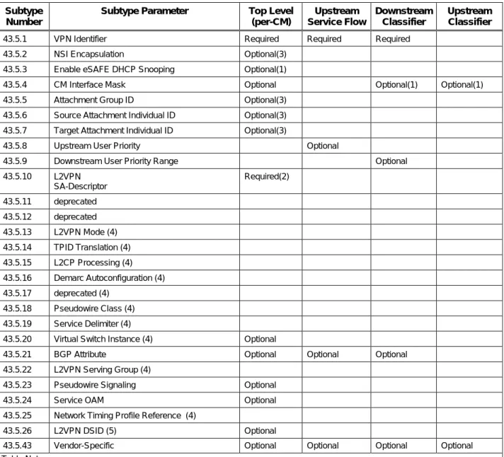
The L2VPN Encoding parameter itself is defined as a multi-part parameter with several nested subtype parameters. The following Table 6–1 lists each of the subtypes and describes in which location the subtype is defined, as required or optional for that location.
Table 6–1 - L2VPN Encoding Subtype Location Summary 20 Subtype
Number
Subtype Parameter Top Level
(per-CM) Upstream Service Flow Downstream Classifier Upstream Classifier
43.5.1 VPN Identifier Required Required Required
43.5.2 NSI Encapsulation Optional(3) 43.5.3 Enable eSAFE DHCP Snooping Optional(1)
43.5.4 CM Interface Mask Optional Optional(1) Optional(1)
43.5.5 Attachment Group ID Optional(3) 43.5.6 Source Attachment Individual ID Optional(3) 43.5.7 Target Attachment Individual ID Optional(3)
43.5.8 Upstream User Priority Optional
43.5.9 Downstream User Priority Range Optional
43.5.10 L2VPN SA-Descriptor Required(2) 43.5.11 deprecated 43.5.12 deprecated 43.5.13 L2VPN Mode (4) 43.5.14 TPID Translation (4) 43.5.15 L2CP Processing (4) 43.5.16 Demarc Autoconfiguration (4) 43.5.17 deprecated (4) 43.5.18 Pseudowire Class (4) 43.5.19 Service Delimiter (4)
43.5.20 Virtual Switch Instance (4) Optional
43.5.21 BGP Attribute Optional Optional Optional
43.5.22 L2VPN Serving Group (4)
43.5.23 Pseudowire Signaling Optional
43.5.24 Service OAM Optional
43.5.25 Network Timing Profile Reference (4)
43.5.26 L2VPN DSID (5) Optional
43.5.43 Vendor-Specific Optional Optional Optional Optional Table Notes:
(1) The CMTS MUST accept a parameter identified as optional (1) in Table 6–1 in a non-forwarding L2VPN Encoding. (2) The CMTS inserts the L2VPN SA-Descriptor Subtype in its first message to a CM in any MAC Management Message that
includes a Forwarding L2VPN Encoding; the L2VPN SA-Descriptor Subtype is not configured in a CM configuration file. (3) This is a Per L2VPN configuration on the NSI port that is defined in a per-CM L2VPN Encoding only for Point-to-Point
forwarding mode.
(4) This TLV is specific to DOCSIS Provisioning of EPON (DPoE) Systems. (5) This TLV is specific to DOCSIS 3.0 and later L2VPN systems
20
If a subtype is not defined as Required or Optional in a location, the CMTS SHOULD silently ignore it when it appears in that location. If a subtype is not defined as Required or Optional in a location, the cable modem
SHOULD silently ignore it when it appears in that location. A CMTS MUST silently ignore unrecognized subtypes in an L2VPN Encoding. A CM MUST silently ignore unrecognized subtypes in an L2VPN Encoding.
The top-level L2VPN Encoding controls the per-L2VPN CM and CMTS behavior specific to a particular L2VPN. The Upstream Service Flow L2VPN Encoding specifies which upstream service flow(s) will carry L2VPN traffic. Proper L2VPN operation requires at least one upstream service flow to be configured for L2VPN forwarding. Because multiple upstream service flows can be configured to forward to the same L2VPN, all of the per-L2VPN parameters common to the L2VPN itself are encoded in the single top-level L2VPN encoding rather than requiring or permitting them to be duplicated in multiple upstream service flow encodings.
Upstream L2VPN forwarding is configured on a per-SF basis. The cable operator can configure at least one
upstream service flow in a CM configuration file with an L2VPN Encoding that defines the VPN Identifier to which the CMTS forwards upstream traffic from that SF. The per-CM or top-level L2VPN encoding is required in a CM configuration file only for point-to-point forwarding mode, in order to define the NSI encapsulation format for that L2VPN so that the CMTS can determine to which CM to forward downstream L2VPN traffic. In point-to-point forwarding mode, a CMTS MUST support one per-CM L2VPN Encoding with an NSI Encapsulation subtype and at least one Upstream Service Flow L2VPN Encoding per CM. With Multipoint forwarding mode for an L2VPN, multiple CMs may forward to multiple NSI encapsulations, so any per-CM NSI encapsulation configuration is not defined.
The simplest CM configuration file for L2VPN operation contains:
• For Multipoint mode, a single per-SF L2VPN Encoding within the primary upstream SF definition; or • For Point-to-Point mode, single per-SF L2VPN Encoding within the primary upstream SF definition and a
single per-CM L2VPN Encoding with an NSI Encapsulation subtype for that L2VPN.
In a Registration Response message, the CMTS always includes a per-CM L2VPN encoding (adding a per-CM L2VPN encoding if necessary) that provides at least one L2VPN SA-Descriptor for encrypting and labeling downstream packets as L2VPN traffic for the CM. The CMTS MAY assign more than one SAID to the same L2VPN, in which case multiple L2VPN SA-Descriptor subtypes may appear in a top-level L2VPN Encoding. Unless configured otherwise, the CMTS delivers downstream L2VPN traffic to a single cable modem on the CM's primary downstream service flow. The operator can specify enhanced Quality of Service (QOS) for downstream L2VPN traffic with a separate downstream service flow for L2VPN forwarding in the CM's configuration file. Downstream L2VPN traffic can be classified to that particular downstream service flow by defining a classifier that includes a Downstream Classifier L2VPN Encoding that references the service flow.
The CMTS MUST reject the registration of a CM with an invalid L2VPN Encoding. A valid CM configuration contains any number of per-SF L2VPN Encodings, Downstream Classifier L2VPN Encodings and Upstream Classifier L2VPN Encodings. The CMTS MUST accept a CM registration request that contains multiple per-SF L2VPN Encodings that forward to the same VPN ID.
A valid per-SF L2VPN Encoding appears as a subtype in the Upstream Service Flow Encoding (type 24) of a DOCSIS 1.1 CM configuration file, REG-REQ, REG-REQ-MP, DSA-REQ, or DSC-REQ message. The per-SF L2VPN Forwarding Encoding configures the CMTS to perform L2VPN bridge forwarding for all CPE packets received in the described service flow. A valid per-SF L2VPN Forwarding Encoding contains one L2VPN ID subtype. The CMTS includes a per-CM L2VPN encoding in its REG-RSP or REG-RSP-MP. After registration, a CM MAY include per-CM L2VPN encodings at the top level of Dynamic Service MAC Managements messages that otherwise add, change, or delete forwarding per-SF L2VPN encodings.
In order to configure particular CPE MAC addresses for L2VPN forwarding, the CM can be configured with Upstream Packet Classification Encodings that match the desired source CPE MAC address. The CM classifies the packet to an upstream service flow that is configured to forward to a particular L2VPN. The Upstream Packet Classification Encoding that references a forwarding Upstream SF L2VPN encoding does not contain a VPNID subtype itself.
The CMTS MUST consider an upstream service flow to be configured for per-SF L2VPN forwarding when a REG-REQ, REG-REQ-MP, DSA-REG-REQ, or DSC-REQ contains exactly one valid per-SF L2VPN Forwarding Encoding within an Upstream Service Flow Encoding. A valid per-SF L2VPN Forwarding Encoding contains one VPNID subtype. The CMTS MUST reject a service flow transaction that contains more than one per-SF L2VPN Encoding. The CMTS MUST accept a valid DSC-REQ with a valid per-SF L2VPN Encoding and change the upstream forwarding treatment of packets received from that SF accordingly. This includes, for example, adding, changing, or deleting any permitted subtype of a per-SF L2VPN encoding, including the VPN ID subtype.
The CMTS MUST remove per-SF L2VPN forwarding for an SF when the SF is deleted with a valid Dynamic Service Delete (DSD) transaction or a Dynamic Service Change (DSC) transaction completes that omits a previously signaled per-SF L2VPN Encoding.
The CMTS MUST support multiple per-SF L2VPN Encodings, each on a separate SF, with the same VPNID Subtype value.
A multipoint forwarding CMTS MAY accept the per-VPN subtypes defined only for point-to-point mode, but CMTS operation with different subtype values on different CMs is not defined.
6.2.1 VPNID Subtype 21
The VPNID Subtype is an opaque byte sequence that identifies a logical Layer 2 Virtual Private Network. All hosts attached to the same logical L2VPN communicate with each other as if they were attached to the same private LAN. An L2VPN is a network that forwards packets based only on layer 2 information such as the Ethernet MAC
addresses and any VLAN ID tags encapsulating the packet. The term VLAN ID should be used only to describe the 12-bit VLAN ID field encoded in an IEEE 802.1Q tag, or IEEE 802.1ad tag pair of an L2VPN packet forwarded on an NSI port.
A cable operator is expected to configure a unique VPNID for each commercial enterprise to which it offers Transparent LAN service. The cable operator may choose any format desired for the VPNID, but it should be globally unique. One suggested approach is [RFC 2685], which defines a mechanism for assigning 7-byte globally unique VPN Ids, based on combining a 3-byte Organization Unique ID for the organization assigning the ID (e.g., the cable operator itself), with a 4-byte VPN ID assigned by that organization. Another suggested approach is [RFC 4364], which describes an 8-byte Route Distinguisher that may be used as a globally-unique VPNID. The CMTS MUST ignore a per-SF L2VPN encoding that omits a VPNID subtype or that contains more than one VPNID subtype. The CMTS MUST support at least four (4) different values of VPNID per CM, signaled in four or more per-SF L2VPN Encodings.
6.2.1.1 BGP VPNID Subtype 22
The BGP VPNID Subtype is a 4-byte integer value that also identifies a logical Layer 2 Virtual Private Network. BGP VPNID Subtype is required only if BGP auto-discovery and LDP signaling [RFC 6074] is to be used by CMTS for L2VPN dynamic discovery.
A cable operator is expected to configure a unique BGP VPNID for each commercial enterprise to which it offers L2VPN service, if the operator intends to use BGP auto-discovery and LDP signaling of pseudowires at the CMTS. A cable operator may configure the same integer value in both VPNID and BGP VPNID Subtypes for operational simplicity. Please see Section 6.2.7.2.2 (BGP Auto-discovery) for more details.
21
Revised per L2VPN-N-10.0918-2 on 5/10/10 by JB.
22