Full Terms & Conditions of access and use can be found at
https://www.tandfonline.com/action/journalInformation?journalCode=taut20
Automatika
Journal for Control, Measurement, Electronics, Computing and
Communications
ISSN: 0005-1144 (Print) 1848-3380 (Online) Journal homepage: https://www.tandfonline.com/loi/taut20
Development of ANFIS-based reference flux
estimator and FGS-tuned speed controller for DTC
of induction motor
S. Sampath Kumar, R. Joseph Xavier & S. Balamurugan
To cite this article: S. Sampath Kumar, R. Joseph Xavier & S. Balamurugan (2018) Development of ANFIS-based reference flux estimator and FGS-tuned speed controller for DTC of induction motor, Automatika, 59:1, 11-23, DOI: 10.1080/00051144.2018.1486796
To link to this article: https://doi.org/10.1080/00051144.2018.1486796
© 2018 The Author(s). Published by Informa UK Limited, trading as Taylor & Francis Group.
Published online: 06 Jul 2018.
Submit your article to this journal
Article views: 307
View related articles
AUTOMATIKA
2018, VOL. 59, NO. 01, 11–23
https://doi.org/10.1080/00051144.2018.1486796
REGULAR PAPER
Development of ANFIS-based reference flux estimator and FGS-tuned speed
controller for DTC of induction motor
S. Sampath Kumara, R. Joseph Xavierband S. Balamurugana
aDepartment of Electrical and Electronics Engineering, Amrita School of Engineering, Coimbatore, India;bSri Ramakrishna Institute of
Technology, Coimbatore, India
ABSTRACT
This paper discusses about self-regulating the reference flux in induction motor (IM) direct torque control (DTC) drive by fuzzy logic. Self-regulation is improved by using “Artificial Neural Network (ANN)” and “Adaptive Network Based Fuzzy Inference System (ANFIS)” based reference flux esti-mators. Furthermore, PI speed controller is investigated to develop the performance of the drive. Two different PI speed controller tuning strategies, manual and Fuzzy Gain Scheduling (FGS), are compared for load torque disturbance. The results clearly show that the modified DTC of IM with “ANFIS-based reference flux estimator and FGS-tuned PI speed controller” is most suitable for torque ripple reduction and speed control.
ARTICLE HISTORY Received 16 August 2017 Accepted 1 June 2018 KEYWORDS
Direct torque control; fuzzy logic;ANN; ANFIS; fuzzy gain scheduling; PI controller
1. Introduction
Induction motors (IMs) are extensively used in industry due to their cost-effectiveness, reliability and robust-ness to load variations [1–5]. The field-oriented con-trol (FOC) is applied to regulate the IM like a DC Motor. FOC became complicated due to the involve-ment of Concordia transformation, current regulator and pulse width modulation signal generator [5]. In the late 1980s, M. Depenbrock, Takahashi and T. Noguchi introduced a new concept of IM mechanism called direct torque control (DTC) [6,7]. It is simple in struc-ture and avoids coordinate transformation and cur-rent regulator. It is robust to the variations of machine parameters. DTC directly controls the torque and sta-tor flux of the IM by adjusting the inverter switching signals. The inverter switching signals are taken from a predefined look-up table. The look-up table was created by the output of the three- and two-level comparators using hysteresis loop, stator flux position [8].
Many researchers have tried to involve artificial intelligence (AI) techniques to modernize the DTC. In DTC, the AI techniques have been applied for generat-ing switchgenerat-ing signals to voltage source inverter. The AI techniques like ANN, fuzzy and neuro-fuzzy can also be applied to hysteresis comparator, reference flux estima-tor and PI speed controller [9–12]. Increasing the sector division in the locus of the flux [13] is also tried.
Control algorithms have been developed by the authors [14,15] for computing the stator flux reference by command torque to reduce the ripples in torque. But these control algorithms are based on mathemat-ical approximations relating the stator flux reference
value and the command torque. The stator flux refer-ence value is computed based on command torque by using fuzzy logic [16]. The estimated flux of stator is named as the modified reference flux. The fuzzy logic controller inputs are error in torque, stator flux refer-ence value and the output is the modified referrefer-ence flux. Still, the stator flux reference value and the modified ref-erence flux membership functions are not distributed symmetrically and continuously. Hence, the solution obtained may not be global.
The speed control of IM with DTC is normally by a PI speed controller [17–18]. A neuro-fuzzy controller (NFC) based on IM speed control is used [19–22] to replace the conventional PI speed controller [23]. NFC uses the benefits of both fuzzy as well as neural net-work. The PI speed controller can be optimized in DTC using adaptive heuristic search algorithms like genetic algorithm (GA) and particle swarm optimiza-tion (PSO) [24–25]. The constant gain values obtained may not provide optimum for all changes in system conditions. Adjusting the PI speed controller gain val-ues by an adaptive mechanism for fuzzy inference is presented as Fuzzy Gain Scheduling (FGS) [26–28]. The adaptation is based on error in speed and deriva-tive of error in speed. The error in speed and derivaderiva-tive of error in speed membership functions were divided into seven membership functions but the output has only two membership functions. This yields almost the same values of controller gain even for large changes in speed error [26–27]. Hence, the fine-tuned controller gain values are not obtained. The reference flux value is not modified according to loading conditions by the
CONTACT S. Balamurugan s_bala_eee@rediffmail.com Department of Electrical and Electronics Engineering, Amrita School of Engineering, Coimbatore, India
© 2018 The Author(s). Published by Informa UK Limited, trading as Taylor & Francis Group.
This is an Open Access article distributed under the terms of the Creative Commons Attribution License (http://creativecommons.org/licenses/by/4.0/), which permits unrestricted use, distribution, and reproduction in any medium, provided the original work is properly cited.
researchers [20–27], whereas it is maintained constant from no load to full load.
In this research work, the major contributions are as follows
• Fuzzy-based reference flux estimator is proposed for DTC with suitable symmetrical membership func-tions in the inputs and output.
• ANN and ANFIS-based reference flux estimators are developed for DTC. These ANN and ANFIS-based reference flux estimators are attempted which have not been tried by other researchers so far.
• The adaptive Fuzzy Gain Scheduled PI controller is proposed for the reference torque estimator (Speed PI controller) in DTC. This overcomes the disad-vantage of yielding same gain values even for large changes in speed.
2. Modelling of induction machine and DTC strategy
The basic theory of DTC, shown in Figure1, is to con-trol directly the stator flux and electromagnetic torque of IM. This is done by applying the suitable voltage vector from the inverter to the motor. The voltage vectors are designated from a standard look-up table (Table1). The voltage vector rotates the stator flux and produces the required electromagnetic torque in the IM [1]. During this operation, stator flux and electromag-netic torque magnitude of the motor are confined using a predefined hysteresis band. The stationary reference frame modelling of IM is done by converting the three-phase quantities (Va,VbandVc) into two-phase, dq-axis quantities (Vds,Vqs) using Clarke’s transformation [2–5].
The induction machine [4,5], dynamic machine model developed in stationary reference frame, establishes
Table 1.Look-up table for DTC.
ds dTe α(1) α(2) α(3) α(4) α(5) α(6) 1 1 V2 V3 V4 V5 V6 V1 1 0 V0 V7 V0 V7 V0 V7 1 −1 V6 V1 V2 V3 V4 V5 0 1 V3 V4 V5 V6 V1 V2 0 0 V7 V0 V7 V0 V7 V0 0 −1 V5 V6 V1 V2 V3 V4
the relation between voltages and currents in matrix form using equivalent circuit of induction machine as
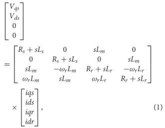
⎡ ⎢ ⎢ ⎣ Vqs Vds 0 0 ⎤ ⎥ ⎥ ⎦ = ⎡ ⎢ ⎢ ⎣ Rs+sLs 0 sLm 0 0 Rs+sLs 0 sLm sLm −ωrLm Rr+sLr −ωrLr ωrLm sLm ωrLr Rr+sLr ⎤ ⎥ ⎥ ⎦ × ⎡ ⎢ ⎢ ⎣ iqs ids iqr idr ⎤ ⎥ ⎥ ⎦, (1)
wheresis the Laplacian operator.VdsandVqs are the stator dq-axis voltage components. The stator and rotor resistances are referred asRsandRrrespectively. Stator, rotor and mutual inductances are referred asLs,Lrand
Lm, respectively. By using Equation (1), the stator and rotor current components for dq-axisids,iqs,idrandiqr can be calculated. The corresponding flux components
ds,qs,drandqrare given by Equations (2) to (5) [5].
ds =
(Vds−idsRs)dt, (2)
AUTOMATIKA 13
Figure 2.Proposed structure of DTC for performance improvement.
qs= (Vqs−iqsRs)dt, (3) dr = − (qrωr+idrRr)dt, (4) qr= (drωr−iqrRr)dt. (5) The actual torque (Te), stator flux (s), stator flux angle (α) and actual speed (ωr) are developed using Equations (6) to (9) [5]. The torque component is esti-mated from Te= 3 2 ∗P 2 ∗ (dsiqs−qsids). (6) The IM actual speed (ωr) in Figure 1is calculated using ωr = 1 J (Te−TL)dt, (7) whereTLis load torque andJrepresents the inertia.
For the stator flux (s),
s= (ds2 +2
qs). (8) The calculated stator flux angle (α) is given by (9),
α=tan−1 qs ds . (9)
The reference torque (T*) is calculated by PI speed controller with input as speed error (ω∗−ωr). The difference between reference torque (T*) and actual electromagnetic torque (Te) is obtained from Equation (6) and applied to the three-level torque comparator in Figure1[5–7]. Sector number is calculated by using the stator flux angle (α) [5]. The angle of stator flux (α) is separated into six sectors as−30° to 30° as sec-tor 1, 30° to 90° as secsec-tor 2 and similarly till secsec-tor 6 as
−90° to−30°.
The DTC controls the triggering signals to the volt-age source inverter by the outputs from the three-level torque hysteresis comparator (dTe), two-level flux hys-teresis comparator (dψs) and sector estimator. Based on the output, the triggering signals to the voltage source inverter are selected from a standard look-up table [5]. Due to the hysteresis comparators, the triggering sig-nals not only depend on the amplitude but also on the direction of flux and torque. In this paper, soft com-puting techniques are applied to reference flux estima-tor and PI speed controller for better performance of DTC. The usual reference flux estimator is replaced by fuzzy,ANN- and ANFIS-based reference flux estima-tors. The PI speed controller is tuned using manual and FGS methods. Thus, by using soft computing methods, modified reference flux estimator and PI speed con-troller are established as shown in Figure2for DTC of IM.
3. Reference flux estimator
In general, IMs are always operated at rated flux to meet the maximum load torque and also during starting con-ditions. According to Equations (2) and (3), the stator flux value will change proportional to voltage vector applied.
3.1. Fixed reference flux estimator
Normally for DTC, the reference flux is estimated from the reference flux estimator in Figure1. From the IM characteristics [2] for flux, it is perceived that the motor speed upto rated value operates in constant flux region. Hence, the reference flux estimator shown in Figure1
gives constant reference flux till the rated speed and after that it transfers to field weakening region. Oper-ating the motor always at constant reference flux is not
Figure 3.Fuzzy/ANN/ANFIS-based reference flux estimator.
a suitable idea especially under light load and no load conditions.
In light load conditions, constant flux causes more core loss and poor efficiency [14]. In DTC, the ampli-tude of flux in terms of torque is generally given as
ψs
ψsn =
Te
Ten. (10)
The above equation is simple but it does not include the power dissipation of the drive.
3.2. Fuzzy-based reference flux estimator
The torque ripple is minimized by optimizing the ref-erence flux estimator using fuzzy logic controller as shown in Figure3. The inputs to the fuzzy logic con-troller are [16] torque error (T*−Te) and the reference flux (∗) from the reference flux estimator. The output is the correction in reference flux (ψ∗) required for modified reference flux (ψm∗).
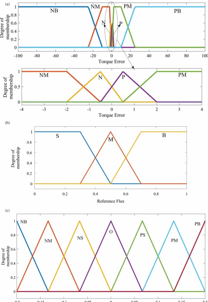
The FLC membership functions for both input and output are presented in Figures4(a–c), respectively.
The response of the torque error (T*−Te) of the system, when tried with three membership functions, is very slow. The slow response in three membership functions-based fuzzy is due to the wide range of torque error (T*−Te). This keeps the slope of the membership functions smaller and therefore the system response is very slow. To overcome this issue, in this paper, six membership functions-based fuzzy is used. The torque error variation (T*−Te) during starting, load changes and steady state vary between [−100, 100], [−28, 28] and [−3, 3], respectively. Due to this reason, the bership functions are not regular. Though the mem-bership functions are not regular, the total degree of membership functions for any input value over the uni-verse is one (i.e. symmetrical membership functions are maintained). Since the range for torque error (T*−Te) during starting, load changes and steady state are not in uniform pattern and regular placement of membership functions cannot be used.
The computation inside fuzzy for a three-member ship will be faster than six-membership functions, but it fails to provide required control on all the three stages namely starting, load changes and steady state.
When the number of membership functions is more than six, a large change in output is observed for small change in input. Hence for stable performance, torque error (T*−Te) and reference flux from refer-ence flux estimator (∗) are divided into six and three fuzzy subsets with linguistic values{NB=negative big, NM=negative medium, N=negative, P=positive, PM=positive medium, PB= positive big}and{S = small, M=medium, B=big}, respectively.
The universe of torque error (T*−Te) and refer-ence flux (∗) are [−100, 100] and [0, 1], and these ranges are decided by system conditions. The fuzzy inference output is correction in reference flux (ψ∗), which is divided into seven fuzzy subsets with linguistic values {NB=negative big, NM=negative medium, NS=negative small, O=zero, PS=positive small, PM=positive medium, PB=positive big}with uni-verse [−0.2, 0.2]. Since the actual ranges are used in inputs and output, no scaling factor is used before fuzzi-fication and after de-fuzzifuzzi-fication. By using knowledge base, the fuzzy rules are developed. The fuzzy rules used are given in Table2and∗is decided by fuzzy inference [15–16].
The triangular and trapezoidal membership func-tions are chosen for computational simplicity and easy overlapping. The solution offered by symmetrical membership functions is globally applicable, not local.
3.3. ANN-based reference flux estimator
The fuzzy logic-based reference flux estimator provides better response than the conventional reference flux estimator. For further improvement, ANN-based refer-ence flux estimator is developed by collecting data from Fuzzy-based reference flux estimator and trained using backpropagation algorithm.
AUTOMATIKA 15
Figure 4.(a) Input membership functions for torque error. (b) Input membership functions of reference flux. (c). Output membership functions for correction in reference flux.
Table 2.Rule base for∗. ∗ (T∗−Te) NB NM NS PS PM PB S O PM PB O PM PB M NS O PS NS PM PS B NB NM O NB NM O
Like Fuzzy, the proposed ANN has two inputs and single output. The inputs are torque error (T*−Te) and reference flux (∗∗). The output is correction in ref-erence flux (∗). Totally 33,408 input–output data are collected for supervised learning. The backpropagation algorithm provides desired convergence characteristics with required goal for a two-layer architecture with 10 neurons in hidden layer. Log-sigmoid and tan-sigmoid activation functions are used for the hidden and output layers, respectively. The Fuzzy-based reference flux esti-mator explained in Section 3.2 is replaced by the trained ANN to test its performance.
3.4. ANFIS-based reference flux estimator
ANFIS provides training of data based on a suitable mixture of ANN and fuzzy logic. Since the fuzzy logic is not completely adaptive, to optimize the response, the membership functions and the rule base of the fuzzy logic have to be tuned. This requires a tedious trial and error procedure. Therefore, fuzzy logic may not be enough to give proper results. The initial structure of ANFIS is built by knowledge base from fuzzy logic and then that structure is improved by neural network. The five-layer ANFIS structure performs normalization of inputs, fuzzification, rule base evaluation and de-fuzzification. It provides a transparent model, in which a neural network is used to design a fuzzy inference system.
Hence, if the input–output data, input membership functions and rule base are available for a fuzzy system, then neural network training can be used for the adjust-ment of membership functions and rule base. Due to this transparency, the effects of various weight values with torque error (T*−Te) and reference flux (∗∗) are used to find optimal weights for minimal torque error. ANFIS makes an intelligent choice of antecedent and consequent parameters for torque error (T*−Te) and reference flux (∗∗) membership functions. The adaptive nature of ANFIS incorporates various param-eters over a wide range of operating conditions. There-fore, in this paper, the hybrid formulation of Fuzzy and ANN as ANFIS is used to get better system response when compared to fuzzy and ANN alone [19]. ANFIS structure with the Sugeno model is trained with 18 rules. Here, ANFIS provides reference flux to the DTC as given in Figure3. It is clearly shown that the modified reference flux (ψm∗) is computed based on torque error (T*−Te) and the flux from reference flux estimator (∗) by using ANFIS.
ANFIS structure is composed of a five-layer feed forward neural network as in Figure 5. The gradi-ent descgradi-ent and least squares estimator [19] are com-bined in the proposed network. The structure consists of functional blocks as rule base, database, decision-making unit, an interface for fuzzification and a de-fuzzification interface by using five network layers [20–22]. The proposed ANFIS has two variable inputs namely torque error (T*−Te) and the reference flux (∗) from reference flux estimator. The output of the ANFIS is the correction required in reference flux (∗). In the first layer, (T*−Te) and (∗) are mul-tiplied by the corresponding weights and are mapped using membership functions [12]. The second layer is for estimating the input weights for minimum error with firing strength of the rules as,
μi =min(μiA1(T∗−Te),μiA2(ψ∗)), (11)
where μiA1(T∗−Te) and μiA2(ψ∗) are the degree of membership function for torque error and reference flux, respectively. The third layer is for normalization of weights. The normalized value of firing strength is given as
μi= μμi
i. (12)
The fourth layer is for de-fuzzification. The rela-tionship between the input membership functions
{μi
A1(T∗−Te),μiA2(ψ∗)}and the output (O4) can be
defined as,
O4=μ(fi)=μ(pix+qiy+ri), (13) wherepi,qiandriare the node consequent parameters andx=μiA1(T∗−Te)andy=μiA2(ψ∗)are inputs.
The fifth layer is the weighted output summation of layer 4. The output layer is given as
O5= i μifi= i μifi i μi . (14)
ANFIS is developed by collecting 10,004 data from the fuzzy-based reference flux estimator in this work. Initially, the same membership functions from Figure4(a,b) are given as input membership functions for ANFIS. The data are loaded in the ANFIS editor and the structure shown in Figure5is created.
No clustering methods are used during training of ANFIS. Instead of clustering method, grid partitioning method is used for training the ANFIS. The number of nodes is determined based on fuzzy-based reference flux estimator. The network is trained for 100 epochs in the backpropagation algorithm. Then the trained ANFIS is loaded in the system and tested. Membership functions of the universe of torque error (T*−Te) and reference flux (∗) are self-tuned to provide the better performance.
AUTOMATIKA 17
Figure 5.Proposed ANFIS structure. 4. Tuning of PI controller
In DTC, the torque reference is calculated from the speed PI controller as shown in Figure 1. The speed PI controller gain values tuned manually by trial and error method are of fixed values. The values are neither optimum nor adaptive. Hence, fuzzy logic is applied to schedule the PI speed controller gain values adaptively.
4.1. Manual tuned PI speed controller
In manual tuning, the proportional gainKpis acting as a multiplying factor with speed error (ω*−ωr). If the gain value is large, the actual speed (ωr) of the sys-tem will reach the reference speed (ω*) closely. But for larger values of proportional gain, the oscillations are more. The speed PI controller integral part deter-mines the error under the curve. Hence, the integral part of PI speed controller is eliminated using the steady state error. Initially,Kiis made equal to zero and Kp
value is increased till the actual speed (ωr) oscillates like quarter-amplitude decay around the reference speed (ω*). Then,Kiis increased meticulously to adjust the steady state error (23). TheKpandKivalues are fine-tuned together to get optimum response. The system is subjected to step load disturbance for tuning.
4.2. Fuzzy gain scheduling for speed PI controller
The continuous changes in system parameters and the non-linear effective circumstances make the PI speed
controller with fixed gain values incapable of offering essential control. The fuzzy logic approach is capable of handling the changes in parameter and mathemati-cal models are not counted [26–27]. The block diagram of the FGS is given in Figure6. FGS control schemes offer interpolation between the tuning tables based on the instantaneous system conditions.
Equations (15) and (16) give the mathematical con-cept of FGS, whereKp1 andKi1 are the adaptive gain values, which are varying as per the system condition.
Kp1=((ω∗−ωr)·KPFGS), (15)
Ki1=((ω∗−ωr)·KIFGS). (16)
KPFGS andKIFGS are the gain values suggested by FGS. The inputs to the FGS are error in speed (ω*−ωr) and derivative of error in speed (ω*−ωr)’. The uni-verse of discourse of speed error is normalized from 0 to 1 and derivative of error in speed is normalized from
−1 to 1. The normalization is performed in FGS using scaling factor as the largest value and no scaling factor for the output. The number of fuzzy sets used for speed error as well as time derivative of speed error is seven. The (ω*−ωr) and (ω*−ωr)’ are fuzzified using trian-gular and trapezoidal membership functions as shown in Figure7. Linguistic variables of the input and out-put membership functions are VVL=Very very low, VL= very low, L=low, M=medium, H=High, VH=very high and VVH=Very very high. The rule base is given in Table3[28]. The output range for the
Table 3.Rule base for Kp,Ki. (ω*−ωr) KPFGS,KIFGS VVL VL L M H VH VVH (ω*−ωr)’ VVL VVH VVH VVH VH VH H M VL VVH VH VH VH H M L L VVH VH H H M L VL M VH VH H M L VL VL H VH H M L L VL VVL VH H M L VL VL VL VVL VVH M L VL VL VVL VVL VVL
proportional gain is from 0 to 80 and for integral gain is from 0 to 0.75.
5. Simulation results
The conventional DTC scheme given in Figure 1 is established in MATLAB/Simulink® environment. The developed scheme is computer-generated with a 2.2 kW IM. The parameters of the IM are given in the Appendix. The starting of the motor is with no load to a reference speed of 149.67 rad/s from t= 0 s to
t=0.5 s. The effect of load disturbance is observed with a sudden load of 3.65 Nm applied at 0.5 s to the motor and then another step load of 10.95 Nm applied at 1.0 s. After that, at 1.5 s, 7.3 Nm load is removed from the motor. The timing diagram for load variations are chosen based on Uddin [20] and Hafeez [21]. Uddin has analysed the system for 1.0 s with 3 HP machine and
Hafeez has simulated for 0.7 s with 50–75% load varia-tion at 0.3 s. The performance of the DTC is upgraded in the following five control strategies, as shown in Figure2.
• Conventional DTC with fixed reference flux estima-tor and manual tuned speed PI controller (Fixed-Manual).
• Modified DTC with fuzzy-based reference flux esti-mator and manual tuned speed PI controller (Fuzzy-Manual).
• Modified DTC with ANN-based reference flux esti-mator and manual tuned speed PI controller (ANN-Manual).
• Modified DTC with ANFIS-based reference flux estimator and manual tuned speed PI controller (ANFIS-Manual).
• Modified DTC with ANFIS-based reference flux estimator and FGS-tuned speed PI controller (ANFIS-FGS).
The fixed reference flux value used is 0.8 Wb. The fuzzy-based reference flux estimator explained in Section 3.2 is developed using MATLAB/Simulink® environment by fuzzy logic toolbox with FIS edi-tor. ANN-based reference flux estimator in Section 3.3 is developed using Neural Network/Data Man-ager (nntool). ANFIS-based reference flux estimator explained in Section 3.4 is developed in the same
Figure 6.Block diagram of fuzzy gain scheduling.
AUTOMATIKA 19 Table 4.Tuned values of PI speed controller.
Method Kp Ki
Manual 100 0.1
environment using ANFIS editor. When ANN-based reference flux estimator is compared with ANFIS-based reference flux estimator, ANFIS outperforms the ANN-based reference flux estimator.
The PI speed controller is tuned manually by trial and error method as given in Section 4.1, and the gain values are shown in Table4.
The gain values given in Table4are fixed. In order to make the controller to be adaptive for the system condition variations, an FGS-tuned PI speed controller is proposed in Section 4.2. FGS gives variable gain PI speed controller in order to be robust against parameter variations and load disturbances.
5.1. Speed response
The DTC drive has started under no load condition for a reference speed of 149.67 rad/s tillt= 0.5 s. Figure8
shows the speed response of different control strategies for load disturbance. Figure8(a–c) show the zoom-in view during adding and removal of loads. The com-bined response for all the control strategies is shown in Figure8(d). The responses show that the conventional DTC with fixed reference flux estimator and modified DTC with fuzzy-based reference flux estimator perform slowly to overcome the disturbance rejection. However, the “modified DTC with ANFIS-based reference flux estimator and FGS-tuned PI speed controller” performs with quick load disturbance rejection than the other control strategies. Though load disturbance rejection is fast, still there is a small steady state error even in ANFIS-based control strategy.
The speed response of DTC IM during starting and loading conditions are analysed. Figure 9 shows the speed response of five control strategies for load
variations. In Figure9, the fixed reference flux estimator has low settling time during no load whereas the fuzzy,
ANN and ANFIS take some time to adapt to system conditions. After that (0.32 s), for all other load vari-ations, the ANFIS performs better for transient as well as steady-state conditions than fixed and fuzzy control strategies. This is validated using performance indices. The starting speed responses alone are given in Figure 10 from t=0.15 s to t=0.4 s. The “conven-tional DTC with fixed reference flux estimator” and “modified DTC with fuzzy-based reference flux esti-mator” reach reference speed faster than the other two ANFIS-based control strategies. The “modified DTC with ANN-based reference flux estimator” reaches the reference speed slower than all the control strategies.
5.2. Torque response
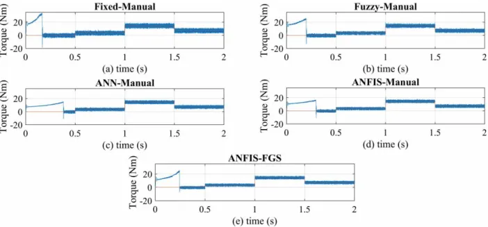
The torque response characteristics for no load, load disturbance and steady state of DTC drive are given in Figure11. The transient period of ANFIS-based con-trol strategies is slightly larger than fixed and fuzzy-based control strategies. The transient response of ANN-based control strategy is poor than ANFIS con-trol strategy. The similar behaviour is observed for speed response also as discussed earlier and shown in Figure10.
The ANN- and ANFIS-based control strategies reach the reference torque with less ripples than fixed and fuzzy-based control strategies. However, when ANN and ANFIS are compared, ANFIS provides better performance. It is clearly shown in Figure11that the “modified DTC with ANFIS-based reference flux esti-mator and FGS-tuned PI speed controller” reduces the torque ripple than other control strategies.
5.3. Flux response
The reference flux is maintained at 0.8 Wb from no load to full load in conventional DTC with fixed reference
Figure 9.Speed responses of all the control strategies.
Figure 10.Starting speed responses of all the control strategies.
AUTOMATIKA 21
Figure 12.Flux responses of all the control strategies.
flux estimator and manual tuned PI speed controller. The reference flux value should change according to loading conditions. The flux responses of DTC with respect to load variations for all the control strategies is given in Figure12.
In fuzzy-based reference flux estimator, the reference flux values are changed using fuzzy logic with respect to loading conditions. The torque error is taken as an objective function and for reducing it, the flux value is varied in consecutive steps. The actual flux changes from its initial value to final value. The flux optimizes the transient level and steady state. The transient level means the speed of convergence and steady state means ripple.
5.4. Performance indices
The performance of speed, torque and flux responses are computed using the performance index Integral Square Error (ISE), Integral time absolute error (ITAE) and Integral time square error (ITSE) using Equations (17), (18) and (19). In these equations, thee(t) stands for error in speed, torque and flux. Control systems specified to minimize ISE will tend to eliminate the large errors quickly. For both transient and steady state,
ISEis valid.
Hence, overshoot and rise time are taken into account while evaluating the performance using the performance indexISE. The performance indices are
Table 5.Performance indices for various reference flux estimators and speed controllers.
ISE ITAE ITSE
Time Torque Flux Speed Total Torque Flux Speed Total Torque Flux Speed Total Fixed-Manual 0.5–1 s 3.964 0.000301 0.001038 3.965339 2.963 0.000227 0.000778 2.964004 0.8489 0.008195 0.01668 0.873775 1–1.5 s 9.632 5.66E−05 0.01387 9.645927 11.41 7.06E−05 0.01728 11.42735 2.128 0.004977 0.1032 2.236177 1.5–2 s 5.384 6.81E−05 0.003642 5.38771 9.432 0.000119 0.000638 9.432757 2.349 0.008024 0.07398 2.431004 Total 18.98 0.000426 0.01855 18.99898 23.805 0.000416 0.018695 23.82411 5.3259 0.021196 0.19386 5.540956 Fuzzy-Manual 0.5–1 s 1.532 0.003076 0.000568 1.535644 1.141 0.002317 0.000425 1.143742 0.5064 0.02102 0.01241 0.53983 1–1.5 s 3.016 1.99E−03 0.0109 3.028893 3.638 2.50E−03 0.0136 3.654103 1.183 0.02756 0.09195 1.30251 1.5–2 s 2.129 2.46E−03 0.002851 2.134308 3.725 0.004309 0.004516 3.733825 1.433 0.04434 0.06253 1.53987 Total 6.677 0.007526 0.014319 6.698845 8.504 0.009129 0.018541 8.53167 3.1224 0.09292 0.16689 3.38221 ANN-Manual 0.5–1 s 1.166 0.000257 0.000141 1.166398 0.8658 0.000193 0.000105 0.866099 0.4475 0.00738 0.006042 0.460922 1–1.5 s 2.107 6.42E−05 0.008346 2.11541 2.587 8.03E−05 0.01042 2.5975 0.9858 0.005674 0.08053 1.072004 1.5–2 s 1.477 6.50E−05 0.001428 1.478493 2.581 1.14E−04 0.002498 2.583612 1.178 0.00786 0.04645 1.23231 Total 4.75 0.000386 0.009915 4.760301 6.0338 0.000388 0.013023 6.047211 2.6113 0.020914 0.133022 2.765236 ANFIS-Manual 0.5–1 s 0.8345 0.000276 0.000248 0.835024 0.628 0.000206 0.000187 0.628393 0.3745 0.00775 0.008231 0.390481 1–1.5 s 1.92 6.52E−05 0.009078 1.929143 2.274 8.10E−05 0.01132 2.285401 0.8452 0.005598 0.08387 0.934668 1.5–2 s 1.209 6.80E−05 0.001777 1.210845 2.113 0.000119 0.003108 2.116227 1.04 0.008081 0.0519 1.099981 Total 3.9635 0.000409 0.011103 3.975013 5.015 0.000406 0.014615 5.030021 2.2597 0.021429 0.144001 2.42513 ANFIS-FGS 0.5–1 s 0.7123 0.000325 0.001467 0.714092 0.5326 0.000246 0.001099 0.533945 0.3434 0.008428 0.02024 0.372068 1–1.5 s 1.101 7.09E−05 0.006545 1.107616 1.363 8.86E−05 0.008136 1.371225 0.7018 0.0059 0.07084 0.77854 1.5–2 s 0.9513 6.96E−05 2.06E−05 0.95139 1.664 0.000122 3.57E−05 1.664157 0.9281 0.000806 3.57E−05 0.928942 Total 2.7646 0.000465 0.008033 2.773098 3.5596 0.000456 0.009271 3.569327 1.9733 0.015134 0.091116 2.07955
Figure 13.Performance indices of torque, flux and speed error in DTC. tabulated in Table5. ISE= T 0 e (t)2dt, (17) ITAE= T 0 t|e(t)|dt , (18) ITSE= T 0 te (t)2dt. (19) Table 5 gives the variation of performance index values for speed error, torque error and flux error for five control strategies. The bold values of performance index in Table5show that ANFIS-based reference flux estimator together with FGS-tuned PI speed controller yields minimal conditions for speed error as well as for torque error. The bar chart from Table5forISEalone is given in Figure13.ITAEandITSEwill also be the same likeISE. The proportional reflections could be verified clearly for flux error.
The improvement in speed control and torque ripple reduction is achieved with the reduction of flux for all the five cases. Also in the fuzzy- and ANFIS-based ref-erence flux estimator, the modified refref-erence flux (ψm∗ ) is instantaneous with respect to torque error as well as reference flux from reference flux estimator (∗).
The performance indices clearly show that the “modified DTC with ANFIS-based reference flux esti-mator and FGS-tuned PI speed controller” is the most suitable one for speed control and torque ripple reduc-tion for DTC IM drive.
6. Conclusion
The modified reference value of flux is computed based on torque error and reference flux from usual reference flux estimator. Self-regulation of reference stator flux value is accomplished with the aid of fuzzy-,ANN- and ANFIS-based reference flux estimators. The control of speed for IM in DTC is accomplished using a PI speed controller. The profound assessment between manual
tuning and FGS is performed. The no load and load dis-turbance rejection characteristics of IM are analysed. The performance indices and responses clearly prove that “modified DTC with ANFIS-based reference flux estimator and FGS-tuned PI speed controller” is most suitable for torque ripple reduction and speed control of DTC IM.
Disclosure statement
No potential conflict of interest was reported by the authors.
References
[1] Vas P. Sensor less vector and direct torque control. Lon-don: Oxford University Press;1998.
[2] Krause PC. Analysis of electric machinery. New York: McGraw-Hill;1986.
[3] Park RH. Two-reaction theory of synchronous machines-generalized method of analysis – part 1. AIEE Trans.1929;48:716–727.
[4] Stanley HC. An analysis of induction motor. AIEE Trans.1938(Supplement);57:751–755.
[5] Bose BK. Modern power electronics and AC drives. Delhi: Prentice Hall;2002.
[6] Depenbrock M. Direct self-control (DSC) of inverter-fed induction machine. IEEE Trans Power Electron.
1988;3(4):420–429.
[7] Takahashi NT. A new quick-response and high effi-ciency control strategy of an induction motor. IEEE Trans Ind Appl.1986;IA-22(5):820–827.
[8] Rosic MM, Bebic MZ. Analysis of torque ripple reduc-tion in inducreduc-tion motor DTC drive with multiple volt-age vectors. Adv Elect Comp Eng.2015;15(1):105–114. [9] Toufouti R, Meziane S, Benalla H. Direct torque con-trol for induction motor using intelligent techniques. J Theor Appl Infor Tech.2007;3(3):35–44.
[10] Youb L, Craciunescu A. Direct torque control of induc-tion motors with fuzzy minimizainduc-tion torque ripple. Proceedings of the World Congress on Engineering and Computer Science (WCECS-2009); 2009 October 20–22; San Francisco, CA, USA.
[11] Zidani F, Saud RN. Direct torque control of induction motor with fuzzy minimization torque ripple. J Electr Eng.2005;56(7/8):183–188.
AUTOMATIKA 23
[12] Fayez GA, Amira YH, Reham HM. Adaptive neuro-fuzzy control of induction motor. Ain Shams Eng J.
2010;1(1):71–78.
[13] Prabu T, Sampath Kumar S, Gunabalan R. Advanced direct torque control of induction motor. Proceedings of the International Conference on Process Automation, Control and Computing (PACC-2011); 2011 July 20–22; Tamil Nadu, India.
[14] Kaboli S Z, Haghbin MR, et al. Torque ripple mini-mization in DTC of induction motor based on opti-mized flux value determination). Proceedings of the 29th Annual Conference of IEEE Industrial. Electronics Society (IECON-03); 2003 Nov 2–6.
[15] Li H. Fuzzy DTC for induction motor with opti-mized command stator flux. Proceedings of the 8th World Congress Intelligent Control and Automa-tion (WCICA-2010); 2010 July 7–9; Jinan Shandong, China.
[16] Faith K, Faruk CM, Yilmaz K, et al. Fuzzy based sta-tor flux optimizer design for direct sta-torque control. Int J Instrum Control Syst.2012;2(4):41–49.
[17] Stojic’ D, Millan M, Slavko V, et al. Improved sta-tor flux estimasta-tor for speed sensor less induction motor drives. IEEE Trans Power Electron.2015;30(4): 2363–2371.
[18] Ibrahim MA, Nik Rumzi NI. Simple flux regula-tion for improving state estimaregula-tion at very low and zero speed of a speed sensor less direct torque con-trol of induction motor. IEEE Trans Power Electron.
2016;31(4):3027–3035.
[19] Jyh-Shing RJ. ANFIS: adaptive network based fuzzy inference system. IEEE Trans Syst Man Cybern.1993; 23(3):665–685.
[20] Uddin MN, Wen H. Development of a self-tuned neuro-fuzzy controller for induction motor drives. IEEE Trans Ind Appl.2007;43(4):1108–1116.
[21] Hafeez M, Nasir UM, Rahim NA, et al. Self-tuned NFC and adaptive hysteresis based DTC scheme for IM drive. IEEE Trans Ind Appl.2014;50(2):1410–1420.
[22] Mihai D. Neuro-fuzzy DTC for an electrical drive system with induction motor. A SISO controller for the velocity loop. Ann Univ Craiova Elect Eng Ser.
2013;37:44–51.
[23] Thomas EK. Industrial electronics. New Delhi: PHI Learning Private Ltd;2012.
[24] M’hamed C, Abdel Kader M, Yessema B. Speed con-trol of induction motor using genetic algorithm-based PI controller. Acta Polytechnica Hungarica.
2011;8(6):141–153.
[25] Mohammed MI. Improving the performance of the DTC saturated model of the induction motor in case of two level and three level VSI using GA and PSO algorithms. Int. J. Control Autom Syst. 2012;1(1): 4–11.
[26] Hazzab A, Bousserhane IK, Zerbo M, et al. Real time implementation of fuzzy gain scheduling of PI con-troller for induction motor machine control. Neural Process Lett.2006;24(3):203–215.
[27] Bouserhane IK, Hazzab A, Boucheta A, et al. Opti-mal fuzzy self-tuning of PI controller using genetic algorithm for induction motor speed control. Int J Autom Technol.2008;2(2):85–95.
[28] Chandrakala KRM V, Balamurugan S, Sankara-narayanan K. Variable structure fuzzy gain scheduling based load frequency controller for multi-source multi area hydro thermal system. Int J Electr Power Energy Syst.2013;53:375–381. Appendices Appendix A IM parameters: Rs=3.67 ; Rr=2.32 ; Lm=0.235 H; Ls=0.245 H; Lr=0.248 H;J=0.0126 Kg/m2. Rated values:
Power=2.2 kW; Voltage (V)=400 V; Speed (ω∗)= 149.67 rad/s; Torque (T∗)=14.6 Nm; Poles (P)=4.
Appendix B
List of symbols
Va,VbandVc Supply voltages;
Ia,IbandIc Supply currents;
Vds,Vqs dq-axis components of stator voltages;
V0 to V7 Voltage space vectors from look-up table;
Rs,Rr Resistances of Stator, Rotor;
Ls,LrandLm Inductances of Stator, rotor and mutual
inductance;
ids,iqs,idr
andiqr Stator and rotor current components for
dq-axis;
ds,qs,dr
andqr dq-axis components for stator and rotor
flux;
Te Electromagnetic (Actual) torque;
α Stator flux angle;
Sa, Sb and Sc Switching states from the inverter;
ωr Actual speed of rotor (rad/s);
P Number of poles;
J Inertia constant;
TL Load torque;
μi,μi Firing strength, Normalized value of
fir-ing strength;
μi
A1(T∗−Te)
andμiA2(ψ∗) Degree of membership function for tor que error and reference flux;
fi Input function of the fourth layer;
pi,qiandri Consequent parameters;
xandy Inputs to the fourth layer;
Summation;
O4,O5 Output of the fourth and fifth layer ; n Subscript for nominal quantities; Vdc DC Voltage to the inverter;
Actual Flux;
s Stator Flux;
∗ Reference Flux;
T∗ Reference Torque;
ω∗ Reference Speed;
dTe,dψs Outputs of the torque and flux hysteresis comparators;
ψ∗ Correction in reference flux;
ψ∗
m Modified reference flux;
Kp,Ki Proportional and Integral gain values of PI controller;
(ωr*−ωr)
and (ωr*−ωr)’
Speed error and first derivative of speed error;
Kp1,Ki1 Optimal online tuning gain values.
KPFGSandKIFGS Proportional and integral gain values