Louisiana State University
LSU Digital Commons
LSU Doctoral Dissertations Graduate School
2016
Scheduling and Tuning Kernels for
High-performance on Heterogeneous Processor Systems
Ye Fang
Louisiana State University and Agricultural and Mechanical College, [email protected]
Follow this and additional works at:https://digitalcommons.lsu.edu/gradschool_dissertations
Part of theElectrical and Computer Engineering Commons
This Dissertation is brought to you for free and open access by the Graduate School at LSU Digital Commons. It has been accepted for inclusion in LSU Doctoral Dissertations by an authorized graduate school editor of LSU Digital Commons. For more information, please [email protected].
Recommended Citation
Fang, Ye, "Scheduling and Tuning Kernels for High-performance on Heterogeneous Processor Systems" (2016).LSU Doctoral Dissertations. 4233.
SCHEDULING AND TUNING KERNELS FOR HIGH-PERFORMANCE ON HETEROGENEOUS PROCESSOR SYSTEMS
A Thesis
Submitted to the Graduate Faculty of the Louisiana State University and Agricultural and Mechanical College
in partial fulfillment of the requirements for the degree of
Doctor of Philosophy in
The School of Electrical Engineering and Computer Science
by Ye Fang
M.S., Louisiana State University, 2016 B.S., Shandong University at Weihai, 2009
Acknowledgments
My first and foremost acknowledgment is dedicated to my advisor Prof. J. (Ram) Ramanujam. Ram has always been a great example of a wise and knowledgeable computer scientist. From him, I learned how to elegantly extract models from the real word and resolve them use mathematical tools. Ram provided a great amount of freedom in my research, and encouraged me to access many aspects of the computing community.
I would like to send a big thanks to my co-advisor Prof. Michal Brylinski. Being the sci-ence leader of a bioinformatics high-performance computing project, he gave intense advices on the domain knowledge and taught me the workflows of academic writing. I also want to thank Prof. Mark Jarrel and Juana Moreno, without whom, the Louisiana Alliance for Simulation-Guided Materials Applications (LA-SiGMA) would nots be established. Most of my funding and collaborations should contribute to LA-SiGMA.
Throughout my study at LSU, Dr. Ka-Ming Tam has been a great tutor. He introduced me to numeral computing techniques, which leads to my first project on parallel tempering Monte Carlo simulations for spin glass. I would like to thank Prof. David Koppelman, Prof. Bin Chen, Dr. Zhifeng Yun, Dr. Wei Feinstein and Dr. Jian Tao, for direct instructions on my projects and research. I also sincerely appreciate the help from my closely collaborated colleagues, including Sameer Abu Asal, Mohammad Rastegar Tohid, Yun Ding, Sheng Feng, and Troy Loeffler. Meanwhile, my academic life is incomplete without these friends: Sahar Navaz, Zahra Khatami, Shaoming Chen, Sam Irving, Mengxi Wu, Shayan Shams, etc. I would remain grateful for all their supports.
Many thanks have to be given to my thesis defense committee. Their time, patience, and intellectual contributions have inspired my researches and thesis works. To Prof Michal Brylinski who read through my dissertation proposal in the first place, helped figured out a better way of ranging the sections. The suggestion of using scatter plot instead histogram helped me better understand different visualization techniques. To Prof. Xin Li who suggested the possibility of power capping, defines one of the research topics in
this thesis. To Prof. Gerald Baumgartner, who raised a question regarding the generality of my scheduling algorithms. It triggered me to study distributed resource management systems and their applications. To Prof. Kerry Dooley who kindly shared his wisdom of how end-users are expecting from high-performance computing community.
My parents, Qi Fang and Hong Lei, receive my deepest gratitude and love for their dedication and many years of support. Thank you!
TABLE OF CONTENTS
ACKNOWLEDGMENTS . . . iii
LIST OF TABLES . . . vi
LIST OF FIGURES . . . vii
ABSTRACT . . . xii
CHAPTER 1 INTRODUCTION . . . 1
1.1 THE LANDSCAPE OF HETEROGENEOUS COMPUTING . . . 1
1.2 CHALLENGE I: PERFORMANCE TUNING . . . 3
1.3 CHALLENGE II: PERFORMANCE MODELING AND PREDICTION . . . 3
1.4 CHALLENGE III: SCHEDULING FOR HETEROGE-NEOUS SYSTEMS . . . 4
2 PERFORMANCE TUNING FOR HETEROGENEOUS PROCESSORS . . . . 6
2.1 PROGRAMMING HETEROGENEOUS COMPUTERS . . . 6
2.2 GEAUXDOCK . . . 10 2.3 PERFORMANCE TUNINGS . . . 13 2.3.1 PARALLELIZATION LEVELS . . . 16 2.3.2 DATA STRUCTURE . . . 20 2.3.3 DATA REARRANGEMENT . . . 22 2.3.4 STRENGTH REDUCTION . . . 23 2.3.5 GPU-SPECIFIC TUNING . . . 23 2.4 RESULTS . . . 25
2.4.1 PERFORMANCE WITH AN AMPLE COARSE-GRAINED PARALLELISM . . . 27
2.4.2 PERFORMANCE ON REAL DATA . . . 29
2.4.3 A RELIABLE MODEL FOR THE PERFORMANCE . . . 31
2.4.4 COMPARATIVE BENCHMARKS OF HET-EROGENEOUS PROCESSORS . . . 35
2.4.5 CASE STUDY . . . 36
3 PERFORMANCE MODELING . . . 41
3.1 COARSE GRAINED MODEL . . . 42
3.2 FINE GRAINED MODEL . . . 46
3.3 RESULTS . . . 50
4 TASK SCHEDULING . . . 55
4.1 BACKGROUND . . . 55
4.4 MULTI-SUBJECT RELATIVE RANKING (MRR). . . 60
4.5 AUTOMATIC SMALL TASKS REARRANGING (ASTR) . . . 63
4.6 RESULTS . . . 64
5 OPTIMIZING FOR POWER AND ENERGY . . . 75
5.1 BACKGROUND . . . 75
5.2 POWER-CONSTRAINED TASK SCHEDULING . . . 77
5.3 RESULTS . . . 80
6 CONCLUSION . . . 84
REFERENCES . . . 87
List of Tables
3.1 Optimal values oftiley andtilex, that minimizeR2for the linear
fitting. . . 48
3.2 Comparing the general liner regression fitting score R2 before and after applying the tiling regulation. . . 49
3.3 Fitted parameters of the general linear regression model (Equa-tion 3.6) . . . 49
3.4 The R2 score of the comprehensive performance prediction . . . 54
4.1 The makespans of scheduling 204 tasks on 3 workers. . . 68
4.2 The makespans of scheduling 204 tasks on 30 workers. . . 69
4.3 The makespans of scheduling 176787 tasks on 30 workers. . . 69
4.4 The normalized makespans of scheduling 512 tasks on 16 work-ers. 12 different time matrices are tested. . . 71
4.5 The makespans of scheduling 204 tasks on 3 workers. The es-timated performances of the tasks are not always equal to the actual performance. As a result, the qualities of the schedulings degrade. . . 73
4.6 The makespans of scheduling 176787 tasks on 30 workers. The tasks estimated performances are not always equal to the actual performance. Thereby the qualities of the schedules degrade. . . 74
5.1 Typical power consumptions of heterogeneous processors run-ning GeauxDock. . . 75
List of Figures
2.1 Workflow of virtual screening using GeauxDock. (A) The front-end reads input data and creates a pool of docking tasks. The back-end carries out three consecutive operations: (B) device initialization and data transfer, (C) docking calculations for
in-dividual tasks, and (D) saving output data. . . 14 2.2 Implementation of GeauxDock. (A) The code repository is
di-vided into three modules, a common front-end module for the CPU host and two back-end modules, one for GPU and one for CPU and Xeon Phi. (B) Compiling the source codes produces a series of architecture-specific object files. (C) Linking object
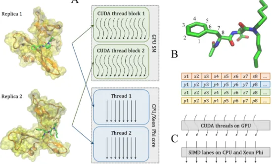
files creates three binary versions for GPU, CPU and Xeon Phi. . . 16 2.3 Two levels of parallelism in the docking kernel. (A) At the
coarse-grained level, individual replicas are assigned to differ-ent CUDA thread blocks on GPU streaming multiprocessors (SMs) and different threads on CPU/Xeon Phi cores. (B) At the fine-gained level, data points for each replica are organized as Structure of Arrays containing Cartesian coordinates x, y, z, and parameters p associated with atoms, such as type, charge, and etc. Parameters for neighboring atoms are placed closely in memory to ensure the best execution efficiency. (C) Data points at the fine-gained level are accessed in parallel by CUDA threads
on GPU and SIMD lanes on CPU and Xeon Phi. . . 19 2.4 Example of parallel calculations for a data matrix. A small,
96-element matrix ligandColumnVector × proteinRowVector is outlined in red, whereas the 4×4 CUDA thread block iterating over the matrix is outlined in blue. Here, at least 6 cycles are required to process the data matrix utilizing a total of 70 paral-lel threads (gray cells), while the remaining 26 threads are idle (white cells). An optimal shape of CUDA thread blocks can be constructed dynamically to improve the computational perfor-mance by reducing the number of cycles required to traverse the
data matrix. . . 20 2.5 Data indexing for multi-replica Monte Carlo simulations.
Indi-vidual replicas are multi-dimensional objects comprising differ-ent combinations of ligand (L) and protein (P) conformations, and temperatures (T), as well as the same set of PSP, KDE, MCS potentials and force field (FF) parameters. All these data are read-only, labeled with tags, and accessible through indexes
2.6 Distribution of various parameters affecting docking time for the dataset of 204 CCDC/Astex compounds. The number of (A) replicas, (B) ligand non-hydrogen atoms, (C) KDE points, and (D) rows in the MCS matrix. KDE (Kernel Density Estimation) and MCS (Maximum Common Substructure) points are used to
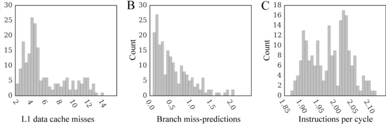
calculate evolution-based components of the docking force field. . . 28 2.7 Performance characteristics for a single-threaded docking kernel
on CPU. The number of (A) level 1 data cache misses per 103
instructions, (B) branch miss-predictions per 103 instructions,
and (C) instructions per cycle. . . 30 2.8 The distribution of speedups of parallel GeauxDock over the
serial CPU version for the dataset of 204 CCDC/Astex com-pounds. Benchmarking calculations are conducted using (A-C, red) modified input data providing an ample coarse-grained par-allelism and (D-F, green) unmodified input data. Three kernel implementations are tested for (A, D) multi-core CPU, (B, E)
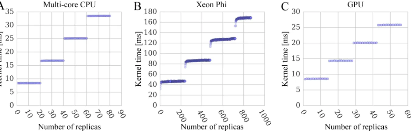
Xeon Phi, and (C, F) GPU. . . 30 2.9 Performance scaling of docking kernels with different numbers
of system replicas. Benchmarking calculations are performed using (A) multi-core CPU, (B) Xeon Phi, and (C) GPU. The width of horizontal lines is 20 replicas for a dual 10-core CPU, 240 for a 60-core Xeon Phi with 4-way multi-threading, and 14
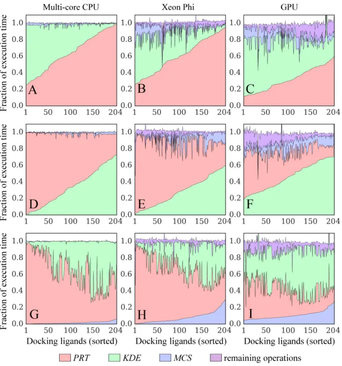
for a 14-multiprocessor GPU. . . 32 2.10 Time breakdowns for docking kernels running on different
plat-forms. Kernel implementations for (A, D, G) multi-core CPU, (B, E, H) Xeon Phi, and (C, F, I) GPU are tested. Three major operations compute the following interaction matrices: protein-ColumnVector × ligandRowVector (PRT, green), KDEColum-nVector × ligandRowVector (KDE, red), and MCSMatrix ×
ligandColumnVector (MCS, blue). Purple areas correspond to the remaining operations. KDE (Kernel Density Estimation) and MCS (Maximum Common Substructure) points are used to calculate evolution-based components of the docking force field, whereas the PRT matrix is used to calculate the majority of physics-based potentials. Results collected for the dataset of 204 CCDC/Astex compounds are sorted on the x-axis with re-spect to increasing time of computing (A, B, C) PRT, (D, E, F)
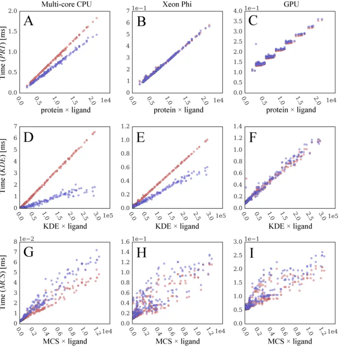
2.11 Correlation between computing time and static data size. Blue points are collected from original GeauxDock, whereas red points correspond to a modified docking code, where dynamic branches are turned off forcing the execution of all instructions. Three major operations compute (A-C) proteinColumnVector × lig-andRowVector (PRT), (D-F) KDEColumnVector× ligandRowVec-tor (KDE), and (G-I) MCSMatrix×ligandColumnVector (MCS) matrices. Three kernel implementations are tested for (A, D, G)
multi-core CPU, (B, E, H) Xeon Phi, and (C, F, I) GPU. . . 39 2.12 Benchmarks of GeauxDock against the dataset of 204 CCDC/Astex
compounds using 6 platforms. Three measures are included, a pure computational performance, the performance divided by the energy consumption, and the performance divided by the hardware cost. Measurements for different platforms are
nor-malized by the performance of Core i7-2600 CPU. . . 40 2.13 Examples of docking calculations using GeauxDock. Three cases
are presented, a peptide ligand and C-src tyrosine kinase ID: 1a07, black), glutathione and glutathione S-transferase (PDB-ID: 1aqw, green), as well as LY178550 and human-thrombin (PDB-ID: 1d4p, red). (A) Solid lines show the pseudo-energy plotted as a function of the accepted Metropolis Monte Carlo (MMC) step; a trajectory of the Contact Mode Score (CMS) is plotted for 1a07 (dashed black line). (B) Scatter plot of the
CMS and pseudo-energy for 1a07. . . 40 3.1 Distribution of relative performance of GeauxDock for the dataset
of 204 CCDC/Astex compounds. Three kernel implementations are tested for multi-core CPU, Xeon Phi and GPU. Relative per-formance between there three platfroms are plotted. (A) Xeon Phi vs. multi-core CPU, (B) Xeon Phi vs. GPU, and (C) GPU
vs. CPU . . . 41 3.2 Coarse gained performance scaling, with computing time as the
Y axis. . . 42 3.3 Coarse gained performance scaling, with computing time divided
by the number of complexes as the Y axis. . . 43 3.4 Defining the performance prediction problem on the coarse level . . . 43 3.5 Using isotonic regression to fit the Xeon Phi performance
3.6 The patterns of GPU performance on P matrix versus different
tile sizes . . . 48 3.7 The patterns of GPU performance onK matrix versus different
tile sizes . . . 49 3.8 The patterns of GPU performance onM matrix versus different
tile sizes . . . 50 3.9 Visualizing the R2 scores under different tilex (x-axis) and tiley
(y-axis) Computing P matrix on CPU. . . 50 3.10 Visualizing the R2 scores under different tile
x (x-axis) and tiley
(y-axis) Computing P matrix on MIC. . . 51 3.11 Visualizing the R2 scores under different tile
x (x-axis) and tiley
(y-axis) Computing P matrix on GPU. . . 51 3.12 Visualizing the R2 scores under different tile
x (x-axis) and tiley
(y-axis) Computing K matrix on CPU. . . 51 3.13 Visualizing the R2 scores under different tilex (x-axis) and tiley
(y-axis) Computing K matrix on MIC. . . 52 3.14 Visualizing the R2 scores under different tile
x (x-axis) and tiley
(y-axis) Computing K matrix on GPU. . . 52 3.15 Visualizing the R2 scores under different tile
x (x-axis) and tiley
(y-axis) Computing M matrix on CPU. . . 52 3.16 Visualizing the R2 scores under different tile
x (x-axis) and tiley
(y-axis) Computing M matrix on MIC. . . 53 3.17 Visualizing the R2 scores under different tilex (x-axis) and tiley
(y-axis) Computing M matrix on GPU. . . 53 3.18 Correlation between the predicted and actual execution time for
(A) multi-core CPU, (B) Xeon Phi, and (C) GPU. . . 54 3.19 The histogram plots show the error of the execution time
pre-diction versus the actual value. The three sub-figures are for
(A) multi-core CPU, (B) Xeon Phi, and (C) GPU. . . 54 4.1 Arranging tasks in priority queues in the ROB algorithm. . . 59 4.2 MRR heuristic 2: the node in red color hold the highest overall
4.3 MRR heuristic 3 and 4: the node in red color holds the lowest
remote rank, and is therefore selected. . . 62 4.4 The scheduling results of using different algorithms. The
exper-iment is carried on 204 tasks on 3 workers. Each of the three horizontal bar is the time slot of of a worker. Each colored clock
is a task. . . 66 5.1 The power statistics of Xeon Phi 7120P running GeauxDock.
The right figure zooms into the beginning of the procedure. . . 77 5.2 The power statistics of Tesla K20m GPU running GeauxDock.
The right figure zooms into the beginning of the procedure. . . 77 5.3 The impact of the performance and energy consumption by
ap-plying different power capping ratios. . . 81 5.4 The comparison of three computer systems running the same
tasks set. All of the computer systems consume the same amount
Abstract
Accelerated parallel computing techniques using devices such as GPUs and Xeon Phis (along with CPUs) have proposed promising solutions of extending the cutting edge of high-performance computer systems. A significant high-performance improvement can be achieved when suitable workloads are handled by the accelerator. Traditional CPUs can handle those workloads not well suited for accelerators. Combination of multiple types of processors in a single computer system is referred to as a heterogeneous system.
This dissertation addresses tuning and scheduling issues in heterogeneous systems. The first section presents work on tuning scientific workloads on three different types of proces-sors: multi-core CPU, Xeon Phi massively parallel processor, and NVIDIA GPU; common tuning methods and platform-specific tuning techniques are presented. Then, analysis is done to demonstrate the performance characteristics of the heterogeneous system on dif-ferent input data. This section of the dissertation is part of the GeauxDock project, which prototyped a few state-of-art bioinformatics algorithms, and delivered a fast molecular docking program.
The second section of this work studies the performance model of the GeauxDock com-puting kernel. Specifically, the work presents an extraction of features from the input data set and the target systems, and then uses various regression models to calculate the perspec-tive computation time. This helps understand why a certain processor is faster for certain sets of tasks. It also provides the essential information for scheduling on heterogeneous systems.
In addition, this dissertation investigates a high-level task scheduling framework for het-erogeneous processor systems in which, the pros and cons of using different hethet-erogeneous processors can complement each other. Thus a higher performance can be achieve on hetero-geneous computing systems. A new scheduling algorithm with four innovations is presented: Ranked Opportunistic Balancing (ROB), Multi-subject Ranking (MR), Multi-subject Rela-tive Ranking (MRR), and Automatic Small Tasks Rearranging (ASTR). The new algorithm
consistently outperforms previously proposed algorithms with better scheduling results, lower computational complexity, and more consistent results over a range of performance prediction errors.
Finally, this work extends the heterogeneous task scheduling algorithm to handle power capping feature. It demonstrates that a power-aware scheduler significantly improves the power efficiencies and saves the energy consumption. This suggests that, in addition to performance benefits, heterogeneous systems may have certain advantages on overall power efficiency.
Chapter 1
Introduction
1.1
THE LANDSCAPE OF HETEROGENEOUS
COM-PUTING
The increasing complexities of scientific models and big data applications demand ex-treme scale of computing power. Parallel high-performance computers (HPC) currently handle these requirements. The TOP500 list is a list released twice a year, which details the 500 most powerful computers in the world. For example, see the 46th HPC TOP500 list released in November 2015 [1, 2]. In that list, the top spot was taken by Tianhe-2 cluster supercomputer; Tianhe-2 has 16,000 compute nodes where each node has 2 “Ivy bridge-EP” Xeon multi-core CPUs as well as 3 “Knights Corner” Xeon Phi co-processors. Tianhe-2 achieves a performance of 33.8 petaFLOPS on the HPL benchmark; but Tianhe-2 uses a lot of energy. As much as 24 megawatts (MW) power (with cooling) is consumed by the whole system. Actually, the number one spot on the TOP500 list has been held by Tianhe-2 for six consecutive times.
The research and practice of building the powerful HPCs faces three main challenges. These challenges come from three directions, which are commonly called three “walls.”
The first wall that blocks the performance progress is the single-core performance ceiling that emerged a decade ago [3]. The researchers can hardly implement higher clock rate through advancing circuit technologies, and have difficulty extracting more performance per clock cycle. This problem was addressed by the advent of the chip multiprocessor (CMP) or multi-core CPUs techniques. The cores of the processor are not designed to grow faster, but to replicate and grow in number. In addition to programmability challenges, contemporary multi-core CPUs suffer a burden from power constraints.
model [4] showed that regardless of chip organization and topology, multi-core scaling is increasingly power-limited. “Even at 22nm, 21% of a chip must be powered off, and at 8nm, this number grows to more than 50%” [4]. Given this scenario, more power-efficient architectures are badly needed.
The desire for power optimization also comes from the economics of energy usage, which is the third wall. Tianhe-2 computer consumes 24 MW power in total, and each megawatt watt of electric power cost approximately 1 million U.S dollar per year [5]. The budget to pay the electric bill is right at the boundary of even the most demanding facilities are willing to afford. The HPC community has long been planning for an exascale computer (1 exaFLOPS = 1000 petaFLOPS) at 30 megawatts power budget. This means the new supercomputer must improve its power efficiency by at least 15 times over the current generation. To achieve this goal, heterogeneous systems with CPUs and accelerators play a major role.
In principle, a heterogeneous accelerator means an attached computing device on top of the traditional CPU and RAM (denoted as host). Unlike a homogeneous system, such as the Symmetric multiprocessing (SMP) or Massively Parallel Processor Array (MPPA), the architectures of accelerators are different from that of the host processor. This implies the programmer cannot freely partition workloads on heterogeneous computers without any performance consequences. nfortunately, no architecture is ultimately efficient for all workloads. To program an accelerated heterogeneous computer system, the programmer must strive to design the optimal partition of the program to maximize the suitability, and at the same time minimize the overheads from data transfers and synchronization. The process of moving a workload from host to accelerator is usually called offloading.
There are two types of heterogeneous accelerators. One is special-purpose hardware. Application-specific integrated circuits (ASICs) are commonly deployed in network and en-cryption applications, and recently have demonstrated successful experience in accelerating neural network modeling [6]. Field-programmable gate arrays (FPGAs) are a lower cost
alternative to ASICs, and have recently been utilized for machine learning [7] and image processing applications [8]. There is on-going research on quantum computing devices [9] that could also be considered as a special kind of heterogeneous computing system. Another type of heterogeneous accelerator is built on the concept of massively parallel processing. In contrast to traditional CPU architectures designed to minimize the execution latency on serial codes, this kind of accelerator features massive amount of highly simplified cores, and are generally optimized for high-throughput computations. Therefore, their performance on latency-sensitive applications is often poor. Consequently, the common programming strategy is to leave control-intensive irregular code on the CPU, and offload highly paral-lel highly regular computations onto these devices for acceleration. This genre of massive parallel accelerator is currently more mature and widely adopted in HPC. In this work, I will exclusive discuss this type of accelerators. Section 2.1 gives background information on their architectures and programming models.
1.2
CHALLENGE I: PERFORMANCE TUNING
The architectures of heterogeneous accelerators require extensive performance tuning, where the combination of tuning techniques remain highly application-specific and is sen-sitive to input data. In the first part of my dissertation, I describe my efforts of tuning multi-core CPUs, Xeon Phi and NVIDIA GPUs, using the newly developed GeauxDock
modular docking software as a case study. I’ll present the performance tuning methodolo-gies and algorithms, as well as a detailed analysis of the performance characteristics.
1.3
CHALLENGE II: PERFORMANCE MODELING
AND PREDICTION
In the second part of this dissertation, I’ll be resolving the performance prediction problem. My work on this leverages machine learning models and the architectures of heterogeneous computers. It helped better understand why a certain task would be favored
on a certain processor.
1.4
CHALLENGE III: SCHEDULING FOR
HETERO-GENEOUS SYSTEMS
Thirdly, programming for contemporary heterogeneous computers relies on the intu-ition of programmers for code decomposintu-itions. Specifically, programmers need to explicitly construct the partition of the code as well the partition of the data. A few research projects try to automate this process. However, some [10, 11, 12, 13, 14] ignore performance het-erogeneity, simply partitioning the data into various sized chunks. Others [15, 16] select only the most suitable heterogeneous processor for work and let the other processors idle all the time. None of them achieve system-wise optimization. My research is based on the view that in order to fully unleash the computational capabilities and maximize efficiency, a good system must consider the heterogeneity of both possessor characteristics and work-load characteristics. Meanwhile, activating more processors is always better if power is not a constraint. Accordingly, I’ll be resolving the following problem: Let there be many independent computational tasks and many heterogeneous processors. Assuming each task could run on any processor, how does one minimize the overall computation wall time? In section 4, I propose a scheduling algorithm to optimize the computational throughput. Additionally, in section 5, I study power and energy as additional metrics. The scheduling algorithm is also extended to optimize for power efficiency.
Chapter 2
Performance Tuning For
Heterogeneous Processors
2.1
PROGRAMMING HETEROGENEOUS
COMPUT-ERS
A CPU core is a fully functional module that could execute one instruction streams at a time. Traditional CPU has one core, whereas, multi-core CPUs systematically integrate more than one cores and therefore simultaneously support multiple instruction streams. Modern CPU cores deploy both Single Instruction Single Data (SISD) [17] computation model and Single Instruction Multiple Data (SIMD) [17] computation mode. Thus a core is able to operate on scalar data or vector data. Intel “Ivy Bridge” Xeon E5 2680 v2 is an example of modern multi-core CPU. It has 10 cores, each core features two 256bit wide SIMD unites. On every cycle, it could compute one 256 bit AVX addition instruction coupled with one 256 bit AVX multiplication instruction.
GPUs evolve from the dedicated hardware to accelerate graphics processing Applica-tion Programming Interfaces (APIs) like OpenGL [18] and DirectX [19]. GPUs use many vector operations and offer up to hundreds of times more raw computation power than con-temporary CPUs. The result is that GPU has been redirected from graphics processing to general-purpose computations. The community use the terminology “GPGPU computing” to describe this kind of practice in the early day when re-targeting graphics oriented APIs. In the current era, numerous languages (such as CUDA, OpenCL), libraries and tools are specifically built for this purpose; as a result, the term “GPU programming” is used to describe this activity.
Many Integrated Core (MIC) is the initial result of Intel’s effort in pushing its x86 architecture for graphics computing. Their effort later adapted towards the HPC market,
with the feature set quite similar to traditional CPUs. The Intel Xeon Phi is the band name of Intel’s MIC offering.
Heterogeneous computing is a major player in today’s HPC community, and is cur-rently dominated by two vendors: NVIDIA GPU and Intel Xeon Phi. These two offerings share some common features, but also have unique characteristics. With respect to hard-ware, both accelerators as well as contemporary multi-core CPUs share a two-level parallel architecture principle. The coarse-grained outer level constructs a computation cluster whose processing elements provide the fine-grained inner level of parallelism. For example, from the perspective of GPU computing, the GPU can be viewed as a cluster of vector pro-cessors. Each GPU contains an array of Streaming Multiprocessors (SMs), each of which consists of many Scalar Processors (SPs), transcendental function units, registers, and fast on-chip memory. I can closely match GPU’s hierarchical architecture model to that of the multi-core CPU. Just as the core is the building block unit of a CPU, a SM is a building block of a GPU. Similar to the lanes in a CPU core’s SIMD unit, SPs are SM’s vector lanes. With regard to software, each coarse-grained cluster handles its own programming con-text known as a thread on CPU and Xeon Phi, and a thread block defined by the GPU Compute Unified Device Architecture (CUDA) [20] paradigm. On the CPU and Xeon Phi, the inner level exposes data parallelism, viz. SIMD operations. NVIDIA GPU uses CUDA threads inheriting a similar principle of vector processing. For instance, a bundle of 32 consecutive CUDA threads, denoted as a warp, are scheduled together. Consequently, CUDA threads may go to predication when a small, conditionally protected piece of code is encountered, forcing the execution of all instructions. When different CUDA threads take different paths in multiple-path branches, more cycles are consumed leading to a lower device utilization. Although SIMD instructions on CPU and Xeon Phi have similar char-acteristics, the vector width is about one-quarter to one-half of that on GPU and the code generation heuristic can vary significantly. Therefore, irregular codes may perform dra-matically differently on these platforms. Another major difference between CPU and Xeon
Phi, and GPU is that the former implement hardware multi-threading at the outer level, whereas multi-threading on GPU is at the inner level demanding more data parallelism. Comparing Xeon Phi with CPU, it delivers roughly equal amount of raw compute power per core in terms of the number of data operations per cycle. However, because of a larger number of computing cores, Xeon Phi offers certain advantages over CPU in processing regular, highly parallel workloads. On the other hand, CPU cores typically perform better for irregular workloads.
In addition, the compute performance is also affected by memory operations. CPU and Xeon Phi heavily rely on caches that enforce coherence, and are easy to program. Since cache implementations are costly, they are hard to scale and can lead to low performance. On the other hand, GPUs expose their fast on-chip memory to programmers, known as the CUDA shared memory. This design makes life harder for programmers. But if done right, it could be highly efficient.
Parallel programming models fall into two broad categories: 1) small groups of tightly coupled processors sharing a common memory space, and 2) large, scalable systems that do not share a common memory. Both models often coexist in a high-performance computing (HPC) environment; for instance, many HPC systems use the distributed memory model to scale up to thousands of multi-processor nodes, each employing the shared memory model. Common programming practices to program multi-core CPU in the shared memory systems are to use libraries or parallel programming languages (extensions) or compiler pragmas. Examples are Pthreads [21], TBB [22], HPX [23], Boost::thread [24]. OpenMP [25]. In contrast, distributed memory systems require manually implemented message-passing procedures, e.g., using Message Passing Interface (MPI) protocols [26]. In the HPC community, OpenMP and MPI completely dominate because they are open standards, language neutal, and can be applied to existing code commonly implemented in Fortran, C, or C++.
OpenGL shader [18] or Cg [27]. The emergence of GPU computing introduce stream pro-gramming model such as StreamIt [28], Sh [29], RapidMind [30], Brook[31], and PeakStream[32]. These low level APIs have evolved into two contemporary dominant languages. CUDA is NVIDIA’s extension to C, and lately includes C++ features like template, range-based iterators, auto type, and lambda function. CUDA GPU code is officially supported only by NVIDIA’s compiler, and only targets NVIDIA GPUs. OpenCL [33] is a widely supported open standard, which offers a similar model and usage like CUDA. But different from CUDA handled by specific compiler, OpenCL is a library based solution. Low level GPU programming typically comprises several stages, (1) identify parallel workloads, (2) copy data from the host to the device, (3) map workloads to computing cores, (4) determine a suitable memory access for CUDA threads, (5) synchronize the execution between GPU and CPU, and (6) copy data back to the host. Significant efforts are directed at automating these steps. Compiler pragma solutions includes CUDA-lite [34], hiCUDA [35], OpenMPC [36], HMPP [37] and PGI accelerator [38]. The last two have merged into OpenACC [39] as an open standard, and is most influential today. Besides OpenACC, OpenMP has been extended for heterogeneous platforms by introducing similar features since OpenMP ver-sion 4 [40]. Transparent GPU code generation research projects, such as Par4All [41] and PPCG [42] concentrate on regular codes in synthetic benchmarks, and without significant additional effort are difficult to generate good performance on real applications in gen-eral. Overall, high-level GPU programming languages are not yet versatile enough to fully unleash the power of GPU for complex applications.
In contrast, Xeon Phi is designed to provide massive parallelism at considerably reduced programming effort. Xeon Phi programming could be done in low level using OpenCL. The high level programming model, promoted by Intel, uses a handful of Intel’s proprietary pragmas [43] to denote the desired code transformation. With the pragmas supported by Intel compilers, Xeon Phi accelerated binaries can be generated in a similar way as compiling traditional CPU codes [43]; therefore, programming Xeon Phi could be fairly
comparable to coding for multiple-core CPUs. This is denoted as native mode. Similar to GPU, Xeon Phi also offers the offload mode, where only selected portions of the code marked by compiler pragmas are executed on the accelerator. OpenMP can be used in both native and offload modes alleviating the need for hand-coded parallelization.
2.2
GEAUXDOCK
The goal of drug discovery is to identify, optimize and clinically validate those com-pounds that bind and modulate the function of a target protein implicated in a disease state. A drug molecule must possess certain geometry and physicochemical properties in order to have a sufficiently high binding affinity toward a given macromolecular target. As a result, the number of bioactive compounds is very small compared to a vast collection of candidate compounds. For example, the ZINC database of commercially available small molecule entities consists of 17,900,742 drug-like compounds collected from 243 vendors as of January 2016 [44]. Considering molecules yet to be synthesized, the chemical universe comprises an estimated novemdecillion (1060) of small organic compounds [45]. At the outset of drug discovery, this large number of candidates need to be downsized to hundreds or thousands of the most promising compounds. Experimental high-throughput screen-ing is a conventional approach used by the pharmaceutical industry to identify bioactive molecules, however, it suffers from high costs and relatively low hit rates [46]. For instance, a recent study by the Tufts Center for the Study of Drug Development estimates that the development of a new prescription medicine typically continues for longer than a decade with the total costs of over 2.5 billion US dollars [47]. Not surprisingly, modern drug dis-covery is increasingly supported by computational modeling to reduce the overall costs, improve the efficiency and speed up the development time. As an example, a fast drug de-velopment is critical in combating the Ebola virus, therefore, computational approaches are expected to significantly contribute to Ebola research through protein structure modeling and large-scale docking of small molecule libraries against viral proteins [48].
One of the most widely used techniques for ligand virtual screening is structure-based molecular docking to model the binding pose of a ligand in the binding site of the receptor protein followed by the prediction of binding affinity and/or free energy [49]. In contrast to ligand-based approaches that require an initial set of bioactive compounds, structure-based docking requires only the 3D structure of the protein target. Moreover, these methods are well positioned to take advantage of the continuously growing structure databases, such as the Protein Data Bank (PDB) [50], providing opportunities to discover novel biophar-maceuticals. Because of the importance of ligand docking in modern drug development, a number of programs have been developed to date [51]. In general, using large compound databases increases the chances of finding bioactives, however, large-scale virtual screening typically requires a long computing time. In addition to the database size, computing time also increases with the increasing accuracy of the modeling of drug-protein interactions. Although sophisticated models outperform simple approaches, these algorithms often have high demands for computational resources. For example, docking accuracy can be improved by incorporating the plasticity of biomolecules, e.g., using pre-generated ensembles of the target protein structure [52]. Since ensemble-based docking requires conducting docking simulation for each target conformation, the computational complexity increases linearly with the number of conformers. Another approach to improve ligand docking incorpo-rates the configurational entropy. This property can be approximated by clustering ligand binding poses generated by a docking program to calculate the conformational similarity between each pair of ligand modes, leading to O(n2) complexity, where n is the total
num-ber of binding poses. Mining Minima provides a more accurate way to calculate entropy by integrating potential energies as a function of coordinates, however, at a significantly increased computational cost [53]. Finally, the simulation time can also affect the dock-ing accuracy for those dockdock-ing programs relydock-ing on stochastic methods to sample the free energy landscape, where longer simulations are more likely to reach the global minimum [54]
Undeniably, achieving a good balance between the docking accuracy and the computa-tion time represents a major challenge in structure-based virtual screening. To address this problem, parallel computing is often used to accelerate docking simulations. For instance, AutoDock Vina [55] supports multi-threading on CPU using the Boost::thread library yield-ing significant speedups on multi-core processors compared to a serial version. Moreover, a CUDA implementation of MolDock [56] accelerates both the evolution search algorithm and its two-element scoring functions on GPU , whereas PLANTS [57] employs a system-atic grid search with an accelerated scoring function on GPU using a high-level shading language. A few projects take the heterogeneous concept one step further by developing a hybrid docking framework that can be executed on different computer architectures. For example, non-bonded interactions in molecular dynamics kernels were parallelized for both GPU (using CUDA) and CPU (using OpenMP), and further extended to fully utilize dis-tributed platforms through MPI protocols [58]. The docking engine BUDE [59] employs the OpenCL language to maintain a parallel implementation of the genetic search algo-rithm for CPU, Xeon Phi and GPU. Nonetheless, to the best of our knowledge, an efficient multiple-backend implementation of the docking kernel based on Metropolis Monte Carlo (MMC) has not been reported yet.
Recently, LA-SiGMA team developed GeauxDock, in which I leads the code design and performance practice. GeauxDock is a new molecular docking package to model drug-protein complexes using a mixed-resolution molecular representation and the MMC search engine [60]. GeauxDock uses non-hydrogen atoms for ligands, whereas proteins are de-scribed at the coarse-grained, sub-residual level. Such a mixed-resolution description not only helps tolerate structural deformations in the target binding sites caused by using pro-tein models as docking targets, but also speeds up calculations by decreasing the number of interaction points on macromolecules. Furthermore, GeauxDock employs an ensemble-based approach to effectively model the flexibility of ligands and proteins. Ligand ensembles comprise up to 50 low-energy conformations generated at the pairwise root-mean-squared
distance (RMSD) greater than 1 , whereas non-redundant ensembles of 11 conformations are used for proteins. The latter are constructed to mimic the flexibility of drug binding regions in the target receptors. The descriptor-based force field implemented in Geaux-Dock includes nine energy terms carefully optimized to drive docking simulations toward native-like conformations using a multi-replica MMC sampling.
Although GeauxDock simulations typically converge in less than 1,000 MMC cycles on standard datasets, its large-scale virtual screening applications remain computationally challenging due to a large number of candidate molecules to be evaluated. On that account, this chapter of the thesis describes my efforts porting GeauxDock to multi-core CPUs and massively parallel accelerators, Xeon Phi and GPU. Computational models and perfor-mance patterns are analyzed in detail for different architectures. I also discuss various code characteristics as well as general and platform-specific optimization techniques used to turn GeauxDock into an ultra-fast docking tool for large-scale drug virtual screening.
2.3
PERFORMANCE TUNINGS
GeauxDock is designed for virtual screening applications, where a given protein target is screened against a large library of small organic compounds. A docking simulation of a single ligand is an independent computational task. Figure 2.1 shows four stages of virtual screening using GeauxDock. The procedure starts with reading the input data and creating a pool of tasks (Figure 2.1A). Protein and ligand files provide the initial coordinates of the target protein and library compounds. The parameter file specifies various parameters, such as coefficients to calculate energy terms, weight factors to linearly combine individual energy components, as well as the length of rotation and translation vectors to perturb ligand conformations during MMC simulations. Other files contain data to calculate a pseudo-pharmacophore using the Kernel Density Estimation (KDE), restraints on family-conserved anchor substructures using the Maximum Common Substructure (MCS), and a pocket-specific potential (PSP). The KDE component of the scoring function describes
the likelihood of target ligand atoms to be at certain positions with respect to template-bound ligand atoms, whereas the MCS term imposes RMSD restraints according to a chemical matching between the target ligand and template-bound ligands collected from the PDB [60, 61]. Further, PSP is a contact-based statistical potential derived from weakly homologous holo-templates identified by threading rather than all protein-ligand complexes present in the PDB [60, 62]. Once the required input data are read and pre-processed, a computing device is initialized and the data is copied to the accelerator (Figure 2.1B). Subsequently, docking calculations are performed for individual tasks (Figure 2.1C) and finally, the output files are generated on the host (Figure 2.1D).
Figure 2.1: Workflow of virtual screening using GeauxDock. (A) The front-end reads input data and creates a pool of docking tasks. The back-end carries out three consecutive oper-ations: (B) device initialization and data transfer, (C) docking calculations for individual tasks, and (D) saving output data.
Preliminary testing of this workflow reveals that the redundant loading and parsing of the same target protein when docking different ligands consumes up to 90% of the total I/O time (Table 1). As a consequence of these excessive I/O operations, the execution of MMC kernels on GPU makes for only 52% of the total simulation time. Furthermore, the
repetitive GPU memory allocation and de-allocation performed for each task takes almost as much time as running the MMC kernel. Although the code for Xeon Phi is expected to have similar issues, the compiler pragmas are placed inside the MMC kernel code, thus the entire offload procedure combines data transfer and core calculations. The memory management for the code offload is not required in the CPU implementation. To address the problem of the excessive I/O operations particularly for GPU-based platforms, the four-step workflow for GeauxDock is arranged into two parts. The front-end consists of data loading, pre-processing and creating a pool of tasks (Figure 2.1A), whereas the back-end fetches tasks, initializes a computing device, executes the docking kernel, and periodically saves the output data (Figure 2.1B-D). With this design, the memory allocation and de-allocation on GPU occur only once at the beginning and the end of the back-end process, respectively.
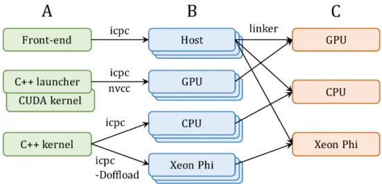
Docking simulations with GeauxDock can be conducted on three platforms, multi-core CPU, GPU and Xeon Phi. Therefore, the source code is modularized for an easy mainte-nance across different architectures (Figure 2.2). All three platforms share a common code for front-end computations, whereas back-end codes have two versions, one for CPU and Xeon Phi, and one for GPU. The C++ kernel employing OpenMP and Intel SIMD prag-mas is shared between CPU and Xeon Phi. Using the “-Doffload” flag enables additional pragmas protected by the “#ifdef offload” macro, which instruct the compiler to generate object files for Xeon Phi instead of CPU. In contrast, the GPU version comprises a C++ launcher and a docking kernel implemented in CUDA. This design allows for maintaining a single front-end code and two versions of the back-end code. Compiling the source codes (Figure 2.2A) generates architecture-specific object files (Figure 2.2B), which are linked to create different versions of the binary (Figure 2.2C).
Figure 2.2: Implementation of GeauxDock. (A) The code repository is divided into three modules, a common front-end module for the CPU host and two back-end modules, one for GPU and one for CPU and Xeon Phi. (B) Compiling the source codes produces a series of architecture-specific object files. (C) Linking object files creates three binary versions for GPU, CPU and Xeon Phi.
2.3.1
PARALLELIZATION LEVELS
GeauxDock features an enormous task-level parallelism, where different library com-pounds docked against the target protein correspond to individual tasks. In addition, the docking kernel exploits coarse- and fine-grained parallelism. Docking calculations for a sin-gle task involve multiple protein and ligand conformations, where each unique combination of protein-ligand conformations is regarded as a replica of the system. Although replicas can be subjected to MMC simulations at different temperatures, only one temperature is cur-rently used. For a given docking task, the corresponding ensembles of independent replicas are suitable for coarse-grained parallel computing. Moreover, a fine-grained parallelization takes place at the level of pairwise interactions between data points within each replica. These interactions are computed as three matrices, proteinColumnV ector ×ligandRowV ector
(P RT), KDEColumnV ector ×ligandRowV ector (KDE), and M CSM atrix ×ligandColumnV ector
(M CS). Here, a fairly large number of computations are subjected to fine-grained paral-lelization; the analysis of input data reveals up to 104 data points for a single replica, which is sufficient to saturate computing resources available on modern CPUs and accelerators.
Table 2 explain mapping between the docking algorithm and computing resources. First, replicas within each task are mapped to coarse-grained resources, GPU streaming multipro-cessors (SMs) as well as CPU and Xeon Phi cores (Figure 2.3A and Table 2, Coarse-grained parallelism). When multiple GPUs are available, replicas within a given task are evenly assigned to the attached GPU cards. Second, interaction-level calculations (Figure 2.3B) are mapped to fine-grained resources, where computing 2D matrices utilizes SIMD lanes on CPU and Xeon Phi, and CUDA threads on GPU (Figure 2.3C and Table 2, Fine-grained parallelism). Code 1 in S1 Codes illustrates loop operations on PRT, KDE, and MCS matri-ces involving a number of summation reductions. For instance, five energy terms calculated using the PRT matrix (Eelesof t, EvdWsof t,EHB, ECP, and ECPP S) are directly reduced from a 2D
array to a scalar value. Another type of reduction is hierarchical, where a 2D array a[i][j] is first reduced to a 1D array b[i] along the j-dimension, and then to a scalar value along the i-dimension. This technique is applied to selected data across all three matrices, e.g., EHP
in the P RT matrix, EKDE in the KDE matrix, and EM CS in the M CS matrix. In order
to implement hierarchical reductions on GPU, I made adjacent GPU threads efficiently exchange data by scheduling the i-dimension as the outer loop, and the j-dimension as the inner loop. Specifically, the outer (inner) loop iterates over ligandRowVector (protein-ColumnVector) for the PRT matrix, ligandRowVector (KDE(protein-ColumnVector) for the KDE matrix, and rows of M CSM atrix (columns of M CSM atrix) for the MCS matrix.
2D CUDA thread blocks are responsible for calculations on GPU (Figure 2.3A, green rounded boxes). The shape and size of CUDA thread blocks are flexible and can be tuned for the optimal performance. Given that the CUDA warp size is fixed at 32, the x-dimension of the CUDA thread block is best defined as a multiple of 32. Also, the maximum number of 1,024 threads per CUDA thread block restricts the y-dimension, for example, the size of the y-dimension cannot be greater than 32 when x-dimension is 32, because 32×32 = 1024. However, the shapes of 2D interaction matrices do not always perfectly match those of CUDA thread blocks. For instance, the x-dimension is always greater than the y-dimension
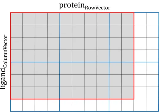
in PRT and KDE matrices, whereas a typical MCS matrix has the y-dimension greater than the x-dimension. Therefore, boundary conditions require a careful design of CUDA thread blocks to leave a certain number of idle threads for the thread management. This procedure is illustrated in Figure 2.4, where processing a small, 70-element data matrix (outlined in red) requires at least six cycles of a 4 × 4 CUDA thread block (each cycle is outlined in blue). With this setup, 70 parallel threads are fully utilized (gray cells), leaving 26 threads idle (white cells). Overall, the number of CUDA threads is fixed at the compiling time, but the optimal shape of the thread block is defined at the runtime, when the input data become available. Here, the objective is to find the best combination of x- and y-dimensions consuming the least amount of computing cycles to traverse the data matrix, where a computing cycle is defined as follows:
cycle=ceiling data sizex cuda threadsx ×ceiling data sizey cuda threadsy (2.1) In practice, only a handful of configurations are valid; I enumerate and evaluate these configurations to find the optimal solution. As an example, using Tesla K20Xm GPU with 1,024 threads per thread block, a typical configuration for PRT, KDE, MCS matrices is 128×8, 128×8, and 32×32, respectively.
Different from the GPU version, the back-end for CPU implemented in C++ with OpenMP pragmas assigns processor threads to carry out computations for individual repli-cas (Figure 2.3A, blue rounded boxes). In order to avoid thread migration and ensure the best cache locality, the environment variable “OMP PROC BIND” is set to “true.” In addition, inner loops in data computations iterating over proteinColumnVector (PRT matrix), KDEColumnVector (KDE matrix), and columns of MCSMatrix (MCS matrix) are marked with vector pragmas to assist Intel compiler in generating an efficient, vectorized code. Note that the same CPU code can be used on Xeon Phi since almost all performance tuning techniques for CPU apply to this accelerator as well. The major difference is that the code for Xeon Phi is required to be offloaded to the accelerator, which is conceptually
similar to GPU programming. The offload is accomplished using compiler pragmas, i.e. “#pragma offload target (mic) in (data in) out (data out). However, the present pragma-based Xeon Phi programing model was designed to offload a block of code to only one device. The current implementation of GeauxDock works only with a single Xeon Phi card. Although replicas could be distributed manually across multiple accelerators, one should keep in mind that at least 240 replicas are required to effectively utilize Xeon Phi. Since docking tasks have no more than 550 replicas, splitting the workload among multiple Xeon Phi cards would inadvertently decrease the overall performance. In addition, any code modification targeting the Xeon Phi platform would complicate the code maintenance. In fact, workload sharing at the task level represents a more practical and scalable approach, which will be implemented in the future release of GeauxDock.
Figure 2.3: Two levels of parallelism in the docking kernel. (A) At the coarse-grained level, individual replicas are assigned to different CUDA thread blocks on GPU streaming multiprocessors (SMs) and different threads on CPU/Xeon Phi cores. (B) At the fine-gained level, data points for each replica are organized as Structure of Arrays containing Cartesian coordinates x, y, z, and parameters p associated with atoms, such as type, charge, and etc. Parameters for neighboring atoms are placed closely in memory to ensure the best execution efficiency. (C) Data points at the fine-gained level are accessed in parallel by CUDA threads on GPU and SIMD lanes on CPU and Xeon Phi.
Figure 2.4: Example of parallel calculations for a data matrix. A small, 96-element matrix ligandColumnVector × proteinRowVector is outlined in red, whereas the 4 × 4 CUDA thread block iterating over the matrix is outlined in blue. Here, at least 6 cycles are required to process the data matrix utilizing a total of 70 parallel threads (gray cells), while the remaining 26 threads are idle (white cells). An optimal shape of CUDA thread blocks can be constructed dynamically to improve the computational performance by reducing the number of cycles required to traverse the data matrix.
2.3.2
DATA STRUCTURE
A docking task contains complex data, including read-only protein and ligand con-formations, MMC simulation parameters, MCS, KDE and PSP force field parameters, as well as the dynamic configuration and output data from individual replicas. GeauxDock employs the Structure of Arrays (SoA) to store the data ensuring the best data locality. For example, the SoA for the ligand conformation shown as Code 2A in S1 Codes con-tains elements x[L], y[L], z[L], t[L], and c[L], representing x, y, z coordinates, the type, and electric charge for all ligand atoms, respectively. L defines the maximum number of ligand atoms and it is set at the compiling time. Figure 2.3B shows that the data associated with neighboring atoms are stored in consecutive memory addresses in order to maximize the efficiency of memory operations required for the fine-grained parallelization. With this
design, CUDA threads on GPU and SIMD lanes on CPU and Xeon Phi access these data in a stride-1 pattern as illustrated in Figure 2.3C. Data structures for protein conforma-tions, MMC simulation parameters, and PSP, KDE and MCS force field parameters are created in a similar fashion. These data constitute the first-level SoA providing read-only information, and are used as building blocks to construct the multiple-replica simulation context.
To systematically assemble replicas from these raw data, I created a data structure called “ReplicaInfo,” whose purpose is to assemble a replica from the raw data using in-direct references to various arrays. The concept of ReplicaInfo is presented in Figure 2.5, where two example replicas, (L1, P1, T1) and (L1, P3, T2), are created using indexes to the same ligand conformation (L1), but different protein conformations (P1 and P3) and simu-lation temperatures (T1 and T2). ReplicaInfo was designed to yield a high computational efficiency of data exchange between replicas during parallel tempering MMC simulations [63], which requires swapping only a few indexes rather than the associated large data ar-rays. Further, the ReplicaInfo structure is used to store the temporary simulation status, including energy values and ligand orientations with respect to the target protein pocket. Simulation logs are saved in the “Simlog” data structure, whose entry can also be found in ReplicaInfo. I note that the ReplicaInfo can be modified during MMC simulations, while the associated data are read-only.
In addition to the first-level SoA, I designed the second-level SoA called the “Complex” (Code 2B in S1 Codes) providing the outermost container for the computation data. The el-ements of Complex are various data structures, including protein and ligand conformations, MMC simulation parameters, MCS, KDE and PSP force field parameters, ReplicaInfo, and the data size. Essentially, a single instance of Complex SoA and Simlog hold all data asso-ciated with a computation task. Because the memory for Complex and Simlog is allocated only once, when either the CPU/Xeon Phi or GPU version of GeauxDock is initiated, it must be large enough to hold data for any docking tasks from the task pool. Docking
cal-culations for the CCDC/Astex dataset require about 5 MB of memory for each Complex, whereas the entire Simlog would allocate about 1.5 GB of memory. In practice, only about 100 MB of Simlog data need to be transferred to the host and saved on disk.
Figure 2.5: Data indexing for multi-replica Monte Carlo simulations. Individual replicas are multi-dimensional objects comprising different combinations of ligand (L) and protein (P) conformations, and temperatures (T), as well as the same set of PSP, KDE, MCS potentials and force field (FF) parameters. All these data are read-only, labeled with tags, and accessible through indexes as depicted by arrows.
2.3.3
DATA REARRANGEMENT
Irregular code patterns caused by dynamic data may significantly affect the perfor-mance. The docking kernel code contains conditional branches and indirect memory ref-erences, for example, calculating a branch path depends on the distance between a ligand atom and a protein point, which is changing in the course of MMC simulations. Although it is difficult to speed up the code containing these dependencies, I improved the code regularity for certain cases. For instance, incrementally sorting KDE data elements by the atomic type t helps improve the regularity of the conditional code “if (lig-¿t[index] == kde-¿t[index])”
memory reference, such as “d = array[ligand-¿t[index]][protein-¿t[index]].” Here, sorting ligand and protein objects by t greatly improves the locality of accessing array elements. Altogether, data rearrangement enhances the performance of GeauxDock by 9.6%, 12.2% and 8.2%, on CPU, Xeon Phi and GPU, respectively.
2.3.4
STRENGTH REDUCTION
In order to further speed up calculations within the docking scoring function, the strength reduction technique is applied to reduce its computation complexity. Original mathematical formulas for various energy terms in the MMC kernel are divided into pre-processing and computation groups. The pre-pre-processing combined with data transforma-tion is conducted within the front-end of GeauxDock. An example is shown as Code 3 in S1 Codes, where the indirect memory reference “prtconf.r[index]” is removed from the original kernel (Code 3A) and included in the pre-processing stage (Code 3B), leading not only to a better memory locality, but also to fewer instructions in the optimized kernel. Another technique used to accelerate computations within the docking kernel is the reduction of the arithmetic intensity. For instance, Code 4A in S1 Codes shows a part of the original kernel computing the soft van der Waals potential, which includes 6 loads, 9 multiplications, 3 division and 5 power functions. To speed up the MMC kernel, some calculations are either moved to the pre-processing step or executed between certain blocks of the code and then reused when calculating the potential. As the result, the optimized code shown as Code 4B in S1 Codes has only 2 loads, 6 multiplications, 3 divisions and no power functions.
2.3.5
GPU-SPECIFIC TUNING
The power of accelerators can be fully utilized only when time is primarily spent on computations rather than data communication. GeauxDock is implemented based on this principle by moving compute-intensive MMC simulations to Xeon Phi and GPU. Code 5 in S1 Codes shows the MMC conformational sampling in ligand docking. First, a new
configuration of a ligand is generated by randomly perturbing the present configuration. Next, the energy of the new configuration is calculated and compared to the energy of the old configuration using the Metropolis algorithm [64]; the new configuration is accepted with a certain probability to be used in the next iteration, otherwise it is rejected. Even though some components of the docking kernel, such as evaluating the Metropolis criterion, are less suitable for the parallelization on GPU and Xeon Phi, this approach yields a better overall performance than offloading parts of the docking kernel. For instance, offloading only energy calculations could potentially generate an excessive communication between the host and the accelerator. In that case, advanced optimization techniques such as the asynchronous kernel execution and data copying between multiple tasks would have to be applied for a better performance. However, because extra communication is avoided in the MMC kernel, the code requires no further optimization of data transfer.
For GPU, the memory is carefully managed within the GeauxDock code with heavily reused variables, such as interaction distances, placed in registers. Moreover, the shared memory is used for those frequently reused data, such as ligand coordinates and energy parameters, which may have an irregular access pattern. Large arrays with the stride-1 parallel access pattern are defined as SoA, sorted for improved regularity, and saved in the global memory. Importantly, level 1 data cache on Tesla K20Xm GPU does not buffer the global memory traffic by default. The docking kernel has a good reuse pattern for PRT and KDE matrices, therefore, inserting ldg intrinsic enables the level 1 data cache mechanisms to enhance memory operations. This technique improves the GPU performance by 4% for PRT and KDE matrices. In contrast, the cache optimization cannot be applied to computations for the MCS matrix, which have no global data reuse at all.
Since the docking kernel invokes reduction operations, partial results in each CUDA thread need to be added to a scalar value. Here, a simple implementation stores temporary data in the shared memory, where the amount of the required memory scales linearly with the number of CUDA threads. In the early version of GeauxDock, the capacity of the
shared memory limited the maximum number of CUDA threads per thread block to 768. Since using more CUDA threads per block generally delivers a better performance on Tesla K20Xm GPU, the current docking kernel uses shfl and shfl xor intrinsic instructions for reduction operations. This technique enables a direct data exchange between CUDA threads without consuming the shared memory. Not only is the new reduction code 3
× faster, but it also allows to use 1,024 CUDA threads per block improving the overall performance by 40%. Finally, many elementary functions, exp, log, sin, cos, etc., are frequently used in the docking kernel. The CUDA math library offers accelerated versions of these math functions [20], which are enabled by the “-use fast math” compiler flag. This tuning yields a 30% performance boost, however, the fast math intrinsic for GPU is not guaranteed to be fully compatible with the IEEE floating point standard. Nonetheless, a careful comparison of the results against the CPU code shows that the error rate is smaller than 0.0001
2.4
RESULTS
The performance of MMC kernels in GeauxDock is evaluated on several computing platforms using diverse input data. I conducted benchmarking calculations using four Linux computers listed in Table 3, including a mainstream PC desktop, a PC desktop with the latest consumer grade GPU, a heterogeneous HPC cluster node with both GPU and Xeon Phi accelerators, and an HPC cluster node with two GPU cards. I set the optimiza-tion level to “-O3” with the following addioptimiza-tional flags for the Intel compiler: “-fno-fnalias -ansi-alias -fargument-noalias” (to safely remove pointer aliases), “-ipo” (to enable inter-procedural optimization), “-vec-threshold0” (to enable vectorization whenever possible), and “-fma” (to enable the fused-multiplication-add code generation). Architectural events listed in Table 4 were recorded by hardware counters using the Performance Application Programming Interface (PAPI) library version 5.4.0 [65]. In addition, I implemented timers directly in the code in order to measure the execution time of an arbitrary segment of the
code. I noticed that time measurements have minor fluctuations of nearly 5%, therefore, all timings are reported as the average over 8 independent runs.
Benchmarking calculations are carried out for a single target protein, the pp60(c-src) SH2 domain complexed with ace-malonyl Tyr-Glu-(N,N-dipentyl amine) (PDB-ID: 1a07) [66] and a set of 204 drug compounds selected from the CCDC/Astex dataset [67]. 1a07 represents a typical docking target with 344 protein effective points and an ensemble of 11 protein conformations. Depending on the number of rotatable bonds, up to 50 con-formations are generated for ligands, thus the ensemble-based docking employs up to 550 replicas (11×50) of individual systems. In addition to this default protocol, I test the code scalability using a varying number of replicas at multiple temperatures. Other parameters affecting the computational complexity are the number of non-hydrogen ligand atoms and the number of points to compute the evolution-based components of the GeauxDock force field, KDE and MCS. Although both KDE and MCS scoring terms are used to calculate various restraints derived from homology rather than physical interactions, these points are iterable from the computing point of view. Therefore, KDE and MCS interacting points are equivalent to ligand atoms and protein effective points in the physics-based components of the GeauxDock force field.
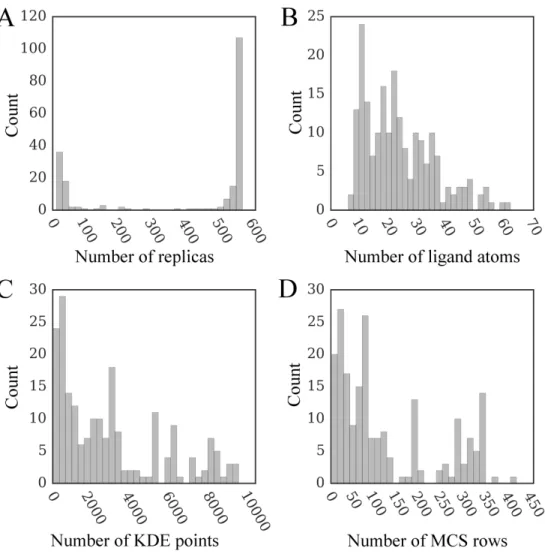
The distributions of the number of replicas, ligand atoms, as well as KDE and MCS points are shown in Figure 2.6. GeauxDock employs multiple replicas to account for the flexibility of protein-ligand complexes, where each replica contains a unique combination of protein and ligand conformations. The highest peak in Figure 2.6A at around 550 replicas corresponds to highly flexible compounds with multiple rotatable bonds, whereas the smaller peak at around 11 replicas represents those rigid complexes having only a single conformer. Given that the hydrogen atoms are omitted when counting atoms, the range between 6 and 62 heavy atoms presented in Figure 2.6B agrees well with the qualifying range for drug molecules according to the extended version of Lipinski’s rule-of-five [68]. Because KDE points and rows in MCSMatrix are calculated using template-bound ligands detected
by the eFindSite algorithm [61], their distributions (Figures 2.6C and 2.6D, respectively) depend on the number and size of ligands extracted from holo-templates.
Another important simulation parameter is the number of MMC cycles. I found that 1,000 MMC cycles is sufficient for production runs to converge. Since these calculations require 4.8 to 61 minutes on various platforms, the average wall time for the docking kernel is 1.4 seconds on the fastest machine (platform D2, Table 3) and 18 seconds on the slowest computer (platform D1, Table 3). Because the number of replicas (up to 550) is multiplied by the number of temperatures (up to 240) in our benchmarks, and several versions of the docking code needed to be tested, the time required to complete simulations could be hundreds times longer than that for production runs. Therefore, shorter simulations with 100 MMC cycles are used for benchmarking purposes.
2.4.1
PERFORMANCE WITH AN AMPLE COARSE-GRAINED
PARALLELISM
The execution time for docking kernels includes not only computations but also time required for the data transfer to and from accelerator devices. Moreover, the kernel perfor-mance can be affected by the ensemble size (the number of replicas), because those docking systems containing rigid ligands provide insufficient coarse-grained parallelism to fully uti-lize computing resources. On that account, I first need to determine the ideal performance as well as a performance penalty caused by the meager coarse-grained parallelism. To address this problem, I conducted a series of simulations providing a sufficient number of replicas to deliver an ample coarse-grained parallelism. Specifically, I used 400 replicas for a dual CPU with 20 cores and 20 threads, 2,400 replicas for Xeon Phi with 60 cores and 240 threads, and 280 replicas for GPU with 14 streaming multiprocessors and 14 CUDA thread blocks.
The performance of docking kernels on CPU is assessed using the C1 computing sys-tem (Table 3). I first evaluate the serial performance by enabling only 1 thread on a
Figure 2.6: Distribution of various parameters affecting docking time for the dataset of 204 CCDC/Astex compounds. The number of (A) replicas, (B) ligand non-hydrogen atoms, (C) KDE points, and (D) rows in the MCS matrix. KDE (Kernel Density Estimation) and MCS (Maximum Common Substructure) points are used to calculate evolution-based components of the docking force field.
single processor core. Using the total number of CPU cycles according to the PAPI event PAPI TOT CYCLES (Table 4) and the computing time measured by either the PAPI timer or our timer, the average dynamic CPU clock rate is 3.58±0.02 GHz. Figure 2.7 shows several characteristics assessing the overall computational performance of the docking code. In most cases, the number of level 1 data cache misses per 103 instructions is less than 7 (Figure 2.7A), which is lower compared to a broad distribution of 5-30 misses reported for thoroughly tuned SPEC CPU2006 benchmark kernels [69] tested on the same CPU microarchitecture. Similarly, the number of branch mis-predictions per 103 instructions