A finite-difference method for the prediction of velocity
field in extrusion process
Gino Ferretti, Roberto Montanari
*Dipartimento di Ingegneria Industriale, Universita` degli Studi di Parma, Viale delle Scienze, 43100 Parma, Italy
Received 26 September 2006; received in revised form 30 December 2006; accepted 3 January 2007 Available online 18 January 2007
Abstract
Extrusion defects and flow instabilities are an important limitation in most product processing operations. Investigation of the fluid kinematics to deduce the dynamical response of the fluid can be very useful to characterize these instabilities and understand the mech-anisms involved in their triggering and enhancement. To do so, the flow of a Newtonian fluid through a screw press has been studied in order to predict the downstream velocity field in extrusion process. Flow in the screw press is modeled by adapting the classical theory of single screw extrusion. Some publications have addressed this subject matter, especially in the nineties. However, most of these publica-tions develop models that are not so easy to apply. To complement those earlier works, an approximate model base on finite-difference method is developed. The models in this paper may be considered as of pedagogical value because of the ease of their application; none-theless, results are obtained basing on the real extruding conditions, such as a general screw geometry. In order to achieve this pedagog-ical purpose, three important properties pertaining to model building are considered in this article. These properties are applicability, simplicity, and level of technique applied. Moreover, the models introduced in this paper are straightforward application by both prac-titioners and students. The ease of the applicability is confirmed by the suitability to adopt a widely employed software, such as Micro-soft Excel, to implement the model developed.
Ó2007 Elsevier Ltd. All rights reserved.
Keywords: Extrusion; Finite-difference; Downstream velocity field
1. Introduction
At the beginning, single screw extruders have been widely used in the polymer industry, but in the last decades they have been extensively applied in the ceramic, food and pharmaceutical industries, due to the fact that they are cheap, robust and continuous.
Extruders geometry is an important parameter of the extrusion process, since it affects shear rate and residence time values, involving direct outcomes on the quality of the final product. Defects and flow instabilities are impor-tant limitations in processing operations of most extruded products. Investigating fluid kinematics to deduce the
dynamical response of the fluid can be very useful to char-acterize those instabilities and understand the mechanisms involved in their triggering and enhancement. In addition, better control on the downstream velocity field in extrusion process can be a significant source of quality differentiation between food products. In other words, a more regular profile and lower values of the mean shear rate along the extruder determine a reduced gelatinization of the com-pound. Conversely, extruders characterized by high values of shear rate can involve several issues in controlling the final quality of the products, due to the complex behavior of the shear rate profile along the screw axis.
On the ground of these premises, models for predicting the extrusion process variables have been receiving ever increasing attention by the researchers. Until the 1970s, food extrusion was regarded as an art rather than a science; thus, only trained and experienced personnel could handle
0260-8774/$ - see front matterÓ2007 Elsevier Ltd. All rights reserved. doi:10.1016/j.jfoodeng.2007.01.002
*
Corresponding author. Tel.: +39 0521 905051; fax: +39 0521 905705.
E-mail address:[email protected](R. Montanari).
such equipment. However, over the past 30 years and espe-cially in the nineties, several models have been developed to predict process throughput, energy requirements, mixing patterns and residence time distribution of extruders. One of the earliest models for single screw extrusion was pre-sented by Darnell and Mol (1956). The model developed by the authors described plug flow of a solid feed material along a screw of constant pitch and depth. The original approach proposed by Darnell and Mol (1956) has been subsequently developed by Burbidge and Bridgwater
(1995), Englander, Burbidge, and Blackburn (2000), by
adding the rheological parameters characterizing pasty feed materials. Following a similar approach, further authors focused on extrusion process for food materials. Among recent works,Vergnes, Le Roux, Chaurand, and Abe´cassis
(1995), developed and experimentally validated a
thermo-mechanical model for pasta extrusion. More specifically, the flow along the screw channel was computed using finite element simulation and described by means of an approxi-mate model, which has been derived starting from well-known analyses of plastic extrusion. Karwe, Chiruvella,
and Jaluria (1996), studied the behavior of starch-based
materials under high temperature environment, by a numer-ical simulation of flow inside a single screw extruder.Elsey,
Riepenhausen, Mckay, Barton, and Willis (1997),
devel-oped a flexible dynamic model of the extrusion process in order to predict and control realistic quality variables, such as product gelatinization fraction. Along the same line, the earlier work ofBlackburn, Bottena, and Burbidgea (2003), presented a general one-dimensional model for the predic-tion of the pressure field in single screw extrusion including corrections for non-constant channel depth in the screw.
As stated above, several models have been developed and presented on extrusion processes. Nevertheless, the analysis of the scientific literature has pointed out that the issue of accurate predicting the velocity distributions has been somehow neglected. In particular, issues such as how to predict the downstream velocity field in extrusion processes have not received the required attention in tech-nical literature and only few authors faced this challenge.
Both mathematical and experimental approaches have been employed to achieve the required accuracy in order to describe and solve more realistic generalized problems.
Choo, Neelakantan, and Pittman (1980), developed a
com-puter model for flow in a single-screw extruder, pumping a Newtonian liquid under isothermal and developed flow conditions. Flow rate, screw speed, and pressure gradient characteristics were measured, and a tracer particle tech-nique was employed to determine channel velocity profiles. The data were required for the testing the model which takes into consideration channel curvature. Using the resulting experimental data, Li and Hsieh (1996), devel-oped and tested an analytical solution of an isothermal, Newtonian fluid in a single screw extruder with finite chan-nel. Following this analytical approach, Yu and
Gunasek-aran (2003), proposed and tested a numerical approach to
analyze flow field and heat transfer developed inside a sin-gle-screw channel. Finite-difference and finite element methods were used to obtain numerical solutions for flow and energy equations also in the case of non-Newtonian fluids. Along the same line, but more focused on experi-mental approaches, Bakalis, Cox, Russell, Parker, and Fryer (2006), analyzed velocity distributions in single-screw extruder a specially designed and manufactured, by using positron emitting particle tracking. In particular, velocity profiles in the extruder, that could be predicted by compu-tational fluid dynamics were generated, measured and com-pared to the experimental data by setting process parameters, flow rate and rotational speed in the range used in commercial processes.
On the ground of literature analysis, it can be right stated that most of the papers examined present approaches that are able to accurately predict the down-stream velocity field in extrusion process. However, it is also self-evident that the way approaches were developed has can significantly affect both their practical applicabil-ity and their degree of current adoption. Generally speaking, the higher the accuracy of the approach pro-posed, the higher the resulting complexity of the model; consequently, higher difficulties may be involved in
prac-Nomenclature
Db internal barrel diameter
Rs screw root radius x rotation sped of screw
W width of channel at the internal radius of barrel
H channel depth
h helix angle of screw
hb helix angle of screw at internal barrel radius that
isRs+H
l viscosity of the Newtonian fluid
Vs screw root velocity
x down channel coordinate
y channel depth coordinate
z channel width coordinate
Vx,Vy,Vz velocity component of x,yandzdirections
oP
ox pressure gradient in down channel direction oP
oy pressure gradient in channel depth direction oP
oz pressure gradient in channel width direction
ni,j generic node (i,j) in anW*nHgrid mesh
nW,nH number of nodes alongzandydirection
hz,hy distance between two adjacent nodes along z
andy direction
tical implementation of the model itself. As a result, a necessary trade-offs between model complexity and prac-tical applicability rise. Moreover, in some cases a detailed explanation on how to apply well-know tech-niques, such as finite-difference methods, exploiting widely employed software (e.g. MS Excel) should be con-sidered as essential for the applicability of the models developed. The analysis of scientific literature related to the extrusion process, and in particular to the down-stream velocity field, has pointed out that the issue of how readers could apply the proposed models has been somehow neglected.
Based on these premises, the aim of this paper is two-fold. First, we propose a finite-difference approach for predicting the downstream velocity field in extrusion pro-cess. Fluid flow in the screw press is modeled by adopting the classical theory of single screw extrusion for Newto-nian fluids in a general screw geometry. In addition, we present a detailed numerical case study, in order to pro-vide the required knowledge for a quickly propagation of the model without expensive and obscure software. Usually, these tools act as black boxes where only few people know how they work and consequently only few people have a full control on them. To overcome this problem the numerical case study is developed step by step by user-friendly and widely employed software as MS Excel.
The model proposed in this paper may be considered as of pedagogical value because of its applicability, simplicity, and good performance in predicting the velocity field val-ues. Moreover, the model introduced in this paper is of straightforward application by both practitioners and stu-dents. The ease of the applicability is confirmed by the suit-ability to adopt a widely employed software, such as Microsoft Excel, to implement the model developed. The good performance of the model is confirmed by the com-parison between numerical results and experimental data from published literature.
This study is part of a wider project aiming to control microbiological parameters of extruded products. The whole project is founded by Regione Emilia-Romagna inside the PRRITT (Programma Regionale per la Ricerca Industriale, l’Innovazione e il Trasferimento Tecnologico).
2. Safety emphasis
This study is part of a wider project whose aim is to define process operative leverages in order to control microbiological polluters in food extruded products. In particular, a mathematical model, and subsequently a simulation software, will be developed in order to predict physical properties affecting the proliferation of microbio-logical polluters in products during the whole process. Thanks to the software developed, proper conditions could be designed to optimize the safety of the extrusion process.
3. Mathematical formulation
The material fed to the screw extruder passes through a relatively long, shallow helical channel formed by the flight of the screw.
The channel bounded by the inner surface of the barrel, the root of the screw and the flight. In order to simplify the problem many approaches hypothesize stationary screws and rotating barrels (in opposite direction). This does not alter the analysis when the internal barrel diameter is much larger then the channel depth. Nevertheless,Li and Hsieh
(1996), underlined the source of error and they proposed
a new analytical solution for flow in extruder with a rotat-ing screw and stationary barrel. In accordance withLi and
Hsieh (1996), and in order to provide better and more
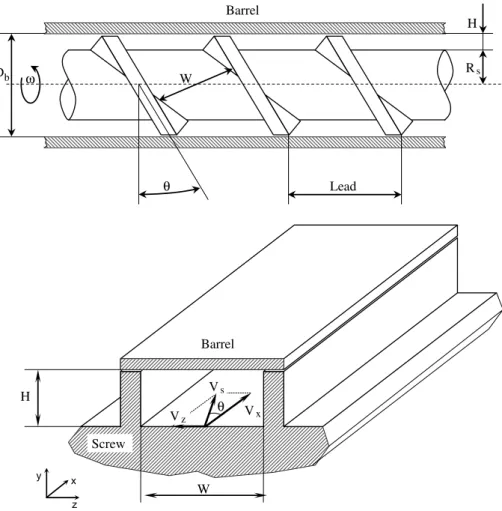
real-istic results, the model developed exploits a rotating screw and stationary barrel approach. The channel and the screw geometry studied is qualitatively shown in Fig. 1; in the scheme,x,yandzrepresent channel down stream, channel height and channel width directions, respectively.
Since in many practical extruders the height of the screw channel is much less than the barrel diameter, the screw curvature is assumed to be very small. As a consequence, the barrel surface and the screw channels can be mathemat-ically modelled as unwrapped. In other words, from a geo-metrical point of view, the higher the ratio of the barrel diameter to the height of screw channel, the lower screw curvature should be and the screw channel tends to become flat plate. This does not alter the analysis, since centrifugal force are negligible. In order to further simplify the prob-lem, the following assumptions are commonly used without losses in accuracy:
fluids flow is assumed as laminar, since the very high vis-cosity of the common extruded fluid (>103Pa s) leads to Reynolds numbers much less than unity;
the inertia terms in the Navier–Stokes equation can be neglected in comparison with viscous and pressure terms;
gravitational force is negligible;
the fluid is incompressible and Newtonian;
the flow is fully developed;
no slips at the walls occur.
Under these hypotheses, equations describing fluid motion for this problem in rectangular coordinates can be expressed as follows: oP ox ¼l o2Vx oy2 þ o2Vx oz2 xcomponent oP oy ¼l o2Vy oy2 þ o2Vy oz2 y component oP oz ¼l o2Vz oy2 þ o2Vz oz2 zcomponent ð1Þ
Assuming that Vy0, which is a reasonable
H/W, and using the continuity equation; then,oVy/oz0, oVz/ox0, andoVy/oy0. Thus Eq.(1)becomes:
oP ox¼l o2Vx oy2 þ o2Vx oz2 xcomponent oP oy 0 y component oP oz l o2Vz oy2 zcomponent ð2Þ
The above simplified equations of motion can be found in
Li and Hsieh (1996). Since the proposed model utilizes a
rotating screw and stationary barrel approach, boundary conditions should take into account the screw velocity. In particular, the screw flight velocities are not constant but variable as a function of the radius; from the mathematical point of view, in the case of thex-component the function is expressed in the following boundary conditions:
Barrel Vxðz;HÞ ¼0
Screw root Vxð0;yÞ ¼xRscosðhÞ Vxð0;yÞ ¼xðRsþyÞcosðhÞ
Screw flights VxðW;yÞ ¼xðRsþyÞcosðhÞ
ð3Þ
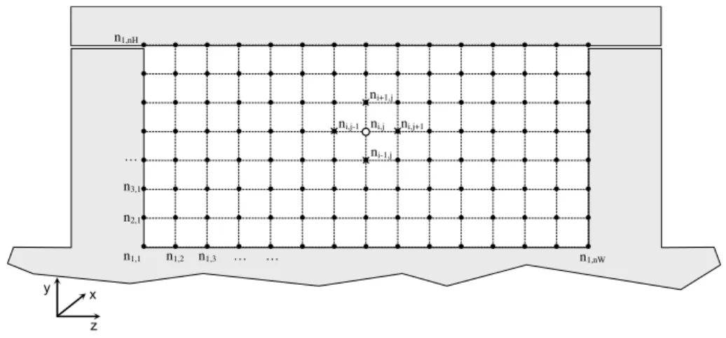
As can be seen from the above equations, the x -compo-nent of Eq. (2) is a non-homogeneous, second order par-tial differenpar-tial equation with non-homogeneous boundary conditions. Li and Hsieh (1996), proposed an analytical solution of this problem for finite rectangular channel. In order to extend the solution to a general duct geome-try, a finite-difference method is applied to solve the dif-ferential x-component equation. To this extent, the domain is discretized by imposing a grid defined for a set of nodes ni, j (see Fig. 2).
On the ground of these premises, the x-component of the above equation can be written in discrete form as fol-lows (the mesh is annW*nHgrid alongzandydirection, respectively): oP oxl Vxðiþ1;jÞ 2Vxði;jÞ þVxði1;jÞ h2y þVxði;jþ1Þ 2Vxði;jÞ þVxði;j1Þ h2z ! ð4Þ
Hence, for an estimated pressure gradient in the down channel direction, the component of velocity Vx(i,j) for
the (i,j) node inxdirection becomes:
W H Vx θ Vz x z y Screw Barrel Vs θ W Db Lead H Barrel ω Rs
Vxði;jÞ h2yh2z 2ðh2yþh2zÞ Vxðiþ1;jÞ þVxði1;jÞ h2y " þVxði;jþ1Þ þVxði;j1Þ h2z 1 l oP ox # ð5Þ
It is noteworthy that the velocity value in the generic node (i,j) is a function of the velocity values close to the node it-self, and, in particular, these are the velocity value at the up node Vx(i+ 1,j), the velocity value at the down
node Vx(i1,j), the velocity value on the right side node
Vx(i,j+ 1), and the velocity value on the left side node
Vx(i,j1) as shown inFigs. 2 and 4. These velocity values
have been derived in the previous iteration and are as-sumed as constants for the current iteration. Since bound-ary conditions are constant along the procedure, Eq. (5)
can be adopted iteratively for each node in the mesh (ex-cept the boundary nodes) until a required level of accuracy is achieved.
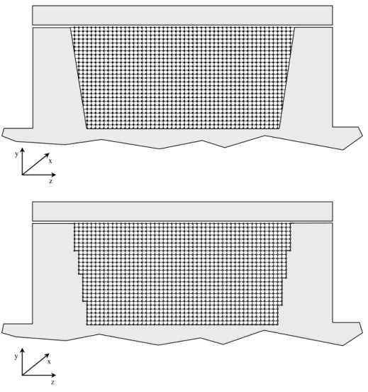
Based on the same rationale, slanted walls of the chan-nel can be taken into account by a suitable mesh as shown inFig. 3.
As an oblique line can be shown in a PC monitor by pix-els, slanted walls of the channel can be modeled by rectan-gular grid and, as can be seen in Fig. 3, the higher the number of nodes, the higher the quality of the model should be.
As shown inLi and Hsieh (1996), for the cross channel flow, z component of Eq. (2) can be integrated twice to yield: Vz¼ Rs x sinhbðHyÞ H 3 y H1 h i þ6Qleakage ½Hyy 2 H3 4. Software implementation
Nowadays, commercial solutions are available to solve complex fluid dynamic problem, although these solutions are often expensive, unknown, and not user friendly if compared to spreadsheet programs which are
available in widespread, cheap and user friendly software packages as MS Office, Star Office or Open Office. Besides, as stated above, the commercial solutions for solving complex fluid dynamic problem, in several cases, act as black boxes and only few people know how they exactly work; consequently, few people have a full control on them. This means that few people can utilize and fully understand the outcomes from the software. Conversely, when adopting user friendly and widely employed softwares, a general model can become a powerful tool for a large number of users. To this extent, and due to its wide employment, a MS Excel implementation of the presented approach has been developed.
Due to its framework, MS Excel is particularly suitable to solve the finite different approach. As well known, it is structured by cells can contain labels, numerical values and mathematical relationships between cells. Due to its similarity to the finite different approach, this structure is particularly appropriate to describe the mesh and the mathematical relationships between each node. In other words, each cell in MS Excel is approached as a node, where both numerical value and analytical formula repre-sent the down stream velocity and the mathematical rela-tionship to solve the problem, respectively. Moreover, thank to the large number of available cells, MS Excel is particularly suitable to be adopted to implement the itera-tive approach required to achieve a defined level of accuracy.
Once the number of nodes is defined, the cells in MS Excel to be implemented, can be identified. Clearly, the higher the number of nodes of the mesh, and consequently the number of cells involved, the higher the resulting accu-racy of the model. Following the boundary conditions of Eqs.(3), the boundary cells have to be implemented with the respective formulation, whereas the others cells have to be initially set to 0.Fig. 4shows the mesh (the boundary cells are in grey) at the iterative step 0, the related data and the screw flights velocity formulation in a boundary cell on the left side.
ni,j ni+1,j ni-1,j ni,j+1 ni,j-1 x z y n1,1 n1,2 n1,nW … n2,1 n1,nH … n1,3 … n3,1
In order to develop the iterative procedure, a set of tables have to be computed. In other words, Eq. (5)
has to be adopted for the inside cells where the velocity
values close to the specific cell (i.e. Vx(i,j+ 1),
Vx(i,j1), Vx(i+ 1,j) and Vx(i1,j)) are obtained in
the previous table and are treated as constants values
z x y z x y
Fig. 3. Discretized domain with slanted walls.
for the current table (see Fig. 5). To this extent, to implementing the iterative procedure the user can quickly copy the second table as shown in Fig. 5. The higher the number of iterations, and consequently the number of tables computed, the higher the accuracy of the model.
It is noteworthy that the above implementation devel-oped for a rectangular channel can be easily extended to applications for general channel geometry: different geom-etries can be built by simply adding and/or removing opportune cells in MS Excel.
5. Results
To assess validity and accuracy of the proposed approach, results provided by the finite-difference meth-odology are compared with those presented in published papers. Since experimental and/or analytical data are currently available only for rectangular channel, the application is developed with a rectangular dept. The
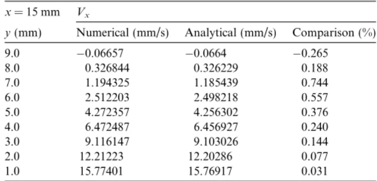
predicted down channel velocity is compared with the analytical solution proposed by Li and Hsieh (1996), whose approach was validated by experimental results measured by Choo et al. (1980). Table 1 shows the per-tinent data, whileTable 2shows the down channel veloc-ity computed and the comparison results in the middle of the channel.
As can be observed from Table 2, the difference is less than 1% even when only a 1030 mesh is used. These results are obtained after only 79 iterations. Clearly, the higher the number of iterations and the higher the number of nodes in the mesh, the higher the accuracy should be. It is noteworthy that the user can suitably set these two parameters in order to achieve a desired level of accuracy. In this case study, the maximum differ-ence less than 1% from the analytical solution proposed
by Li and Hsieh (1996), is the criteria utilized for
decid-ing when the solution had converged.
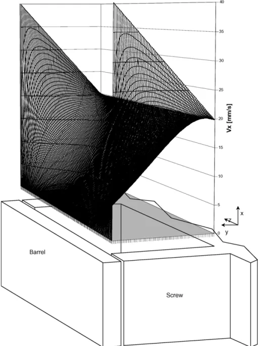
In Fig. 6, the three dimensional down channel
velocity representation is shown by MS Excel surface graph.
Fig. 5. Iterative MS Excel application.
Table 1 Pertinent data H 10 mm W 30 mm hy 1 mm hz 1 mm nH 11 nW 31 Rs 9 mm l 10,000 Pa s /b 0.7889 Rad x 3.125 1/s Vx 19.818 mm/s oP/ox 5000 Pa/mm Table 2
Down channel velocity
x= 15 mm Vx
y(mm) Numerical (mm/s) Analytical (mm/s) Comparison (%)
9.0 0.06657 0.0664 0.265 8.0 0.326844 0.326229 0.188 7.0 1.194325 1.185439 0.744 6.0 2.512203 2.498218 0.557 5.0 4.272357 4.256302 0.376 4.0 6.472487 6.456927 0.240 3.0 9.116147 9.103026 0.144 2.0 12.21223 12.20286 0.077 1.0 15.77401 15.76917 0.031
6. Conclusions
The paper proposes a finite-difference approach for solving the down channel velocity in a single screw extru-der of a Newtonian fluid. The approach completes those existing in today’s literature by adding an efficient as well as easy to apply procedure to obtain the velocity field. Moreover, the model may be considered as of pedagogical value because of its applicability, simplicity, and level of technique applied. Moreover, the model introduced in this paper is of straightforward application by both practitio-ners and students. Since of a user friendly, widely employed, and cheap software as MS Excel is utilized for implementing the model, the proposed approach becomes an interesting and practical tool aiming at a
quickly propagation. In other words, this study has pre-sented a tool that can be adopted by every people for con-structing the screw characteristics and the analyzing the extruder performance.
The predicted down channel velocity data are compared with the analytical data ofLi and Hsieh (1996), that were validated with the experimental data of Choo et al.
(1980). Testing the proposed approach for a small mash
(1030 nodes), has yielded less than 1% difference, pro-viding good findings of the methodology developed.
The fully developed velocity profile reveals important information about the effect of the screw flight. Besides, it represents the starting point for the fluid dynamic and thermodynamic approach for the purposes of screw design and extrusion simulation.
Acknowledgement
The authors appreciate the efforts and the constructive comments of the anonymous reviewers that have helped in sharpening the manuscript.
References
Bakalis, S., Cox, P. W., Russell, A. B., Parker, D. J., & Fryer, P. J. (2006). Development and use of positron emitting particle tracking (PEPT) for velocity measurements in viscous fluids in pilot scale equipment.
Chemical Engineering Science, 61, 1864–1877.
Blackburn, S., Bottena, J., & Burbidgea, A. S. (2003). A model to predict the pressure development in single screw extrusion. Journal of Materials Processing Technology, 135(2–3), 284–290.
Burbidge, A. S., & Bridgwater, J. (1995). The single screw extrusion of pastes.Chemical Engineering Science, 50, 2531–2543.
Choo, K. P., Neelakantan, N. R., & Pittman, J. F. T. (1980). Experimental deep-channel velocity profiles and operating
character-istics for a single-screw extruder. Polymer Engineering and Science, 20, 349–356.
Darnell, W. H., & Mol, E. A. J. (1956). Solids conveying in screw extruders.Social Physics Engineering Journal, 20–29.
Elsey, J., Riepenhausen, J., Mckay, B., Barton, B., & Willis, M. (1997). Modeling and control of a food extrusion process. Computers and Chemical Engineering, 21, 361–366.
Englander, A., Burbidge, A. S., & Blackburn, S. (2000). A preliminary evaluation of single screw paste extrusion. Chemical Engineering Research and Design, 78, 790–794.
Karwe, M. V., Chiruvella, R. V., & Jaluria, Y. (1996). Numerical simulation of the extrusion porcess for food materials in a single-screw extruder.Journal of Food Engineering, 30, 449–467.
Li, Y., & Hsieh, F. (1996). Modelling of flow in a single screw extruder.
Journal of Food Engineering, 27, 353–375.
Vergnes, B., Le Roux, D., Chaurand, M., & Abe´cassis, J. (1995). A thermo-mechanical approach to pasta extrusion. Journal of Food Engineering, 26, 351–368.
Yu, C., & Gunasekaran, S. (2003). Modeling of melt conveying in a deep-channel single-screw cheese stretcher. Journal of Food Engineering, 61(2), 241–251.