INTRODUCTION
This section provides a basic procedure for on-line configura-tion, and shows both the state of LEDs 7 and 8 as well as the contents of the second module status byte (specifically bits 7, 6, 3 and 1). On-line configuration, used with redundant Multi-Function Controllers (MFC), enables you to make config-uration changes without affecting the primary MFC or inter-rupting the control process.
In redundant MFC configurations, the primary MFC executes the process control logic while the backup MFC tracks the con-figuration of the primary. On-line concon-figuration allows the user to remove the backup MFC from the tracking mode and make configuration changes, without interrupting the process con-trol operation of the primary MFC. Normal off-line changes are supported by on-line configuration. When the backup MFC is reconfigured, it can assume control with the new configuration while the original primary MFC takes the backup role.
During start-up of the new configuration in the backup MFC, the present values of all process outputs in the primary MFC are used. This feature permits bumpless transfer of control to the new configuration.
SETUP
On-line configuration of redundant MFCs requires two consec-utive module bus addresses to be reserved. In normal opera-tion each member of the redundant pair has the same module bus address. (If the module bus address of the redundant pair is at 4 during normal operation, then automatically the mod-ule bus address of the backup MFC is at 5 during on-line configuration).
Set Switch 2 on Dipswitch SW4 (see Figure 3-1 in Installation section) of the backup and the primary MFC to the open posi-tion. Doing so enables the use of on-line configuraposi-tion.
OPERATION
The following procedure shows how to perform on-line configu-ration. These standard INFI 90 configuration tools can be used to do on-line configuration: Configuration and Tuning Module (CTM), Configuration Tuning Terminal (CTT), Operator Inter-face Station (OIS), Management Command System (MCS), and
Engineering Workstation (EWS) with PC-90 Ladder Software or CAD/TEXT.
NOTE: Be careful when using either PC-90 Ladder Software or
CAD/TEXT to avoid deleting blocks and/or adding blocks in the mid-dle of existing ones. Refer to the note preceding Step 3 of the backup cycle for a further explanation.
See Figure 5-1 in Operation section for the front panel LED positions. The status of LEDs 7 and 8 is indicated for each step of the backup and primary cycles. Refer to Table 6-1 for LED error codes.
For example, do not reset an MFC before its CPU LED 7 lights. When lit, this LED tells the user that a successful copy of the configuration has been made. Resetting the MFC before this copy is complete could result in unpredictable MFC operation and/or loss of output data.
NOTES:
1. In some applications, you may not be able to see the LEDs of remote MFCs. In these applications, use the data from the second module status byte.
2. The value of bit 7 depends on the communication module resid-ing in the same module bus as the MFC.
The specific interface device determines how module status is acquired. For example: using an operator interface station WARNING
Strict adherence must be made with regard to the rules set forth in this document. Follow all steps in the sequence given and at no time change configurations or remove the module before the LEDs instruct you to do so. Failure to heed this warning and follow proper procedures could result in unpre-dictable MFC operation and/or loss of output data.
ATTENTION
Les procedures decrites dans ce document doivent etre suiv-ies a la lettre. Respecter l'ordre des etapes, et ne jamais apporter de changements a la configuration ou retirer le mod-ule du chassis de montage avant que les temoins DEL ne l'autorisent. Tout ecart a la procedure decrite peut mener a un fonctionnement anormal du MFC et/ou entrainer la perte des signaux de sortie.
problem report option is available in the modify mode menu of the CAD/TEXT software.
NOTE: The LED displays show the CPU operating state. Errors may
occur during on-line configuration that are not exactly described by the LED displays listed in this section. The LED displays indicating these errors are written in the MFC Product Instruction manual.
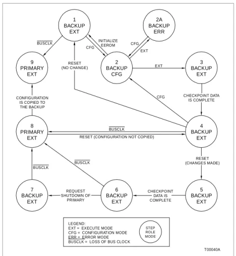
Figures A-2 and A-3 illustrate the backup and primary cycles. For clarity, the term backup MFC will always refer to the origi-nal backup MFC and the term primary MFC will always refer to the original primary MFC. When the roles are reversed for either unit, their status will be carefully noted.
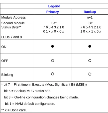
Legend Primary Backup Module Address n n+1 Second Module Status Byte** Bit* 7 6 5 4 3 2 1 0 0 1 x x 0 x 0 x Bit 7 6 5 4 3 2 1 0 1 0 x x 1 x 0 x LEDs 7 and 8 ON
z
z
OFF { { Blinking5
5
* bit 7 = First time in Execute (Most Significant Bit (MSB)) bit 6 = Backup MFC status bad.
bit 3 = On-line configuration changes being made. bit 1 = NVM default configuration.
** x = Don’t care.
Backup Cycle
The step numbers in this cycle correspond to the states of Fig-ure A-2. The state of the LEDs and the contents of the second module status byte are indicated in the left margin.
NOTE: When resetting the module with the Reset pushbutton,
always halt the module first by pressing the Stop pushbutton. Wait for the status light to turn red before you press the Reset pushbutton.
Primary Backup
n n+1
1. Save a copy of the old configuration. This enables it to be easily restored if necessary.
Figure A-2. Backup MFC Operation Cycle
CHECKPOINT DATA IS COMPLETE 4 BACKUP EXT 3 BACKUP EXT 2 BACKUP CFG 1 BACKUP EXT 2A BACKUP ERR 9 PRIMARY EXT 8 PRIMARY EXT 7 BACKUP EXT 6 BACKUP EXT 5 BACKUP EXT T00040A LEGEND:
EXT = EXECUTE MODE CFG = CONFIGURATION MODE ERR = ERROR MODE BUSCLK = LOSS OF BUS CLOCK
STEP ROLE MODE CHECKPOINT DATA IS COMPLETE RESET (CHANGES MADE) REQUEST SHUTDOWN OF PRIMARY BUSCLK BUSCLK BUSCLK BUSCLK
RESET (CONFIGURATION NOT COPIED) CONFIGURATION
IS COPIED TO THE BACKUP
RESET
(NO CHANGE) EXT
EXT CFG CFG CFG INITIALIZE EEROM
Primary Backup
n n+1
01xx0x0x 00xx0x0x
z
{z
z
2. Place the backup MFC in CONFIGURE mode. The green LED of the backup MFC will blink indicating CONFIGURE mode. Configuration Commands to the backup MFC are sent to the address of the primary MFC plus one. The primary MFC now indicates that the backup MFC is not available for auto-matic failover.
To return to Step 1 without making any changes, place the backup MFC in EXECUTE mode; stop and reset it after LED 8 illuminates. Resetting an MFC causes all the LEDs on it to light momentarily before returning to normal status.
Primary Backup
n n+1
01xx0x0x 00xx1x0x
z
5
z
{When changes are being made to the backup MFC, LED 7 blinks indicating that the configurations of the backup and primary MFCs do not match.
If these changes to the configuration are incorrect, return to Step 1 by initializing NVM. Wait for LED 8 on the backup MFC to light before continuing.
NOTE: When configuring the backup MFC, the following rules are
strictly enforced by the module:
1. Blocks can only be added in the block space at the end of a segment.
2. A block existing in the primary MFC cannot be deleted.
3. A specification change cannot be made to a block already exist-ing in the primary MFC, if that change effects the module utilization factor (change memory requirements).
4. Do not attempt to change segment control block priority.
5. Complete every on-line configuration sequence. Do not abort a partly completed sequence. For example, do not transfer the backup MFC to the configure mode and then bring it back to the execute mode until the on-line configuration sequence is complete.
An attempt to bypass rules 1 through 3 will cause an error message. An attempt to bypass rules 4 and 5 will not cause an error message. Primary Backup n n+1 01xx0x0x 00xx1x0x
z
5
z
{3. When an error exists in the new configuration, the backup MFC enters ERROR mode before going to EXECUTE mode. The user must return to CONFIGURE mode to fix the error. The green LED of the backup MFC blinks to indicate it is in the ERROR or CONFIGURE mode. Group A LED 7 of the backup MFC blinks to indicate that configuration differences exist between the primary and backup.
Primary Backup
n n+1
01xx0x0x 00xx1x0x
z
5
z
{4. The backup MFC can now be placed in EXECUTE mode provided no errors remain in the new configuration.
Additional configuration changes can be made by entering CONFIGURE mode (Step 2). If no changes have been made at this point, a stop and reset returns the backup MFC to Step 1. Primary Backup
n n+1
01xx0x0x 10xx1x0x
z
{z
5
5. When the checkpoint data for the old configuration is received from the primary MFC, the reconfigured backup MFC can assume the role of the primary MFC if a failure is detected in the old configuration (refer to Step 9). However, the primary MFC still indicates that no backup is available when the con-figuration is different.
Additional configuration changes can be made by entering CONFIGURE mode (Step 2).
If no changes have been made at this point, a stop and reset returns the backup MFC to Step 1.
Primary Backup
n n+1
01xx0x0x 00xx1x0x
z
{z
{6. A stop and reset at this step, changes having been made, is used to tell the reconfigured backup MFC to assume the role of the primary MFC. The backup MFC enters EXECUTE mode with the configuration marked as valid.
Primary Backup n n+1 01xx0x0x 10xx1x0x
z
5
z
{ Primary Backup n n+1 01xx0x0x 10xx1x0xz
{z
5
7. After the checkpoint data is updated, the backup MFC is ready to take over the duties of the primary MFC.
Primary Backup
n n+1
01xx0x0x 11xx1x0x
{
5
z
5
8. The backup MFC requests the primary MFC to shutdown and assume the role of a hot backup. The backup MFC waits to act as the primary MFC. (A hot backup is a backup which remains on-line and ready to assume control if an error is detected in the new configuration).
Primary Backup
n n+1
01xx0x0x 01xx1x0x
{
5
z
5
9. The primary MFC has removed the bus clock (BUSCLK) and acts as a hot backup. The reconfigured backup MFC is now serving as the primary MFC.
To return to Step 5, stop and reset the backup MFC. This allows the user to correct a bad configuration.
10. Resetting the primary MFC, currently acting as the hot backup, tells it to get a copy of the new configuration. The pri-mary MFC must be stopped and reset at this point in order for the cycle to complete.
Primary Backup
n n+1
10xx0x0x 00xx0x0x
{
z
z
z
11. After the backup MFC copies the new configuration into the primary MFC, this cycle is complete. The backup MFC is now serving as the primary MFC while the primary handles the backup role. (Notice that the LED combination is the opposite of Step 1 indicating the role reversal).
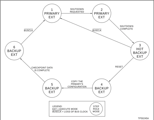
Primary Cycle
The step numbers in this cycle correspond to the states of Fig-ure A-3. The state of the LEDs and the contents of the second module status byte are indicated in the left margin.
Primary Backup
n n+1
01xx0x0x 10xx1x0x
z
{z
5
1. The primary MFC is actively controlling the process. (This represents the same juncture as step 5 of the backup cycle).
Primary Backup
n+1 n
01xx0x0x 11xx1x0x
{
5
z
5
2. When the shutdown request is received from the backup MFC (Step 8 of the backup cycle), the primary MFC stops exe-cuting and removes the bus clock.
Primary Backup
n+1 n
01xx0x0x 01xx1x0x
{
5
z
5
3. The primary MFC is now acting as the hot backup. All the old configuration and block output information remains intact from when it is shut down in Step 2. If the new configuration is not operating as expected, the primary MFC, currently acting as the hot backup, can take control using the old configura-tion and block output informaconfigura-tion (returns to Step 1).
Primary Backup
n+1 n
00xx0x0x 00xx1x0x
{
5
{
5
4. Stopping and resetting the primary MFC, currently acting as the hot backup, tells it to get a copy of the new configura-tion (Step 9 of the backup cycle).
Primary Backup
n+1 n
10xx0x0x 00xx0x0x
z
z
{
z
5. When the new configuration has been copied, the backup MFC has completed its cycle, and is now serving as the pri-mary MFC. Primary Backup n+1 n 10xx0x0x 00xx0x0x {
z
z
z
6. After the checkpoint data is complete, the primary MFC is now serving as the backup MFC and is ready to take over the control process. The primary cycle is complete. (This repre-sents the same juncture as Step 11 of the backup cycle).
Figure A-3. Primary MFC Operation Cycle 1 PRIMARY EXT 2 PRIMARY EXT 6 BACKUP EXT SHUTDOW N REQUESTED 3 HOT BACKUP EXT 4 BACKUP EXT 5 BACKUP EXT COPY THE PRIMARY'S CONFIGURATION STEP ROLE MODE LEGEND:
EXT = EXECUTE MODE BUSCLK = LOSS OF BUS CLOCK
TP50245A CHECKPOINT DATA IS COMPLETE BUSCLK BUSCLK SHUTDOW N COMPLETE RESET