Demand Control Ventilation
Application Guide for Consulting
Engineers
Rev. 3, August, 2013
Notice
Document information is subject to change without notice by Siemens Industry, Inc. Companies, names, and various data used in examples are fictitious unless otherwise noted. No part of this document may be reproduced or transmitted in any form or by any means, electronic or mechanical, for any purpose, without the express written permission of Siemens Industry, Inc.
All software described in this document is furnished under a license agreement and may be used or copied only in accordance with license terms.
For further information, contact your nearest Siemens Industry, Inc. representative. Copyright 2013 by Siemens Industry, Inc.
TO THE READER
Your feedback is important to us. If you have comments about this manual, please submit them to
APOGEE and Insight are registered trademarks of Siemens Industry, Inc.
Other product or company names mentioned herein may be the trademarks of their respective owners. Printed in the USA
Table of Contents
About this Application Guide ... I Goal of this Guide ... I How this Guide is Organized ... I Symbols ... II Getting Help ... II Where to Send Comments ... II
Chapter 1 – Introduction to IAQ and Ventilation Control ... 1
Background Information and Resources ... 1
IEQ versus IAQ ... 2
Role of Ventilation in IAQ ... 3
Role of Exhaust Air in Ventilation ... 3
Interior Design Component of Ventilation ... 3
Role of Population in Ventilation ... 4
Role of Outside Air in Ventilation ... 5
Role of Control in Ventilation ... 5
Determining Ventilation Volume ... 5
Relationship between Population and Ventilation ... 6
Relationship between CO2 and Ventilation ... 6
Zone Population Sensing Technologies for DCV Strategies ... 7
Relationship Between Building Pressurization and IAQ ... 9
Systems Serving Multiple Spaces ... 11
Ventilation Rates and Requirements ... 11
Codes and Standards... 11
Ventilation Rates ... 13
DCV Savings Opportunity ... 15
DCV Sequences Overview ... 21
Sensor Locations ... 21
Picking Zones ... 21
Zone Control vs. Central Control of Outside Air Intake ... 22
Combination: Zone CO2 Sensing with Central Control of Outside Air Intake ... 22
Combination: Zone Control with Design Ventilation at Central System ... 22
Combination: Zone Control and Central Control Combination ... 23
Combination: Zone Control and Central Control Working Together ... 23
Air-side Economizers and Ventilation Overrides ... 23
Use of a Purge Cycle ... 24
Methods of Controlling Building Pressure ... 25
Controlling Outside Air Intake ... 26
Old (Discredited) Approach: Minimum OA Damper Setting ... 26
Standard Approach: Fan Tracking ... 26
Improved Method: Direct Measurement ... 27
Improved Method: Plenum Pressure Control ... 27
General Resources on IAQ, DCV and Their Relationship to LEED ... 28
Chapter 2 – Concept and Sequence of Operation ... 29
Description of the Ventilation for Acceptable Indoor Air Quality (VAIAQ) Sequence 29 Explanation of VAIAQ Features ... 30
Minimum Ventilation ... 30
Free Cooling ... 31
Demand Controlled Ventilation ... 31
Building Pressurization ... 31
Purge ... 32
Sequence of Operation ... 32
Zone Control Application for DCV ... 34
Description of Zone Control Application for DCV ... 34
Chapter 3 – Designing a Central DCV System ... 39
Setting Outside Airflow Levels ... 39
Required Measurement of Outside Airflow ... 40
Designing Minimum Outside Air Control ... 41
Setting Purge Control Points ... 41
Coordinating Terminal Controls with the Air Handler ... 42
Determining VAV Box Minimum Settings ... 42
Determining Outside Air CO2 ... 43
Locating Zone CO2 Sensors ... 43
CO2-based DCV: Duct Versus Wall-Mounted CO2 Sensors ... 44
Location of Wall-Mounted CO2 Sensors ... 44
One Sensor vs. Multiple Sensors ... 44
Recommended Zone CO2 Sensor ... 45
Setting DCV Control Points ... 46
Calculating Zone Ventilation Requirements ... 47
Chapter 4 – Implementing, Troubleshooting and Maintaining a Central DCV System51 Setting Up CO2 Sensors ... 51
Setting Up Building Pressurization ... 51
Scheduling Purge ... 52
Setting up Minimum Outside Air Control ... 52
Troubleshooting ... 54
Technical Data ... 57
Features/Functions/Benefits ... 58
Glossary ... 61
About this Application Guide
This section discusses: The Goal of this Guide How this Guide is Organized
It also provides information on conventions and symbols used, how to access help, and where to direct comments about this application guide.
Goal of this Guide
The goal for this application guide is to give the reader the benefit of the company’s significant experience in Demand Control Ventilation (DCV) projects. Information and guidance here is based on those past success and challenges. It is assumed that the reader is familiar with building automation products and systems from Siemens Industry, Inc.
How this Guide is Organized
This application guide contains the following chapters:
Chapter 1 - Introduction to IAQ and Ventilation Control, presents background information on Indoor Air Quality and ventilation control that applies to many ventilation control systems.
Chapter 2 - Concept and Sequence of Operation, includes information specific to the ventilation control application presented in this guide. It tells how the application works and why it works that way.
Chapter 3 - Designing a Central DCV System, describes the tasks carried out by the control design engineer applying this system.
Chapter 4 - Implementing, Troubleshooting and Maintaining a Central DCV System, describes tasks likely to be carried out on the job site as the system is started up. Appendix A - Series 2200 Three-in-one Room Unit Technical Data and Features The Glossary describes the terms and acronyms used in this guide.
Symbols
The following table lists the symbols that may be used in this application guide to draw your attention to important information.
Notation Symbol Meaning
WARNING: Indicates that personal injury or loss of life may occur to the user if a procedure is not performed as specified.
CAUTION: Indicates that equipment damage, or loss of data may occur if the user does not follow a procedure as specified.
Note Provides additional information or helpful hints that need to be brought to the reader's attention.
Tip Suggests alternative methods or shortcuts that may not be obvious, but can help the user better understand the capabilities of the product, service, or solution.
Getting Help
For more information about Demand Control Ventilation (DVC), contact your local Siemens Representative.
Where to Send Comments
Your feedback is important to us. If you have comments about this manual, please submit them to: [email protected]
Chapter 1 – Introduction to IAQ and
Ventilation Control
Chapter 1 presents background information that applies to many ventilation control systems, not just to the application covered in this guide. It includes information on the following topics:
Background on IAQ and ventilation control Ventilation rates and requirements
DCV opportunities
Central DCV vs. Zone-level DCV Use of a purge cycle
Methods of controlling building pressure Controlling outside air intake
Background Information and Resources
IAQ inside buildings is the result of a combination of many variables. Some include: Materials used in construction
Contaminants that exist in the local ambient air Gases effused from the ground the building is built on Chemicals and equipment that are brought into the building Filtering methods
Human off gassing
Ventilation effectiveness
All of these factors, and more, are taken into consideration when designing a building. After the building is in operation, proper management draws on a broad range of disciplines to maintain adequate IAQ. Most of the IAQ is managed by the maintenance and operations of the building. Methods to manage good IAQ include:
Storing and using cleaning agents correctly Handling and removing trash effectively Maintaining ventilation filters
Seeking out and mitigating sources of long term moisture Operating a ventilation system according to design
There are many useful resources that cover IAQ more broadly. These resources discuss, among other issues, the sources of air contaminants and how to control them. They provide guidance for questions like the following:
How are cleaning chemicals stored?
Where does the garbage sit before it is taken out? Are the air intakes clean?
Some of these documents, and tools that IAQ designers can use to improve IAQ, can be obtained from the U.S. Environmental Protection Agency. Here are some Web sites from the U.S. EPA that may be useful at the time of this writing:
For green buildings: http://www.epa.gov/greenbuilding/index.htm For large buildings: http://www.epa.gov/iaq/largebldgs/index.html IAQ design tools for schools: http://www.epa.gov/iaq/schooldesign/ IAQ tools for schools: http://www.epa.gov/iaq/schools/index.html Molds and moisture: http://www.epa.gov/mold/index.html
Second-hand smoke and going smoke-free: http://www.epa.gov/smokefree/ Another good source of information is ASHRAE Standard 62.1: Ventilation for Acceptable Indoor Air Quality, which describes the ventilation requirements related to IAQ. However, it does not address other aspects of IAQ or ventilation. Use this, along with applicable building codes and the customer’s own standards, to determine ventilation requirements.
IEQ versus IAQ
The terms indoor environmental quality (IEQ) and indoor air quality (IAQ) are often
mistakenly interchanged. The differences are subtle, but worth understanding. IEQ refers to the overall environment and all parameters that affect the occupants, such as temperature, humidity, lighting, noise, controllability, safety and others. IEQ includes IAQ.
IAQ is more specifically defined as “a function of the interaction of contaminant sources and the effectiveness of ventilation utilized to dilute and remove air contaminants” (Bearg 2008). It is physically impossible to eliminate all sources of air contaminants. Even outdoors, a considerable amount of air contaminants exist. The process to manage IAQ inside buildings is first to minimize the sources, then exhaust known unavoidable sources, then dilute the rest of the air to mitigate build up of contaminants1.
This document focuses on the dilution part of the building IAQ process. In ASHRAE 62.1-2010, it is referred to as Ventilation requirements and a method called Demand Control Ventilation.
1
Measuring IAQ Parameters HPAC Engineering, Aug 1, 2008 12:00 PM, By DAVID W. BEARG, PE, CIH Life Energy Associates Concord, Mass.
Role of Ventilation in IAQ
Ventilation is one part of the overall process to maintain IAQ in a commercial or institutional building. In a building, contaminants build up over time. Some contaminants come from outside, some come from inside and some come from the occupants. The primary goal of ventilation is to reduce airborne contaminants by diluting indoor air, which has a higher concentration of contaminants, with outdoor air that has less contaminant.
Role of Exhaust Air in Ventilation
The first parameter that a design engineer evaluates is how much exhaust is needed for the special spaces that cause low IAQ. These are the spaces that are needed for a normal operation of a building and cannot be avoided. As long as they are well defined and designed, they can be handled in an efficient way. Some of the spaces in commercial buildings that require special exhaust handling include:
Trash rooms
Kitchen or pantry exhaust Copy room exhaust Bathroom exhaust
Other spaces often have special exhaust systems that may be there to handle high temperature loads, and not necessarily IAQ, for instance:
Computer rooms Electrical closets
Some buildings by design have special exhaust or ventilation needs above and beyond the typical commercial building design, such as:
Labs
Healthcare facilities
Pools and pool water treatment rooms Indoor garages
Special standards and codes are written for these types of environments and an experienced consultant should be retained for designing systems for these facilities.
Interior Design Component of Ventilation
Some contaminants are from the building. Many materials used in construction give off gasses that negatively impact the health and comfort of occupants. These gasses are called effluents. More specifically, they are referred to as Volatile Organic Compounds (VOC). Materials that give off measurable amounts of VOCs include:
Paint Carpet
Plastics in furniture Computers Plants
These materials emit a high level of VOCs when they are new. That is why it is often
noticeable when a building is newly constructed, renovated or even painted. These materials continuously emit VOCs. Over time, the rate of emitting VOCs in most materials decline with age. The rate of emitting VOCs drops dramatically over the first few weeks of use or
installation. Then over the first few years, the emitting rate continues to drop to a lower level. Eventually, it drops to a consistent rate. That is why guidelines are written to purge new construction buildings in order to eliminate the highest concentration of VOCs and some guidelines call for increasing ventilation for a year or two.
Many of these materials are now becoming available in low-emitting versions. Even so, the design engineer must design an amount of ventilation to dilute the anticipated VOC levels. Most jurisdictions and professionals reference ASHRAE Standard 62.1 to determine the amount of ventilation needed for dilution of the Interior Design Component.
In the ASHRAE 62.1 standard, table 6-1 defines a factor called “Area Outdoor Air Rate (Ra)”.
There are a variety of values that correspond to different types of spaces. The values guide the engineer to a ventilation rate per square foot of space. The design engineer can also, at his discretion, add design factors for special cases, such as high concentration of painted walls, high concentration of computers, or high concentration of art materials such as architects or designers offices. The design engineer cumulates the ventilation rates for all of the spaces to determine a ventilation rate for the area.
Role of Population in Ventilation
Humans are another source of contaminants. Ventilation is intended to dilute odorous bioeffluents from occupants and other sensory contaminants that result directly from
occupant activities. It is proportional to the number of people expected to occupy the space. These include:
Metabolic odors
Odors from clothes, shoes and coats
Odors from lotions, perfumes and hair products Food odors
Machines that humans use, such as copiers and printers
Up until 1999, the guidelines for ventilation were to predict the normal population of a building. More specifically, the design engineer anticipated the normal or maximum
population of each space and added them up. This often resulted in highly ventilated spaces. This was not a problem for IAQ, but the cost of the ventilation was higher than it needed to be.
In 1999, an updated version of ASHRAE 62.1 was issued that allowed for changing ventilation base on predictable or sensed changes in population. Thus, the ventilation rate could change based on the demand. This is the establishment of Demand Control Ventilation. Further refinements to DCV methods were issued in 2001, 2004, 2007 and 2010.
Role of Outside Air in Ventilation
Fresh air from outside the building is the media used to dilute contaminants inside buildings. The whole process of diluting contaminants is ventilation. Outside air intake flow is one important component of ventilation, but it includes much more.
Ventilation includes the entire process of air delivery and air removal for a space. This process includes outside air intake, mixing, delivery through the duct system, the air
terminals, and diffusion through the space. Ventilation also includes the mixing processes in the space, and the entire exhaust process. A system has to function correctly all the way through the process to effectively ventilate a space. While outside air intake is one of the many challenging and crucial steps in this process, it is not the whole process of ventilation.
“Outdoor Air” and “Ventilation Air”
The terms outdoor air and ventilation air are often used interchangeably. There is an
important distinction between them. Outdoor air—also called intake air, fresh air or first pass air—describes air brought into the building from the outdoors. Ventilation air is typically a mixture of outdoor and recirculated air used to dilute contaminants within a building’s occupied spaces.
Role of Control in Ventilation
Proper control function is another necessary aspect of ventilation. The control system coordinates all of the moving parts that must work together to achieve the intended
ventilation. Controls sense conditions, move dampers, speed fans up and down and switch between operating modes. Control includes setting the right mix of outside air in the supply air, balancing the flows in and out of the building, and supplying the right flow rate to each zone. If all of these controls operate correctly, it is possible to achieve proper ventilation. However, proper control cannot overcome a ventilation system that is inadequate in other ways. Control functions do not compensate for poor air diffusion, inappropriate contaminant sources in the space, mold in the ventilation equipment, or outside air intakes that draw contaminated air.
Determining Ventilation Volume
The volume of ventilation that must be designed for a building is codified. It is up to the Professional Engineer to design for the amount needed to meet codes and other guidelines. Previously, the document names several resources that are referred to for special
applications. For Ventilation, the most common reference is ASHRAE 62.1 – Ventilation for Acceptable Indoor Air Quality.
Since 2004, ASHRAE has prescribed a two-step calculation for determining the amount of ventilation needed for a common building space. One step is square footage of building space and second step is human population. These two components added together result in the amount of dilution air that must be delivered to the occupied spaces.
If exhaust air for special applications exceeds the amount of outside air intake normally needed for ventilation, or if there is a great amount of exhaust air needed for one area of a building, then the ventilation system must be designed to replace that air, in addition to the diluted air needed for the occupied spaces.
Relationship between Population and Ventilation
Human bioeffluents is one of the contaminants that must be diluted in order to maintain a comfortable and healthy indoor environment. Bioeffluents increase with the density of the occupancy. Bioeffluents also increase in proportion to the activity of the occupants. The ventilation system must be sized to handle the worst expected case of bioeffluent build up. It is based upon the full design occupancy of the building and the expected activities of all occupants. Often, additional ventilation is designed to account for spaces where occupants in a building gather in high density for temporary activities, such as conference rooms,
cafeterias, exercise rooms, classrooms, etc. This sizing activity determines the design ventilation amount for the building.
Relationship between CO
2and Ventilation
Humans are a source of contamination of air inside buildings. Humans and the activities they perform lead to odors that can be sensed by others. When 80% of the occupants perceive the air to be free from annoying odors, then the air is generally deemed acceptable. Diluting the human component of contamination is important for IAQ. Typically, the engineer
anticipates a design population and sizes the ventilation system to always dilute for that amount of people. A more energy efficient way to ventilate would be to measure the amount of people who occupy a space on a real-time basis and only ventilate for that measured or calculated amount. This is called Demand Control Ventilation (DCV).
In order to ventilate for human contamination via DCV, engineers must be able to predict, calculate or measure the population changes in the building over time, and understand where that population occupies. Humans exhaust CO2 at predictable, but varying, rates depending on the activity they are performing. The increase in levels of CO2 inside a building is
correlated to the population inside the building, assuming there is not another source of CO2. CO2 is a convenient and easy gas to measure. It exists naturally in ambient air. Relatively inexpensive sensors can measure the CO2 level in the air. CO2 sensing is a convenient indicator of the relative amount of people that occupy a zone inside a building. As the increase population is sensed, the ventilation requirements go up.
When considering the relationship between CO2 and ventilation, the most important point to
understand is that CO2 is not considered an air contaminant at the concentrations commonly
found in most buildings (400 – 3000 ppm). There are no health implications of CO2 in
concentrations below several thousand parts per million (ppm). However, in concentrations at or just below about 3000 ppm, people start to feel tired and listless, many complain of
“stuffiness” or being “warm” in the room, and they have trouble concentrating. The
Occupational Safety and Health Administration(OSHA) lists 5000 ppm as the threshold limit value for a time-weighted average over five 8-hour workdays and the American Conference of Governmental Industrial Hygienists lists 30,000 ppm as the 15-minute exposure limit. There is also no evidence that CO2 causes discomfort or dissatisfaction at the levels found in
most buildings.
When implementing a Demand Controlled Ventilation (DCV) system based on CO2 sensing,
CO2 control is a method, not a goal. The goal is to dilute the bioeffluents from the human
population. Research has shown that there is a corresponding relationship between the rate that bioeffluents are emitted and CO2 is exhaled. Because of this relationship, CO2 can be
used as a tracer gas to determine the rate of bioeffluent accumulation. If the increase in CO2
above normal can be measured, then CO2 can be used as a means to determine when
The CO2 concentration is directly related to the amount of other human contaminants that
need to be diluted. Therefore, CO2 concentration correlates to ventilation per person, which is proportional to the bioeffluent IAQ parameter. To understand how CO2 relates to
ventilation, consider where the gas comes from, and where it goes in the indoor air. 1. Human respiration is the primary source of CO2 in most indoor spaces. With every
breath, people add a CO2 to the mix of gasses in the air. The rate at which people
generate CO2 depends on how many people are there, what they are doing, and other
physiological factors.
2. Ventilation is the primary mechanism for removing CO2 from most indoor spaces. The
CO2 sources in an enclosed space add to the concentration inside, so it rises above the
concentration outside. A ventilation process that brings in outside air (low CO2
concentration) and removes room air (high CO2 concentration) removes CO2 and other
human contaminants from the ventilated space. The removal rate depends on the mix of outdoor air and recirculated air in the ventilation air, the CO2 generation rate within the
space, and the difference in CO2 concentration between inside and out.
3. The generation and removal of CO2 proceed at their own rates, dynamically increasing or
decreasing the CO2 concentration in the space. When they balance, the CO2
concentration reaches a steady value. At this point, it is possible to relate the ventilation rate to the occupancy of the space if you know the difference between the CO2
concentrations inside and out, and the average rate that the occupants generate CO2.
(See Equation (3) in Chapter 2 under the heading Determining the Zone Population.) The dynamics of the CO2 concentration reinforces its use as a ventilation indicator. Consider
a room at a steady CO2 concentration. When the activity in the room changes—either more
people enter or they become more active—more CO2 is generated at a higher constant rate.
The imbalance between the higher generation rate and the original removal rate adds CO2 to
the room. The concentration increases gradually, and continues to increase until the dilution rate catches up with the generation rate. Eventually, the system stabilizes at a higher CO2
concentration. This is usually a slow process, similar to a room temperature response. The time to complete the CO2 change is related to the ventilation air change rate of the room and
can range from several hours to about 15 minutes.
The Indoor Air Quality Guide: Best Practices for Design, Construction and Commissioning is designed for architects, design engineers, contractors, commissioning agents, and all other professionals concerned with indoor air quality. It is a best practices guide developed jointly by ASHRAE, the American Institute of Architects (AIA), Building Owners and Managers Association (BOMA), Sheet Metal and Air Conditioning Contractors National Association (SMACNA), the U.S. EPA and USGBC. This guide is available for purchase at the following Web address: http://www.ashrae.org/resources--publications/bookstore/indoor-air-quality-guide.
Zone Population Sensing Technologies for DCV Strategies
When most people think of implementing a DCV strategy, they think that CO2 sensing in the
space will automatically be required. However, there are many zone types where CO2
sensing may not be the best choice. CO2 sensors are subject to calibration drift and accuracy
issues over time; they require proper periodic maintenance (for example, cleaning and re-calibration). If this maintenance is not performed, or not performed in a timely manner, there is some risk involved in keeping the reporting of CO2 accurate over time. Other technologies
Time-of-day schedules Occupancy (on/off) sensors People counters
CO2 sensors
Time-of-Day Schedules
There are some zone types, such as school cafeterias or university or high school lecture halls, where a pretty accurate estimate of the daily zone population pattern can be obtained from simply using a time-of-day schedule. For example, in the case of a university lecture hall, it is typically known how many students are registered for a given lecture and the schedule of that lecture (that is, what hours of each day the lecture will be conducted). In this case, ventilation can be supplied to the zone at the level to meet the needs of all the
registered students for that lecture at the hours it occurs, then reduced to minimum for other hours, or shut off entirely when unoccupied2.
Occupancy Sensors
Occupancy sensors that detect whether there are people in the zone or not can also be used for certain zone types as an indicator of the approximate population in that zone. Examples of zones where occupancy sensors can be used to detect population when implementing a DCV strategy are private offices and smallconference rooms. For example, when the occupancy sensor detects a private office is occupied, ventilation can be provided to the zone that is adequate for one person, then reduced to minimum when the occupant leaves the room, or shut off entirely when unoccupied3. In the case of a small conference room, when the occupancy sensor detects that there are people in the room, ventilation can be supplied to the conference room at the level to meet the needs of the maximum number of people likely to be meeting, then reduced to minimum for other hours, or shut off entirely when
unoccupied4.
People Counters
Infra-red or light beam sensor technology to count the number of people in a building space or the number of people that pass through a door does exist but, compared to occupancy sensors, are seldom used for implementing a DCV strategy. However, for certain space types, such as theaters and labs, accurate methods of counting the people occupying a space inside the building do exist. For example, in theaters, the “point of sale” (that is, the number of tickets sold) can be an accurate indicator of the number of people in that zone, and spaces that have card-access systems, such as labs, can also be used to indicate the number of people in that zone.
2
We shall see that ASHRAE Standard 62.1-2010 permits shutting off the ventilation to a zone only during unoccupied hours when no one is in the zone. During normally occupied hours, if there is no one in the zone, ventilation can be reduced to meet the “floor area” (
R
a
A
z) component of the ventilation requirement.CO
2Sensors
According to Emmerich and Persily (1997)5, CO2-based DCV is most likely to be
cost-effective when there are unpredictable variations in occupancy in a building and climate where heating and cooling is required for most of the year, and when there are low pollutant emissions from non-occupant sources6. The advantage of CO2 -based DCV is if the CO2
sensors are kept properly maintained and calibrated, accurate measurements of zone and outside air can be measured and Equations (3) and (4) can be used to accurately calculate the people in the zone, and the zone differential CO2 setpoint (difference between the zone
and outside air CO2 concentrations), respectively, and ventilation can be provided to meet the
exact requirements.
Relationship between Building Pressurization and IAQ
Building pressurization is an area of study by itself, and it is tightly linked to outside air intake and exhaust. The three parameters are inter-related so sequences need to address each. The three parameters are inseparable because of the following:
The same components affect both variables. Outside airflow and building pressure are both affected by the operation of both fans and by the dampers in the mixing section. A change at any one of those components can be seen in the outside air intake and in the building pressure. (In fact, Fan Flow Tracking, a well known building pressurization strategy, is often proposed as a strategy for outside air intake control.) Building pressurization is the balance between intake and exhaust, so outside air
intake is half of the building pressure phenomenon. One way a building
pressurization system can fail is when the outside air intake goes to a value too high or too low for the exhaust system to track.
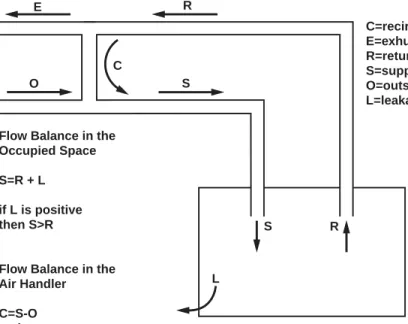
Improper building pressurization leads to unplanned outside air intake. If the return flow is outside the proper range, the building draws uncontrolled outside air, either by infiltration in the space, or by reverse flow at the exhaust damper. Either way, the unplanned flow defeats whatever outside air intake control has been achieved. Figure 1 illustrates the effect of inaccurate building pressurization.
5
Emmerich, Steven J. and Persily, Andrew K., PhD. 1997. Literature review on CO2-based
demand-controlled ventilation, ASHRAE Transactions, 103(2).
6
E O R S C S R L Flow Balance in the
Occupied Space S=R + L
if L is positive then S>R
Flow Balance in the Air Handler C=S-O and C=R-E so S-O=R - E if E is positive R>S - O
Combine the Constraints to keep L positive (Bulding leaks out) and E positive (no back flow at ex.) S>R>S-O
Return flow must be less than supply but greater then supply minus OA Limits On Return Flow For Proper
System Balance C=recirculation E=exhust R=return S=supply O=outside L=leakage HV A C0456R1
Figure 1. Limits on Return Flow for Proper System Balance.
Building pressurization has still more affects on IAQ. Negative building pressure causes infiltration of outside air into the occupied spaces. While outside airflow is generally good for IAQ, and infiltration is sometimes viewed as another source of ventilation air, there are also problems associated with infiltration. Common problems include the following:
Infiltration brings in untreated air and can cause uncomfortable conditions in the occupied spaces, which then affects people’s perception of air quality.
Humid infiltrating air can lead to mold and degradation of the building envelope. The effect in the occupied space is bad, but moisture deposited within the walls can be a disaster for IAQ and for the structure.
Infiltrating air may be contaminated. Outside air intakes are supposed to be engineered to avoid the worst outside air, but this is impossible with infiltration. The importance of these effects varies. For some buildings in cold climates, the situation is reversed. In those buildings, positive pressure drives moist indoor air into the envelope. The condensation then freezes and damages the structure. In this situation, the design engineers may decide that negative pressure is preferred.
Systems Serving Multiple Spaces
In a typical air distribution system, one air handler serves multiple terminals. Each terminal serves a particular room, or group of rooms, or part of a room. The separate rooms may be viewed as individual spaces with their individual outside airflow requirements. The central air handler has to draw enough outside airflow to satisfy all the spaces, but it can't individually deliver the required outside air quantity to each room. The outside air comes in and gets mixed with the return air, making it impossible to deliver a precise outside air quantity to a specific room.
If the outside airflow at the air handler is the sum of the requirements in each space, some spaces will get more outside air than they need and some will get less. If the outside air fraction for the air handler is set equal to the highest outside air fraction needed by any space, then they all get at least the minimum amount of outside air, but the system may use a lot of outside air and a lot of energy to treat it.
The ASHRAE Standard 62.1-2010 defines a middle ground between these two, reducing outside airflow as far as possible while maintaining the required outside airflow to each space. Follow the procedures in section 6.2.5 of ASHRAE 62.1-2010 to calculate the amount of outside air ventilation required for each zone of a multi-zone system. For each zone, a zone air distribution effectiveness factor, Ez, and a system ventilation efficiencyEv must be determined from using Tables 6-2 and 6-3, respectively, or use Appendix A for the
determination of Ev.
A DDC control program with a Demand Control Ventilation strategy can be applied to multi-zone systems provided the following conditions are met:
Airflow to each zone is controlled by separate VAV boxes.
There is a method to determine change in occupancy for each zone.
The outside air ventilation requirement is calculated for each zone, taking into account the zone air distribution effectiveness (Ez) and the system ventilation efficiency (Ev) according to ASHRAE 62.1-2010.
The max VAV box airflow is set up to provide the ventilation required when the zone is at maximum occupancy.
Ventilation Rates and Requirements
The following sections discuss the codes, standards and ventilation rate values you need to know when setting up a DCV system.
Codes and Standards
The required ventilation rates are among the most basic design parameters for any HVAC design or retrofit. ASHRAE Standard 62.1: Ventilation for Acceptable Indoor Air Quality is probably the most referenced standard by jurisdictions and design professionals. (This standard is updated by ASHRAE every 3 to 4 years, the version number being designated by the year of the update after the number of the standard. For example, at the time of this writing, ASHRAE Standard 62.1-2010 is the latest version of the standard.)
Ventilation rates are set by local building codes, building standards, ASHRAE Standard 62.1, or a combination of the three, but local building codes usually have jurisdictional priority. In the New York City area in the U.S., local building codes do call for the use of ASHRAE Standards 90.1 and 62.1 for all new construction projects, and major renovation projects for existing buildings. Although, the use of ASHRAE Standards 90.1 and 62.1 in local building codes is prevalent throughout the U.S. for new construction and major renovation projects, it is certainly not universal, especially in more rural areas. If you are involved in setting the rates, you need to choose the highest value from all of those sources. If you are not involved in setting the rates, get explicit written instruction on what the rates are and who has taken responsibility for them.
Many building codes use the International Mechanical Code (IMC) as a model.
Representatives of the International Code Council have managed this document since 2003. The IMC uses ASHRAE's Standard 62.1 table of ventilation rates for various types of spaces (Table 6-1). An excerpt of this table is shown later in this document.
Demand Control Ventilation and LEED
®Green Building Rating Systems
The primary reference for the design, construction, and operation of green buildings for the U.S. market is the U.S. Green Building Council’s Leadership in Energy and Environmental Design (LEED®) program. A companion organization called the Green Building Certification Institute (GBCI) is responsible for rating buildings according to green building design, construction and operation standards, and accrediting professionals. A Demand Control Ventilation operating strategy can play a prominent or supporting role in several LEED® prerequisites or credits according to the LEED 2009 Green Building Operations and Maintenance and the LEED 2009 Building Design and Construction Reference Guides. In the IEQ section of the LEED 2009 New Construction and Major Renovation rating system, the designer is required to meet the requirements of Sections 4-7 of ASHRAE 62.1-2007, Ventilation for Acceptable Indoor Air Quality.
Although CO2 monitoring is not a prerequisite, they do offer an optional Credit (IEQ C1). The
credit calls for permanent monitoring of ventilation and notifying an operator when the ventilation deviates from design by more than 10%. Monitoring systems can use airflow values or CO2 levels. The credit also requires that CO2 be monitored in densely populated
zones, such as classrooms, conference rooms and training rooms.
In the EA section of LEED 2009-NC, the designer is required to exceed the baseline energy performance of ASHRAE 90.1-2007. Part of the baseline requirements is to apply DCV to high occupancy spaces, with a few exceptions.
Overlapping investment can provide more benefits. DCV does not require that CO2 sensing
be used, but, if CO2 sensing is used, it contributes to the Energy prerequisite (EA PC1) and to
the IEQ optional credit (IEA C1).
Likewise, if more zones are monitored under the IEQ C1 using CO2 sensors, then all of those
zones can easily be converted to DCV sequences and possible contribute to more EA optional points for higher energy efficiency.
The LEED 2009 Existing Buildings Operations & Maintenance rating system has similar credits in IEQ and EA that can be supported by DCV and CO2 monitoring.
Ventilation Rates
The following values are needed to design a demand controlled ventilation system: Exhaust and Exfiltration Rate – the flow required to pressurize the building. Most buildings have exhaust fans that are separate from the air handler. Examples include exhaust fans for restrooms, kitchens and photocopy rooms. The outside airflow must be enough to balance all the exhaust devices, plus enough to generate the desired exfiltration to the surrounding spaces, including the outdoors. Building pressure is usually controlled through modulation of the return flow, exhaust flow or relief flow, but control of building pressure is only possible if the outside airflow is large enough to balance exhaust and exfiltration.
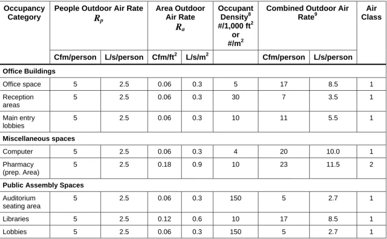
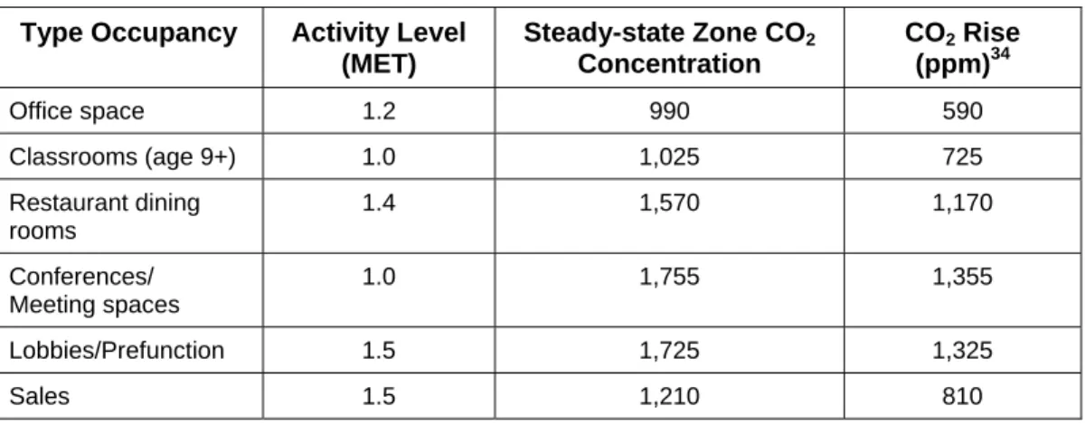
Design Ventilation Rate – the flow required at full occupancy. This value should be calculated using Table 6-1 in ASHRAE Standard 62.1-2010 (this table is reproduced, in part, as
Table 1 in this document). For most types of spaces, the ventilation requirements are expressed in cfm (L/s) per person for the people component and cfm/ft2 (L/s/m2) for the building component. To set the rate, characterize the use of the space and determine the design occupancy by getting the customer's estimate of the number of occupants expected and the floor area of the space. Table 6-1 of ASHRAE Standard 62.1-2010 lists default occupancies (in number of people per 1000 ft2 or per 1000 m2) for many types of spaces. The IMC prohibits using an occupancy number less than ASHRAE's estimate without "approved statistical data".
Minimum Ventilation Rate – Table 6-1 in ASHRAE Standard 62.1-2010 specifies a minimum ventilation rate based on both the number of people in a space and for the effluents generated within the space. This minimum ventilation rate is specified according to the following equation:
z a z p bz
R
P
R
A
V
(1) [Eqn. (6-1) in ASHRAE 62.1-2010] Where:Vbz = the breathing zone outdoor airflow, cfm (L/s).
Rp= Outdoor airflow rate (cfm, L/s) required per person as specified in Table 6-1. These values are based on adapted occupants (occupants adapted to the zone environmental conditions).
Pz= Zone population: the largest number of people expected to occupy the zone
during typical usage. If the number of people expected to occupy the zone fluctuates, Pz may be estimated based on averaging approaches described in Section 6.2.6.2.
If Pz cannot be accurately predicted during design, it shall be an estimated value based on the zone floor area and the default occupant density listed in Table 6-1.
Ra = Outdoor airflow rate (cfm, L/s) required per unit floor area (ft2, m2) as specified in
Table 6-1.
Table 1. Selected Outdoor Air Requirements for Ventilation.7
Occupancy Category
People Outdoor Air Rate
Rp
Area Outdoor Air RateR
a Occupant Density8 #/1,000 ft2 or #/m2Combined Outdoor Air Rate9
Air Class
Cfm/person L/s/person Cfm/ft2 L/s/m2 Cfm/person L/s/person
Office Buildings Office space 5 2.5 0.06 0.3 5 17 8.5 1 Reception areas 5 2.5 0.06 0.3 30 7 3.5 1 Main entry lobbies 5 2.5 0.06 0.3 10 11 5.5 1 Miscellaneous spaces Computer 5 2.5 0.06 0.3 4 20 10.0 1 Pharmacy (prep. Area) 5 2.5 0.18 0.9 10 23 11.5 2
Public Assembly Spaces
Auditorium seating area
5 2.5 0.06 0.3 150 5 2.7 1
Libraries 5 2.5 0.12 0.6 10 17 8.5 1
Lobbies 5 2.5 0.06 0.3 150 5 2.7 1
In a multi-zone system, the Equation 1 above is applied to each zone individually. The zone terminal unit is set up to meet the requirements of the zone. The AHU that feeds the zone terminal units has to provide enough ventilation air to meet the accumulated ventilation requirements for all of the zones.
DCV is meant to reduce the human component of the fresh air ventilation requirements when fewer than the design number of people are occupying a space during occupied hours. The fresh air ventilation requirements to dilute the building effluent component should be regarded as the low limit of the fresh air ventilation when there are no occupants within the space during occupied hours.
7
DCV Savings Opportunity
The primary purpose of DCV is to save energy, not to improve IAQ. In fact, the IAQ can either improve or worsen, depending on the baseline ventilation rate. For example, the LEED 2009 Green Building Design and Construction (IEQ Credit 2) and LEED 2009 Green Building Operations and Maintenance (IEQ Credit 1.3) reference guides specifies that IAQ will improve if outdoor air ventilation rates for all air handling units serving occupied spaces can be increased by at least 30% above the minimum required by ASHRAE Standard 62.1. One point is awarded in each rating system if it can be shown that the above outdoor airflow rates at met.
Ventilation rates affect the cost of operating a building. When outside air is brought in for the sake of IAQ, the system consumes energy to condition that air. The more outside air is required, the greater the energy expense. This motivates some customers and HVAC engineers to reduce that expense if possible, as long as they can continue to meet codes. ASHRAE Standard 62.1, the IMC, and some local codes specify most ventilation rates in terms of the number of occupants. As people come and go, the number of occupants in a particular space varies. This suggests that the ventilation rate could go up and down with the occupancy. Demand Controlled Ventilation means just that: when the space is full, ventilate at the highest rate required. When the space is less occupied, reduce ventilation to
correspond to the number of occupants at the time.
ASHRAE Standard 62.1 has been officially interpreted to support that concept. The IMC specifically says the system must be designed to ventilate at the maximum expected occupancy, but may be operated according to actual occupancy at the time. Both of these documents support the concept of DCV, in which the ventilation rate is varied to meet changing occupancy. Local codes may not address the question. Consider getting a local ruling before designing a DCV system since local building codes usually hold jurisdictional standing.
Compared to a system that ventilates at the design rate all the time, a DCV system can save significant amounts of energy (documented studies show up to 70% savings for some zone types and occupancy variations). The savings, however, varies in different buildings. Factors include the following:
The occupancy pattern – a system with many operating hours at low occupancy offers a greater opportunity than one that usually either shuts off, or runs at full occupancy. A movie theatre is an example of a space where the occupancy varies greatly, while an office with workers on a uniform schedule is the other extreme. This kind of workplace is becoming less common. Many buildings now run evenings and weekends with light usage.
Weather – cities in Minnesota and Florida are likely to have higher expenses than a city like San Diego, and all other factors being equal, will make DCV less cost effective to implement. However, even cold or hot/humid climates have seasons when outside air is less expensive to use than re-circulated air.
The type of air distribution HVAC system used to heat and cool the building, and the price of energy.
On this last point, DCV is most feasibly implemented on Single-Zone (Supply)
Systems (constant volume reheat, single-duct VAV, single-fan dual duct, and multi-zone systems). On these systems, the calculations in Equations (6-1) through (6-8) in ASHRAE Standard 62.1-2010, and Equations (A-1) and (A-2) in Appendix A of that standard are fairly straightforward and can be performed in the controller program. DCV can also be
implemented in Dedicated Outdoor Air Systems (DOAS) and multi-zone recirculation (VAV) systems. Procedures are described in ASHRAE 62.1-2010 Sections 6.2.4 and 5. Excerpts are shown in Chapter 3 of this document. DCV can also be implemented in Secondary Recirculation Systems (such as dual-fan dual-duct, and fan-powered mixing box systems). However, the ASHRAE Standard 62.1 calculations and procedures needed to implement DCV are much more complex and are not described in this guide. Consult the ASHRAE Standard 62.1-2010 Appendix A and the User’s Manual for ASHRAE Standard 62.1-2010 for the equations and procedure necessary for implementing DCV for secondary recirculation systems.
Therefore, a DCV system is a typical energy conservation strategy and is most cost effective on single-supply systems for large spaces with variable occupancy, such as lecture halls, auditoriums, gymnasiums, but can be applied to smaller zones such as conference rooms, meeting rooms and class rooms (college or adult only – do NOT attempt to implement DCV for K – 12 schools since ASHRAE Standard 62.1 applies to body mass and metlevels for adults only). The HVAC engineer must estimate the annual savings before committing to a DCV system.
Paragraph 6.4.3.9 Ventilation Controls for High-Occupancy Areas in ASHRAE Standard 90.1-2010 states that DCV must be implemented for all spaces larger than 500 ft2and with a design occupancy for ventilation of greater than 40 people per 1000 ft2of floor area that has one or more of the following: (a) an air-side economizer, (b) automatic modulation control of the outdoor air damper, or (c) a design outdoor airflow greater than 3000 cfm. Note that there are four exceptions to this requirement:
1. Systems with exhaust air energy recovery complying with section 6.5.6.1 of ASHRAE Standard 90.1-2010.
2. Multiple-zone systems without DDC of individual zones communicating with a central control panel.
3. Systems with a design outdoor airflow less than 1200 cfm.
4. Spaces where the supply airflow rate minus any makeup or outgoing transfer air requirement is less than 1200 cfm.
Building and Zone Types Best Suited for CO
2-based DCV
According to Emmerich and Persily (1997)10, there is a fairly wide consensus on when to use CO2-based DCV. Most of the discussions of CO2-based DCV mention the following building
and zone types as good candidates for such control:
Public buildings, such as cinemas, theaters, and auditoriums Educational facilities such as classrooms and lecture halls Teaching labs
Retail establishments
CO2-based DCV is most likely to be effective where unpredictable variations exist in
occupancy for a building and climate where heating or cooling is required for most of the year, and low pollutant emissions from non-occupant sources exist. For predictable variations in occupancy, ventilation based on a time-of-day schedule is generally most cost-effective, while for small zones, such as small conference rooms or private offices, ventilation based on an occupancy sensor is often the most cost-effective approach.
Savings Potential with CO
2-based DCV
Numerous studies have documented the energy savings performance from CO2-based DCV.
Case studies based on both field tests and computer simulations show a wide variance in the energy savings potential of DCV.
A literature review of CO2-based DCV was performed by Emmerich and Persily (1997)11 that
included case studies based on both field tests and computer simulations, studies of sensor performance and location, and discussions of the application of the approach. Field test energy savings results included the following:
Many of the following field tests were early studies of CO2-based DCV when the
science of DCV was in its infancy. A significant shortcoming of many of these early studies was the inclusion of little or no description of the control algorithm investigated in the study. These omissions made it hard to evaluate which approaches worked, and which did not. In several of the studies cited below, the indoor air CO2
concentration was often not high enough for the CO2 control system to operate. This
may be due in part to the relatively low occupant density in office buildings. Also, many of these early studies cite the relationship of CO2 control with indoor air quality
(IAQ). As we have seen, IAQ is often more a matter of facilities management and indoor pollutant sources, such as the generation of Volatile Organic Compounds (VOC’s) from certain building materials, floorings, seals, and adhesives. DCV addresses ventilation only but ventilation is only one component of IAQ (refer to section on Error! Reference source not found.).
1. Two floors of an office building in Montreal, where one floor was equipped with a CO2-based DCV system while the other floor served as a control space (Donnini et
al. 1991; Haghighat and Donnini 1992).12,13Annual energy savings of 12% were measured for the floor with DCV. Occupants of the DCV floor complained
significantly more about the indoor environment than occupants of the control floor for part of the year.
11
Op. Cit. Footnote 5.
12
Donnini, G., F. Haghighat, and V.H. Hguyen. 1991. Ventilation control of indoor air quality, thermal comfort, and energy conservation by CO2 measurement. Proceedings of the 12th AIVC Conference Air Movement & Ventilation Control within Buildings, pp. 311 – 331. Coventry, U.K.: Air Infiltration and Ventilation Centre.
2. Another frequently cited study took place in a Minnesota high school (Janssen et al. 1982)14. The ventilation system used CO2 and temperature to control outdoor air and
had separate dampers for temperature and CO2 control. The measured energy
savings were about 20%. The occupant questionnaire showed that the subjects felt warmer with increased CO2 concentrations despite the fact that there was no
measurable temperature difference with and without CO2 control.
3. A study of two Finnish public buildings, one that had CO2-controlled ventilation,
included measurements of radon, particulates, and CO2 (Kummala et al. 1984) 15
. No description of the algorithm was reported. Daily energy savings were estimated to be 13% to 20%.
4. Auditoriums are good examples of ideal spaces for DCV because of their wide diversity in occupant density. One such study took place in an auditorium with CO2
and timer control of ventilation at the Swiss Federal Institute of Technology in Zurich (Fehlmann et al. 1993)16. The ventilation system had two stages of airflow capacity, with the first stage coming on at a CO2 concentration of 750 ppm and the second
stage coming on at a CO2 concentration of 1300 ppm. The second stage would turn
off at a CO2 concentration of 1100 ppm and the first stage would turn off at a CO2
concentration of 600 ppm. With ventilation controlled by CO2, run time was 67% of
the run time with timer control in summer and 75% in winter. Energy consumption with CO2 control was 80% less in summer and 30% less in winter.
The above study is an example where CO2 control saved on both fan (electric) energy
and coil (thermal) energy. In this case, fan electrical savings was due strictly to the control strategy of using a two-stage fan for CO2 control. Most DCV systems today
are implemented on systems with single-stage fans and so savings are derived solely based on a reduction of the coil thermal load by bringing in less outside air that needs to be conditioned to satisfy ventilation requirements. The Krarti and Al-Alawi study (2004) described below confirm this.
One of the more comprehensive studies using computer simulation was performed by Brandemuehl and Braun (1999)17 with a building model, space conditioning model, and equipment model. Their study was performed via hourly simulation models using climate-specific weather data on four different types of commercial buildings: office (6600 ft2 floor area), large retail store (80,000 ft2 floor area), school (9600 ft2 floor area), and a sit-down restaurant (5250 ft2 floor area) at 20 locations, selected to provide a good cross-section of climates within the United States: Boston, New York, Washington, D.C., Atlanta, Miami, Madison, Chicago, Pittsburgh, Nashville, Lake Charles, Minneapolis, Topeka, Denver, Ft. Worth, Houston, Seattle, Sacramento, Los Angeles, Albuquerque and Phoenix. Hourly simulations were performed for 480 different cases (6 ventilation strategies, x 4 buildings x 20
14
Janssen, J.E., T.J. Hill, J.E. Woods, and E.A.B. Maldonado. 1982. Ventilation for control of indoor air quality: A case study. Environment International 8: 487 – 496.
15
Kulmala, V., A. Salminen, G. Graeffe, K. Janka, J. Keskinen, and M. Rajala. 1984. Long-term monitoring of indoor air quality and controlled ventilation in public buildings. Proceedings of the 3rd International Conference on Indoor Air Quality and Climate 5: 435 – 441.
16
Fehlmann, J., H. Wanner, and M.Zamboni. 1993. Indoor air quality and energy consumption with demand controlled ventilation in an auditorium. Proceedings of the 6th International Conference on Indoor Air Quality and Climate 5: 45 – 50.
locations. Only single-zone systems with Constant Air Volume (CAV) systems were studied. This eliminated the fan energy from consideration as a source of savings; it also eliminated the complication of modeling large, multi-zone spaces, and meant that
simultaneous heating and cooling did not exist. Baseline conditions were modeled with fixed minimum outside air damper position and no economizer operation. Minimum ventilation rates were based on ASHRAE Standard 62.1-1989 (the standard in effect at the time).Two different economizer options were modeled: dry-bulb and enthalpy. In both economizer modes, the ventilation flow rate is modulated between the minimum and maximum (wide open) values to maintain a specified setpoint (that is, 55°F) for the mixed air temperature supplied to the equipment. For both economizer models, dry-bulb and enthalpy values were assumed to be 100% accurate18. The model considered packaged rooftop equipment with simple on/off control. Specifically, the analysis included air conditioners with gas furnaces and heat pumps with electric auxiliary heat. The fan is on during all hours of occupancy, and the compressor or heater cycles on and off to maintain the zone temperature at its setpoint. The results of this study derived the following general conclusions:
DCV, when combined with different economizer control strategies (e.g. enthalpy economizer versus dry bulb economizer) can increase the overall savings potential, and sometimes increases it significantly. Generally, DCV when combined with enthalpy economizer provided much greater energy savings potential than DCV when combined with dry-bulb economizer. In fact, in one city studied (Los Angeles), for the sit-down restaurant, there was no savings associated with DCV and all the savings were associated enthalpy economizer control. This is due to Los Angeles’ mild, dry climate, and the fact that all cooling loads could be met with enthalpy economizer operation. Enthalpy economizer operation, assuming enthalpy values can be sensed with 100% accuracy, minimizes coil energy in every case. (See footnote 18 for discussion of how sensor accuracy can impact savings.) The savings potential associated with demand-controlled ventilation is much more
significant for heating than for cooling, since economizer operation does not play a role.
The savings associated with different ventilation strategies are strongly dependent upon the building type.
The savings for economizer and demand-controlled ventilation were significantly greater for the retail store (36%), restaurant (45%), and school (47%) than for the office building (23%).
The general trend of energy savings is similar to those discussed for Madison, Atlanta, and Albuquerque. Demand controlled ventilation delivers dramatic energy savings during the heating season. Greater savings occur when the heating
requirements associated with ventilation are a large fraction of the total. Savings for the retail store and restaurant were greater than 85% for all locations; savings for the school were greater than 70% in all locations. The heating loads for these buildings are dominated by ventilation loads. The office building is mostly dominated by envelope loads and show considerably less savings. For most locations with significant heating requirements, the savings for the office building were approximately 30%.
The greatest incremental savings for demand controlled ventilation occur in the southeastern U.S., where high humidity reduces the benefits of economizer cooling.
Later studies on conventional VAV multi-zone systems have shown a lower savings potential when both HVAC system energy use and the indoor air quality were modeled under a comprehensive simulation environment capable of modeling transient effects (Krarti and Al-Alawi 2004)19. IAQ was modeled using a contaminant transport model adapted from the work of Knoespel et al. (1991)20. This was the first major study where the impact of design and/or operating parameters of DCV controls were extensively explored. The air handler system modeled consisted of a central air handling fan with VAV terminal units with reheat coils located in the zones. The air handling unit itself consisted of a VAV supply fan with a cooling coil, preheat coil, and an outside air economizer cycle. Two zones were modeled: an office area and a conference room. The conference room was centered in the middle of the building. The model was run using Typical Meteorological Year (TMY) weather data for June 1 from four cities with widely different climates: Miami, Phoenix, Boulder/Denver, and Madison, WI. For the base-case control strategy, the outdoor air damper position was assumed to be fixed to satisfy ventilation requirements as specified in ASHRAE Standard 62.1-199921. They reported that chiller energy savings was 24.4% for Miami, 17.1% for Phoenix, -6.3% for Boulder/Denver, and 12.9% for Madison. The energy penalty for Boulder/Denver is due to the fact that providing more outside air is actually beneficial for Boulder/Denver (during June 1).
Fan energy savings for each of these cities was negligible. This was due to the fact that a single-stage fan system was modeled with a conventional DCV strategy, so the fan had to run at the same speed and amount of time whether or not a DCV was implemented. Their paper showed that combining DCV with either temperature or enthalpy air-side economizer control ensures that cooling energy savings can be achieved for most locations -- this study showed that percent reduction in thermal energy for the conditioning of the outside air for the Boulder/Denver, Colorado, area was 38% and for the Phoenix, Arizona,
area was 17% compared to DCV without economizer control.
When simulations were carried out for an entire year combining DCV with temperature or enthalpy air-side economizer control, savings were more dramatic for Boulder/Denver. Annual cooling load energy savings for Boulder/Denver were 38% and 17% for Phoenix.
19
Krarti, Moncef, PhD, PE, and Al-Alawi, Mohsin, PhD. 2004. Analysis of the impact of CO2-based
demand-controlled ventilation strategies on energy consumption, ASHRAE Transactions, 110(1).
20
DCV Sequences Overview
Sensor Locations
CO2 sensors should be installed in the space22 (technically, in the breathing zone23) being controlled, not in the return air duct or some other location. This is especially true for multiple-zone systems. Return air sensing for multiple-zone systems has the effect of averaging the variations of CO2 concentration of the various zones and precludes the ability
to respond to the fresh air requirements in the individual zones. Moreover, locating the sensor in the return air duct may result in inaccurate CO2 readings due to short-circuiting of supply
air with return air since some of the supply air does not reach the occupants24.
Picking Zones
DCV is most cost effective when zone population varies widely from design throughout the normal occupied hours of the day. Zone sensing means that the designer has recognized that the space will be used non-uniformly. People are expected to enter and leave the zones at times that vary throughout the occupied space. Some situations obviously call for zone sensing. One example is a row of conference rooms served by one air handler that will be filled and vacated at different times. Another example is a group of classrooms25 that have different schedules; some rooms are empty, while others are full.
22
Both California Energy Efficiency Standard for Residential and Commercial Buildings, Title 24 Part 6 and LEED 2009 Green Building Operations and Maintenance require that the CO2 sensors be located
in the space.
23
ASHRAE Standard 62.1-2010 defines breathing zone as “the region within an occupied space between 3 and 72 inches (75 and 1800 mm) above the floor and more than 2 feet (600 mm) from the walls or fixed air conditioning equipment.” LEED 2009 Green Building Operations and Maintenance defines the breathing zone as being between 3 and 6 feet above the floor.
24
This can happen, for example, if the supply duct lies in the return air plenum. Then, any air that leaks out of those ducts enters the return air stream and lowers the return air CO2 reading. Short-circuiting
also occurs within the occupied space since some of the air leaving a diffuser never reaches the occupants and goes directly back to the return air grill.
25
Zone Control vs. Central Control of Outside Air Intake
In most air conditioning systems, supply flow rates are set at the terminals (zone) and the outside air fraction is set at the air handler (central). The outside airflow rate to a particular zone depends on both variables, so it is possible to control ventilation from either location. Central control sets the outside air fraction for the whole system, without the ability to single out one zone for more outside air. This may result in unnecessary ventilation in some zones. Zone control adjusts the airflow in one zone, without changing the flow rates in the other zones. However, if the outside air fraction at the system is too low, the zone controller will increase the supply flow without getting the demanded ventilation. Zone DCV can also disrupt temperature control. Some terminals don't have reheat, and the added cold supply air can't be tempered26. The choice depends on the expected use of the space and on design and operation of the air conditioning system.
Combination: Zone CO
2Sensing with Central Control of Outside Air
Intake
If occupancy from zone to zone varies, and the fully occupied zones will draw most of the supply air, then central control makes sense. The high outside air fraction delivered to the lightly occupied zones will not be expensive because the flow rate will be low. In this case, when the CO2 being sensed in the zones exceeds the CO2 setpoint for that zone, a program
must temporarilyoverride the AHU minimum outside air intake CFM to allow the damper to modulate to a more open position to ensure adequate ventilation. The temperature control is maintained via the heating and cooling coils. Once the measured CO2 in the zone falls below
its setpoint, the AHU minimum outside air damper returns to its minimum ventilation position.
Combination: Zone Control with Design Ventilation at Central System
In this combination of control, DCV is performed in individual zones with a programmable terminal equipment controller application (for example Siemens PTEC). Programming would need to be written in the zone controller to calculate the zone differential CO2 setpoint
The designers can choose to perform the DCV only at the Zone level. In this case, the program at the terminal unit can provide minimal ventilation when there is zero or minimal population in the space and reset up as the population increases. A variety of methods can be used to determine the increased occupancy.
This method assumes that the Central AHU is ventilating to the design population at all times. This will result in over-ventilation of most zones. The over-ventilation can then be used to dilute the DCV zones when they need more ventilation.
This method is most applicable when the population of most of the building is predictable and consistent and there are only a few zones of high-occupancy using DCV.
This method will meet most codes, but the result will be very little energy savings. The energy savings is mostly affected at the ventilation changes at the Central AHU.
Combination: Zone Control and Central Control Combination
It is possible to apply zone control at some terminals and central control at the air handler. A system that serves closed offices at the perimeter of the building, and an open space in the middle is a good example. The closed offices have their own individual demands, and the open area has a more uniform demand. Zone control can serve the closed offices, (which are likely to have reheat) and central control can serve the interior space (which may not have reheat).
Combination: Zone Control and Central Control Working Together
It is possible to apply zone control at some or most of the zones and then use thatinformation to set the ventilation at the AHU. The AHU only has to ventilate for the population that can be predicted or sensed. If more zones are sensed, then the AHU can vary its ventilation to follow the zones, instead of working from a predetermined setting.
The AHU can have a range of ventilation CFM that it provides. Typically the range is from the minimum at the predictable and consistent population and the design population. The AHU can reset ventilation between these two settings based on the accumulation of what is happening at the zones. If most zones are sensing that the occupancy is low or zero, then the ventilation at the AHU will be low. If most zones are active or there are many high occupancy zones filled with people, then the zones will signal to the AHU to reset the ventilation higher. The method is most applicable to buildings with varying or unpredictable occupancy levels. It takes methods that are already being applied to meet codes and applying them to additional zones to save energy. This method can provide the highest level of energy savings. Using a variety of methods at the zones to determine population (schedules, occupancy sensors, population counters, CO2 sensors), the investment can be minimized to achieve additional
energy savings.
Air-side Economizers and Ventilation Overrides
Air-side economizers open up the ventilation dampers to use the outside air as a cheaper method to cool a building. When this sequences starts, the building or systems by definition of the economizer enter a sequence of over-ventilation. In this case, it is not a penalty, but a benefit, because of the savings on the cooling.
In cold climates, economizers vary in a range between full open to outside air and the minimum need for ventilation. Because of this, the minimum ventilation calculation is still performed by the program. As