Generative Shape Design Preface What's New Getting Started Basic Tasks Advanced Tasks Workbench Description Glossary Index
Preface
CATIA Version 5 Generative Shape Design allows you to quickly model both simple and complex shapes using wireframe and surface features. It provides a large set of tools for creating and editing shape designs and, when combined with other products such as CATIA.Part Design, it meets the requirements of solid-based hybrid modeling. The feature-based approach offers a productive and intuitive design environment to capture and re-use design methodologies and specifications.
This new application is intended for both the expert and the casual user. Its intuitive interface offers the possibility to produce precision shape designs with very few interactions. The dialog boxes are self explanatory and require practically no methodology, all defining steps being commutative.
As a scalable product, CATIA.Generative Shape Design can be used with other CATIA Version 5 products such as CATIA.Part Design and CATIA.FreeStyle Shaper and Optimizer. The widest application portfolio in the industry is also accessible through interoperability with CATIA Solutions Version 4 to enable support of the full product development process from initial concept to product in operation.
The CATIA Generative Shape Design User's Guide has been designed to show you how to create and edit a surface design part. There are numerous techniques to reach the final result. This book aims at illustrating these various possibilities.
Using This Book
This book is intended to help you become quickly familiar with CATIA Generative Shape Design. You should already be accustomed with basic CATIA Version 5 concepts such as document windows, standard and view toolbars.
To get the most out of this guide, we suggest you start reading and performing the step-by-step Getting Started tutorial.
This tutorial shows you how to build a shape design from a basic wireframe model. The next sections present the main capabilities in the form of basic and advanced user's tasks. It may be a good idea to take a look at the section describing the workbench menus and toolbars.
Where to Find More Information
Prior to reading this book, we recommend that you read the CATIA.Version 5 Infrastructure User's Guide.The CATIA.Part Design User's Guide and CATIA.FreeStyle Shaper and Optimizer User's Guide may also prove useful.
What's New?
Editing Geometry:Enhanced extrapolating surfaces or curves
New shape geometry capability: tritangent fillets and face-face fillets
Modified splitting and trimming capabilities
Creating Surfaces:
Enhanced lofted surfaces creation
Modified sweep creation capability
Creating Wireframe Geometry:
Enhanced spline creation capabilities Modified projection creation capability
Using Tools
Getting Started
Before getting into the detailed instructions for using CATIA Generative Shape Design, the following tutorial aims at giving you a feel of what you can do with the product. It provides a step-by-step scenario showing you how to use key functionalities.
The main tasks described in this section are:
Entering the Workbench
This first task shows you how to enter the Shape Design workbench and open a wireframe design part.
Before starting this scenario, you should be familiar with the basic commands common to all workbenches. These are described in the CATIA Version 5 Infrastructure User's Guide.
1. Select Shape -> Generative Shape Design from the Start menu. The Shape Design workbench is displayed.
2. Select File -> Open then select the GettingStartedShapeDesign.CATPart document from the samples/ShapeDesign directory.
A wireframe design part is displayed.
In the rest of this scenario, you will use the construction elements of this part to build up the following shape design.
Lofting and Offsetting
This task shows you how to create a lofted surface and an offset surface.
Click the Loft icon . 1.
The lofted Surface Definition dialog box appears.
Select the two section curves. 2.
Select the two guide curves. 3.
Click OK to create the lofted surface. 4.
Click the Offset icon . 5.
Select the lofted surface. 6.
Enter an offset value of 2mm. 7.
The offset surface is displayed normal to the lofted surface.
Click OK to create the offset surface. 8.
Splitting, Lofting and Filleting
This task shows how to split surfaces then create a lofted surface and two fillets.
1. Click the Split icon . The Split Definition dialog box appears.
2. Select the offset surface by clicking on the portion that you want to keep after the split. 3. Select the first plane as cutting element.
4. Click OK to split the surface. 5. Repeat the previous
operation by selecting the lofted surface then the second plane as cutting element.
6. Click OK to split the surface. 7. Click the Loft icon .
The Lofted Surface Definition dialog box appears.
8. Select the edges of the two split surfaces as sections.
9. Click OK to create the lofted surface between the two split surfaces.
10. Click the Shape Fillet icon .
The Fillet Definition dialog box appears.
11. Select the first split surface as the first support element. 12. Select the lofted surface as the second support element. 13. Enter a fillet radius of 3mm. The orientations of the
surfaces are shown by means of arrows.
14. Make sure that the surface orientations are correct, then click OK to create the first fillet surface.
15. Select the second split surface as the first support element.
16. Select the lofted surface as the second support element. 17. Enter a fillet radius of 3mm. 18. Make sure that the surface orientations are correct, then click OK to create the second fillet surface.
Sweeping and Filleting
This task shows how to create swept surfaces and fillets on both sides of the part.
You will use the profile element on the side of the part for this. In this task you will also create a symmetrical profile element on the opposite side of the part.
1. Click the Sweep icon . The Swept Surface Definition dialog box appears.
2. Use the combo to choose the Explicit profile type.
3. Select the guide curve. 4. Select the profile element. 5. Select the central curve as the spine.
6. Click OK to create the swept surface.
7. Click the Symmetry icon . The Symmetry Definition dialog box appears.
8. Select the profile element to be transformed by symmetry. 9. Select the YZ plane as reference element.
10. Click OK to create the symmetrical profile element.
11. Click the Sweep icon again.
12. Select the guide curve and the profile element.
13. Select the central curve as the spine.
14. Click OK to create the swept surface.
15. To create a fillet between the side portion and the central part click the Shape Fillet icon . 16. Select the side sweep
element and the central portion of the part then enter a fillet radius of 1mm.
17. Click Apply to preview the fillet.
18. Select the other sweep element and the central portion of the part then enter a fillet radius of 1mm.
Using the Historical Graph
This task shows how to use the historical graph.1. Select the element for which you want to display the historical graph.
2. Click the Show Graph icon .
The Historical Graph dialog box appears.
In this case, you can examine the history of events that led to the construction of the Loft.1 element. Each branch of the graph can be expanded or collapsed depending on the level of detail required.
The following icon commands are available. Add graph
Remove graph Reframe graph
Surface or Part representation Parameters filter
Transforming the Part
This task shows you how to modify the part by applying an affinity operation.
1. Click the Affinity icon . The Affinity Definition dialog box appears.
2. Select the end section profile to be transformed by the affinity.
3. Specify the characteristics of the axis system to be used for the affinity operation:
point PT0 as the origin plane XY as reference plane
horizontal edge of the corner profile as
x-axis.
4. Specify the affinity ratios: X=1, Y=1 and Z=1.5.
5. Click OK to create the new profile.
6. Edit the definition of the lofted surface to replace the section profile by the new profile.
Basic Tasks
The basic tasks you will perform in the CATIA - Generative Shape Design workbench will involve creating and modifying wireframe and surface geometry that you will use in your part.
The table below lists the information you will find in this section. Theme
Creating Wireframe Geometry
CATIA - Generative Shape Design allows you to create wireframe geometry such as points, lines, planes and curves. You can make use of this elementary geometry when you create more complex surfaces later on.
Creating Points Creating Lines Creating Circles
Creating Splines Creating Corners Creating Connect Curves
Creating Points
This task shows the various methods for creating points:by coordinates on a curve on a plane on a surface at a circle center
tangent points on a curve. 1. Click the Point icon .
The Point Definition dialog box appears. 2. Use the combo to choose the desired point type.
Coordinates
Enter the X, Y, Z coordinates.
The corresponding point is displayed.
On curve
Select a curve
Optionally, select a reference point. If this point is not on the curve, it is projected onto the curve. If no point is selected, the curve's extremity is used as reference.
Select an option button to determine whether the new point is to be
created:
a given distance along the curve from the reference point
a given ratio between the reference point and the curve's extremity.
Enter the distance or ratio value. The corresponding point is
displayed.
You can click the Nearest extremity button to display the point at the nearest extremity of the curve.
You can click the Middle Point button to display the mid-point of the curve.
You can use the Reverse Direction button to display:
the point on the other side of the reference point (if a point was selected originally) the point from the other extremity (if no point was selected originally).
On plane
Select a plane.
Optionally, select a point to define a reference for computing coordinates in the plane.
If no point is selected, the projection of the local axis system's origin on the plane is taken as reference.
Click in the plane to display a point. On surface
Select the surface where the point is to be created. Optionally, select a reference point.
Select a line to take its orientation as reference direction or a plane to take its normal as reference direction.
You can also use the contextual menu to specify the X, Y, Z components of the reference direction.
Circle center
Select a circle or circular arc.
A point is displayed at the circle center. Tangent on curve
Select a curve and a direction line. A point is displayed at each
tangent.
3. Click OK to create the point.
Creating Lines
This task shows the various methods for creating lines:point to point point and direction angle or normal to curve tangent to curve
normal to surface. 1. Click the Line icon .
The Line Definition dialog box appears.
2. Use the combo to choose the desired line type.
A line type will be proposed automatically in some cases depending on your first element selection.
Point - Point
Select two points.
The corresponding line is displayed.
Point - Direction
Select a reference Point and a Direction line.
A vector parallel to the direction line is displayed at the reference point. Proposed Start and End points of the new line are shown.
Specify the Start and End points of the new line. The corresponding line is displayed.
Start and End points are specified by entering distance values or by using the graphic manipulators.
You can reverse the direction of the line by either clicking the displayed vector or selecting the Reverse Direction button.
Angle or normal to curve
Select a reference Curve and a Support surface containing that curve.
Select a Point on the curve. Enter an Angle value.
A line is displayed at the given angle with respect to the tangent to reference curve at the selected point. These elements are displayed in the plane tangent to the surface at the selected point.
You can click on the Normal to Curve button to specify an angle of 90 degrees.
Proposed Start and End points of the line are shown.
Specify the Start and End points of the new line.
The corresponding line is displayed.
Tangent to curve
Select a reference Point and a Curve.
A vector tangent to the curve is displayed at the reference point.
Proposed Start and End points of the new line are shown.
Specify Start and End points to define the new line.
The corresponding line is displayed.
Normal to surface
Select a reference Surface and a Point.
A vector normal to the surface is displayed at the reference point. Proposed Start and End points of the new line are shown.
Specify Start and End points to define the new line. The corresponding line is displayed.
3. For most line types you can select the Geometry on Support check box if you want the line to be projected onto a support surface.
In this case just select a support surface. The figure below illustrates this case.
4. Click OK to create the line.
Creating Circles
This task shows the various methods for creating circles and circular arcs:
center and radius center and point two points and radius three points
bitangent and radius bitangent and point tritangent.
1. Click the Circle icon .
The Circle Definition dialog box appears. 2. Use the combo to choose the desired circle type.
Center and radius
Select a point as circle Center. Select the Support plane or surface where the circle is to be created. Enter a Radius value.
Depending on the active Circle Limitations icon, the corresponding circle or circular arc is
displayed.
For a circular arc, you can specify the Start and End angles of the arc.
If a support surface is selected, the plane tangent to the surface at the selected point is used. Start and End angles can be specified by entering values or by using the graphic manipulators.
Center and point
Select a point as Circle center.
Select a Point where the circle is to be created.
Select the Support plane or surface where the circle is to be created.
Depending on the active Circle Limitations icon, the corresponding circle or circular arc is displayed. For a circular arc, you can specify the Start and End angles of the arc.
Two points and radius
Select two points where the circle is to be created.
Select the Support plane or surface where the circle is to be created. Enter a Radius value.
Depending on the active Circle Limitations icon, the corresponding circle or circular arc is
displayed.
For a circular arc, you can specify the trimmed or complementary arc using the two selected points as end points.
You can use the Second Solution button, to display the alternative arc.
Three points
Select three points where the circle is to be created.
Depending on the active Circle Limitations icon, the corresponding circle or circular arc is displayed. For a circular arc, you can specify the trimmed or complementary arc using the two of the selected points as end points.
3. In each of the methods above, you can select the Geometry on Support check box if you want the circle to be projected onto a support surface. In this case just select a support surface.
Bitangent and radius
Select two curves (in Curve 1 and Element 2 fields) to which the circle is to be tangent. Select a Support surface.
Enter a Radius value.
Several solutions may be possible, so click in the region where you want the circle to be. Depending on the active Circle Limitations icon, the corresponding circle or circular arc is displayed. For a circular arc, you can specify the trimmed or complementary arc using the two tangent points as end points.
Bitangent and point
Select two curves to which the circle is to be tangent. Select a Point on the second curve.
Select a Support plane or surface.
Several solutions may be possible, so click in the region where you want the circle to be. Depending on the active Circle Limitations icon, the corresponding circle or circular arc is displayed.
Complete circle
For a circular arc, you can choose the trimmed or complementary arc using the two tangent points as end points.
Trimmed circle Complementary trimmed circle
Tritangent
Select three curves to which the circle is to be tangent. Select a Support surface.
Several solutions may be possible, so click in the region where you want the circle to be. Depending on the active Circle Limitations icon, the corresponding circle or circular arc is displayed. For a circular arc, you can specify the trimmed or complementary arc using the two tangent points as end points.
4. Click OK to create the circle or circular arc.
Creating Splines
This task shows the various methods for creating spline curves.
1. Click the Spline icon .
The Spline Definition dialog box appears. 2. Select two or more points where the spline is to be created.
An updated spline is visualized each time a point is selected.
3. You can select the Geometry on support check box if you want the spline to be
projected onto a support surface. It is better when the tangent directions belong to the
support, that is when a projection is
possible.
In this case just select a surface or plane.
In the figure above, the spline was created on a planar support grid.
4. If you want to set tangency conditions at the spline's
extremities, you can right-click on the Tangent Dir. field to display a contextual menu. Using this menu, you can:
Edit
components (specify the tangent
direction at the start and end points of the spline) Specify the line direction by choosing the X, Y or Z axis.
You only have to select a plane or a line to create a tangent.
5. It is possible to edit the spline by first selecting a point in the dialog box list then choosing a button to either:
Add a point after the selected point Add a point before the selected point Remove the selected point
Note that there are prerequisites for the Points Specifications and you must enter your information in the following order:
Tangent Dir. (tangent direction) Tangent Tension
Curvature Dir. (curvature direction)
Curvature Radius (to select it, just click in the field) The fields become active as you select values.
6. Click OK to create the spline.
The spline (identified as Spline.xxx) is added to the specification tree.
To add a parameter to a point, select a line in the Points list. This list is highlighted.
You have two possibilities: extended parameters
Creating Corners
This task shows you how to create a corner between two curves or between a point and a curve.
1. Click the Corner icon .
The Corner Definition dialog box appears.
2. Select a curve or a point as first reference element. 3. Select a curve as second reference element.
The corner will be created between these two references. 4. Select the Support plane or planar surface.
The reference elements must lie on this support. 5. Enter a Radius value.
6. Several solutions may be possible, so click in the region where you want the corner to be.
7. You can select the Trim elements check box if you want to trim and assemble the two reference elements to the corner.
8. Click OK to create the corner.
Creating Connect Curves
This task shows how to create a connect curve between two curves.Open the Connect.CATPart document from the online/Samples/ShapeDesign directory.
1. Click the Connect Curve icon . The Connect Curve Definition dialog box appears.
2. Select the first Curve and a Point on the curve.
3. Use the combo to specify the desired Continuity type:
Point, Tangency or Curvature. 4. If needed, enter a tension value.
5. Select the second Curve and a Point on the curve. 6. Use the combo to specify the desired Continuity type: Point, Tangency or Curvature.
7. If needed, enter a Tension value.
The connect curve is displayed between the two selected points according to the specified continuity and tension values.
Connect curve with point continuity at both points.
Connect curve with point continuity at one point
and tangent continuity at the other.
Connect curve with point continuity at one point
and curvature continuity at the other.
Connect curve with tangent continuity at one point
and curvature continuity at the other.
Connect curve with curvature continuity at both points.
Connect curve with tangent continuity at both points.
8. An arrow is displayed at each extremity of the curve. You can click the arrow to reverse the orientation of the curve at that extremity.
A graphic manipulator also allows you to modify the tension at the extremity of the connect curve.
9. You can select the Trim elements check box if you want to trim and assemble the two initial curves to the connect curve.
10. Click OK to create the connect curve.
Creating Parallel Curves
This task shows you how to create a curve that is parallel to a reference curve.
Open the Parallelcurves.CATPart document from the online/Samples/ShapeDesign directory.
Click the Parallel Curve icon . 1. The Parallel Curve Definition dialog box appears.
Select the reference Curve to be offset. 2.
Select the Support plane or surface on which the reference curve lies.
3.
Specify the Offset by entering a value or using the graphic manipulator. 4. The parallel curve is displayed on the support surface and normal to the reference curve.
Click OK to create the parallel curve. 5.
The curve (identified as Parallel.xxx) is added to the specification tree.
You can use the Reverse Direction button to display the parallel curve on the other side of the reference curve.
Creating Boundary Curves
This task shows how to create the boundary curve of a surface.
Open the Boundaries.CATPart document from the online/Samples/ShapeDesign directory. 1.Click the Boundary icon .
The Boundary Definition dialog box appears.
2. Use the combo to choose the Propagation type:
Complete boundary:the selected edge is propagated around the entire surface boundary.
Point continuity: the selected edge is propagated around the surface boundary until a point discontinuity is met.
Tangency continuity:the selected edge is propagated around the surface boundary until a tangent discontinuity is met.
None: no propagation or continuity condition is imposed, only the selected edge is kept.
None Tangent continuity
Point continuity All contours
3. Select a Surface edge.
The boundary curve is displayed according to the selected propagation type.
5. Click OK to create the boundary curve.
Creating Planes
This task shows the various methods for creating planes:from its equation through three points through two lines
through a point and a line through a planar curve tangent to a surface normal to a curve offset from a plane offset through point at an angle to a plane
mean plane through several points. 1. Click the Plane icon .
The Plane Definition dialog box appears.
2. Use the combo to choose the desired Plane type.
Once you have defined the plane, it is represented by a red square symbol, which you can move using the graphic manipulator.
Equation
Through three points Select three points.
The plane passing through the three points is displayed.
Through two lines Select two lines. The plane passing through the two line directions is
displayed.
Through point and line
Select a Point and a Line.
The plane passing through the point and the line is displayed.
Through planar curve
Select a planar Curve.
The plane containing the curve is displayed.
Tangent to surface Select a reference Surface and a Point. A plane is displayed tangent to the
surface at the specified point.
Normal to curve
Select a reference Curve and a Point.
A plane is displayed normal to the curve at the specified point.
Offset from plane
Select a reference Plane then enter an Offset value. A plane is displayed offset from the reference plane. Offset through point
Select a reference Plane and a Point.
A plane is displayed parallel the reference plane and passing through the selected point.
Angle or normal to plane
Select a reference Plane and a Rotation axis. Enter an Angle value.
A plane is displayed passing through the line. It is oriented at the specified angle to the reference plane.
Mean through points
Select three or more points to display the mean plane through these points.
It is possible to edit the plane by first selecting a point in the dialog box list then choosing an option to either:
Remove the selected point
Replace the selected point by another point.
3. Click OK to create the plane.
Creating Projections
This task shows you how to create geometry by projecting an element onto a support element.
The projection may be normal or along a direction. You can project:
a point onto a surface or wireframe support wireframe geometry onto a surface support.
Open the Projection.CATPart document from the online/Samples/ShapeDesign directory.
If you select Normal as Projection type:
Click the Projection icon .
1.
The Projection
Definition dialog box appears.
Select the element to be Projected.
2.
Select the Support element.
3.
Use the combo to specify the direction type for the projection: 4. Normal. In this case, projection is done normal to the support element.
5. Whenever several projections are possible, you can select the Nearest Solution check box to keep the nearest projection.
6. Click OK to create the projection element.
The projection (identified as Project.xxx) is added to the specification tree.
If you select Along a direction as projection type:
Click the Projection icon .
1.
The Projection
Definition dialog box appears.
Select the element to be Projected.
2.
Use the combo to specify the direction type for the projection:
Along a direction. In this case, the projection is done along the selected direction.
3.
Select the Direction, that is a line to take its orientation as the translation direction or a plane to take its
normal as the translation direction.
You can also specify the direction by means of X, Y, Z vector components by using the contextual menu on the Direction field. 4.
Whenever several projections are possible, you can select the Nearest Solution check box to keep the nearest projection.
5.
Click OK to create the projection element.
The projection (identified as Project.xxx) is added to the specification tree. 6.
Creating Intersections
This task shows you how to create wireframe geometry by intersecting two elements.
You can intersect:
two wireframe elements two surfaces
a wireframe element and a surface.
Open the Intersectsurface.CATPart and the Intersectsurf.CATPart documents from the online/Samples/ShapeDesign directory.
1. Click the Intersection icon . The Intersection Definition dialog box appears.
2. Select the two elements to be intersected. The intersection is displayed.
This example shows the line resulting from the intersection of a plane and a
surface.
This example shows the curve resulting from the intersection of two surfaces.
3. Click OK to create the intersection element.
Creating Surfaces
CATIA - Generative Shape Design allows you to model both simple and complex surfaces using techniques such as lofting, sweeping and filling.
Creating Extruded
Surfaces Creating Revolution Surfaces Creating Offset Surfaces
Creating Swept Surfaces Creating Fill Surfaces Creating Lofted Surfaces
Creating Extruded Surfaces
This task shows how to create a surface by extruding a profile along a given direction.
1. Click the Extrude icon .
The Extruded Surface Definition dialog box appears.
2. Select the Profile to be extruded and specify the desired extrusion Direction.
You can select a line to take its orientation as the extrusion direction or a plane to take its normal as extrusion direction.
You can also specify the direction by means of X, Y, Z vector components by using the contextual menu on the Direction area.
3. Enter values or use the graphic manipulators to define the start and end limits of the extrusion.
4. You can click the Reverse Direction button to display the extrusion on the other side of the selected profile.
5. Click OK to create the surface.
Creating Revolution Surfaces
This task shows how to create a surface by revolving a profile around an axis.
1. Click the Revolve icon .
The Revolution Surface Definition dialog box appears.
2. Select the Profile and a line indicating the desired Revolution axis.
3. Enter angle values or use the graphic manipulators to define the angular limits of the revolution surface.
4. Click OK to create the surface.
Creating Offset Surfaces
This task shows how to create a surface by offsetting an existing surface.Open the Offset.CATPart document from the online/Samples/ShapeDesign directory.
1. Click the Offset icon .
The Offset Surface Definition dialog box appears.
2. Select the Surface to be offset.
3. Specify the Offset by entering a value or using the graphic manipulator.
The offset surface is displayed normal to the reference surface.
4. An arrow indicates the proposed direction for the offset.
5. Click OK to create the surface.
You can display the offset surface on the other side of the reference surface by clicking either the arrow or the Reverse Direction button.
The figure above shows the offset after clicking the Reverse Direction button
Creating Swept Surfaces
You can create a swept surface by sweeping out a profile in planes normal to a spine curve while taking other user-defined parameters
(such as guide curves and reference elements) into account. You can sweep an explicit profile:
along one or two guide curves (in this case the first guide curve is used as the spine)
along one or two guide curves while respecting a spine. The profile is swept out in planes normal to the spine.
In addition, you can control the positioning of the profile while it is being swept by means of a reference surface.
The profile position may be fixed with respect to the guide curve (positioned profile) or user-defined in the first sweep plane.
You can sweep an implicit linear profile along a spine. This profile is defined by: two guide curves and two length values for extrapolating the profile
a guide curve and a middle curve
a guide curve, a reference curve, an angle and two length values for extrapolating the profile
a guide curve, a reference surface, an angle and two length values for extrapolating the profile.
You can sweep an implicit circular profile along a spine. This profile is defined by: three guide curves
two guide curves and a radius value
a center curve and two angle values defined from a reference curve (that also defines the radius)
a center curve and a radius.
This task shows how to create swept surfaces that use an explicit profile. You can use the wireframe elements shown in this figure.
Open the Sweep.CATPart document from the online/Samples/ShapeDesign
directory.
1. Click the Sweep icon .
The Swept Surface Definition dialog box appears.
2. Use the combo to choose the Explicit profile type.
3. Select a Guide curve.
4. Select the planar Profile to be swept out.
5. If needed, select a Spine.
If no spine is selected, the guide curve is implicitly used as the spine.
The figure below shows the result obtained when you include
a linear spine element in the definition.
The figure below shows the result obtained after selecting
.
6. If needed, select a Second guide curve.
The figure below shows the result obtained when you include
a linear spine element in the definition.
7. If you want to control the position of the profile during the sweep, you can select a reference Surface. You can impose a Reference angle on this surface.
By default, the sweep follows the mean plane of the spine, otherwise it follows the reference.
8. If you want to manually position the profile, click the Position profile >> button to access the following positioning parameters.
These parameters and the graphic manipulators will allow you to position the profile in the first sweep plane.
Specify a positioning point in the first sweep plane by either entering coordinates or selecting a point.
Specify the x-axis of the positioning axis system by either selecting a line or specifying a rotation angle.
Select the X-axis inverted check box to invert the x-axis orientation (while keeping the y-axis unchanged).
Select the Y-axis inverted check box to invert the x-axis orientation (while keeping the y-axis unchanged).
Specify an anchor point on the profile by selecting a point. This anchor point is the origin of the axis system that is associated to the profile.
If you want to go back to the original profile, click the Sweep original profile << button to access the original positioning parameters.
9. Click OK to create the swept surface.
The surface (identified as Sweep.xxx) is added to the specification tree.
Swept Surfaces using a Linear Profile
This task shows how to create swept surfaces that use an implicit linear profile.1. Click the Sweep icon .
The Swept Surface Definition dialog box appears.
2. Use the combo to choose the Line profile type.
The possible cases are described below.
Select two guide curves.
You can enter one or two length values to define the width of the swept surface.
Select two guide curves.
Select the As middle curve check box to use the second guide curve as middle curve.
Select a guide curve, then select the With Angle tab to specify a reference curve and a reference angle.
You can enter one or two length values to define the width of the swept surface.
Select a guide curve, then select the With Angle tab to specify a reference surface and a
reference angle.
You can enter one or two length values to define the width of the swept surface.
In any of the above cases, you can select a spine if you want to specify a spine different from the first guide curve.
3. Click OK to create the swept surface.
The surface (identified as Sweep.xxx) is added to the specification tree.
Swept Surfaces using a Circular Profile
This task shows how to create sweptsurfaces that use an explicit profile.
You can use the wireframe elements shown in this figure.
Open the Sweep.CATPart document from the online/Samples/ShapeDesign directory.
1. Click the Sweep icon .
The Swept Surface Definition dialog box appears.
2. Use the combo to choose the Circle profile type.
The two following cases are possible using guide curves.
Select three guide curves.
Select two guide curves and enter a Radius value.
You can then choose between four possible solutions by clicking the Other Solution button.
The two following cases are possible using a center curve.
Select a Center Curve and enter a Radius value.
In the example above, we selected a spine
Select a Center Curve and a Reference angle curve.
You can relimit the swept surface by entering two angle values.
In the example above, we selected the following values:
Center curve: DemoGuide 3 Reference angle: DemoGuide 1
Angle 1: 0 deg Angle 2: 60 deg
In any of the above cases, you can select a spine if you want to specify a spine different from the first guide curve or center curve.
3. Click OK to create the swept surface.
Creating Fill Surfaces
This task shows how to create fill surfaces between a number of boundary segments.
Open the Fill.CATPart document from the online/Samples/ShapeDesign directory.
1. Click the Fill icon .
The Fill Surface Definition dialog box appears.
2. Select curves or surface edges to form a closed boundary.
You can select a support
surface for each curve or edge. In this case continuity will be assured between the fill surface and selected support surfaces.
3. Use the combo to specify the desired continuity type between any selected support surfaces and the fill surface: Point or Tangent.
The fill surface is displayed within the boundary.
4. You can edit the boundary by first selecting an element in the dialog box list then choosing a button to either:
Remove the selected element
Replace the selected element by another curve or support surface Add a curve at the end of the list.
5. Click OK to create the fill surface.
Creating Lofted Surfaces
This task shows how to create a lofted surface.
You can generate a lofted surface by sweeping two or more planar section curves along an automatically computed or user-defined spine. The surface can be made to respect one or more guide curves.
Open the Loft.CATPart document from the online/Samples/ShapeDesign directory.
Click the Loft icon . 1.
The Lofted Surface Definition dialog box appears.
2. Select two or more planar section curves. The curves must be continuous in point.
You can select tangent surfaces for the start and end section curves.
A closing point can be selected for a closed section curves.
3. If needed, select one or more guide curves. Guide curves must intersect each section curve and must be continuous in point.
The first guide curve will be a boundary of the loft if it intersects the first extremity of each section curve.
Similarly, the last guide curve will be a boundary of the loft if it intersects the last extremity of each section curve.
Example of a loft defined by 2 planar sections and 2 guide curves:
You can make a loft tangent to an adjacent surface by selecting an end section that lies on the adjacent surface.
In Figure 2 a loft tangent to the existing surface has been created:
Figure 1 Figure 2
You can also impose tangency conditions by specifying a direction for the tangent vector (selecting a plane to take its normal, for example). This is useful for creating parts that are symmetrical with respect to a plane. Tangency conditions can be imposed on the two symmetrical halves.
4. In the Spine tab page, select the Spine check box to use a spine that is automatically computed by the program or select a curve to impose that curve as the spine.
Note that the spine curve must be normal to each section plane and must be continuous in tangency.
You can create lofted surfaces between closed section curves. These curves have point continuity at their closing point.
By default, the closing points of each section are linked to each other.
The red arrows in the figures below represent the closing points of the closed section curves. You can change the closing point by selecting any point on the curve.
The surface is twisted A new closing point has been imposed to get a non-twisted surface
5. It is possible to edit the loft reference elements by first selecting a curve in the dialog box list, or by selecting the text on the figure, then choosing a button to either:
remove the selected curve
replace the selected curve by another curve add another curve
More possibilities are available with the contextual menu and by right-clicking on the red text or on the object. For example, it is possible to remove and replace tangent surfaces and closing points.
The following example illustrates the result when the tangency condition is removed between the blue loft and the adjacent surface.
6. Click OK to create the lofted surface.
The surface (identified as Loft.xxx) is added to the specification tree.
Sections can be 3D curves with following restrictions:
the intersection between one 3D profile and all guides must be coplanar (if three guides or more are defined)
in case of a user-defined spine, this spine must be normal to the plane implicitely obtained above.
This task presents the two kinds of coupling during the creation of the lofted surface: coupling between two consecutive sections
coupling between guides
These couplings compute the distribution of isoparameters on the surface.
Open the Loftcoupling.CATPart document from the online/Samples/ShapeDesign directory.
Coupling between two consecutive sections
This coupling is based on the curvilinear abscissa.
Click the Loft icon . 1.
The Lofted Surface Definition dialog box appears.
Select the two consecutive sections. 2.
Click OK to create the loft. 3.
If you want to create a coupling between particular points, you must add guides.
Coupling between guides
This coupling is performed by the spine.
If a guide is the concatenation of several curves, the resulting loft will contain as many surfaces as curves within the guide.
Extracting Geometry
This task shows how to perform an extract from elements (curves, points, solids, and so forth.). 1. Select an edge or the face of an element.
The selected element is highlighted.
2. Click the Extract icon .
Performing Operations on Shape Geometry
CATIA - Generative Shape Design allows you to modify your design using techniques such as trimming, extrapolating and filleting.
Splitting Geometry Trimming Geometry Joining Geometry Shape Fillets
Edge Fillets Variable Radius Fillets Face-Face Fillets Tritangent Fillets
Translating Geometry Performing Symmetry on Geometry Transforming Geometry by Scaling Transforming Geometry by
Affinity Rotating Geometry
Extrapolating Surfaces Extrapolating Curves
Inverting the Orientation of
Geometry
Splitting Geometry
This task shows how to split a surface or wireframe element by means of a cutting element. You can split:
a wireframe element by a point, another wireframe element or a surface a surface by a wireframe element or another surface.
1. Click the Split icon .
The Split Definition dialog box appears.
2. Select the element to be split.
You should make your selection by clicking on the portion that you want to keep after the split.
3. Select the cutting element.
A preview of the split appears. You can change the portion to be kept by selecting that portion.
You can also select the portion to be kept by clicking the Other side button.
4. Click OK to split the element.
The created element (identified as Split.xxx) is added to the specification tree.
When necessary, the cutting element will be extrapolated in order to split a surface correctly (as shown in following figure).
Trimming Geometry
This task shows how to trim two surfaces or two wireframe elements.
1. Click the Trim icon .
The Trim Definition dialog box appears.
2. Select the two surfaces or two wireframe elements to be trimmed. A preview of the trimmed element
appears. You can change the portion to be kept by selecting that portion.
You can also select the portions to be kept by clicking the Other side of
element 1 and Other side of element 2 buttons.
You should make your selections by clicking on the portions that you want to keep after the trim.
When necessary, the cutting elements will be extrapolated in order to trim surfaces correctly.
3. Click OK to trim the surfaces or wireframe elements.
The trimmed element (identified as Trim.xxx) is added to the specification tree.
Joining Surfaces or Curves
This task shows how to join surfaces or curves.The surfaces or curves to be joined must be adjacent. 1. Click the Join icon.
The Join Definition dialog box appears.
2. Select the surfaces or curves to be joined.
3. You can edit the list of elements in the definition list by means of the Remove and Replace buttons.
4. Click OK to create the joined surface or curve.
Shape Fillets
This task shows how to create a shape fillet between two other surfaces.
Open the Shape-fillet.CATPart document from the online/Samples/ShapeDesign directory.
1. Click the Shape Fillet icon . The Fillet Definition dialog box appears.
3. Select a surface as the first support element.
4. Select another surface as the second support element. 5. Enter the value of the fillet Radius.
Up to four fillet locations may be possible.
To help you decide on the location an arrow is displayed on each selected surface. You can click on the arrows to specify the desired fillet location.
6. Use the combo to choose the desired type of extremity for the fillet:
Straight Smooth Maximum Minimum.
Straight fillet
Smooth fillet Maximum fillet
7. Click the Trim support elements check box to trim the support elements and assemble them to the fillet.
8. Click OK to create the shape fillet.
Edge Fillets
Edge fillets are useful for providing a transitional surface along a sharp internal edge of a surface.
This task shows how to create a constant radius fillet along the internal edge of a joined surface.
Open the Fillet.CATPart document from the online/Samples/ShapeDesign directory.
1. Click the Edge Fillet icon . 2. Select the joined surface.
The Edge Fillet Definition dialog box appears.
3. Use the combo to select the
desired type of extremity for the fillet: Smooth
Straight Maximum Minimum.
4. Enter the value of the fillet Radius. A preview of the fillet appears.
5. You can choose the Propagation type:
Tangency: the fillet is
propagated up to the first edge that is not continuous in
tangency.
Minimal: the fillet is
propagated up to the first geometric limitation.
6. Click OK to create the fillet surface.
The surface (identified as EdgeFillet.xxx) is added to the specification tree.
Variable Radius Fillets
This task shows how to create a variable radius fillet. In this type of fillet the radius varies at selected points along a selected edge.
1. Click the Variable Radius Fillet icon . The Variable Edge Fillet Definition dialog box appears.
2. Select the edge to be filleted.
CATIA detects the two vertices and displays the default radius value.
3. Use the combo to select the desired type of extremity for the fillet:
Smooth Straight Maximum Minimum.
4. You can choose the propagation type: Tangency: the fillet is propagated up to the first edge that is not continuous in tangency.
Minimal: the fillet is propagated up to the first geometric limitation.
5. To add an additional point on the edge to make the variable radius fillet, click the Points field and select a point on the edge. 6. Enter a new Radius value for this point. 7. Set the Propagation mode to Cubic to obtain a smooth transition from one radius to another.
8. Click OK to confirm the operation.
The edge is filleted. The specification tree indicates this creation.
This is the fillet you would obtain using the Linear propagation mode. In this case there is a straight transition from one radius to another.
Tritangent Fillets
This task shows how to create a tritangent fillet.The creation of tritangent fillets involves the removal of one of the three faces selected.
Open the Tritangent.CATPart document from the online/Samples/ShapeDesign directory.
Select the support. 1.
Click the Tritangent Fillet icon. 2.
The Tritangent Fillet Definition dialog box appears.
Select the Extremities that is the relimitation mode: 3. Smooth Straight Maximum Minimum
Select the two Faces to fillet. 4.
Select the Face to remove. 5.
The fillet will be tangent to this face.
Click OK. 6.
The faces are filleted. The creation of this fillet is
indicated in the specification tree.
Face-Face Fillets
This task shows how to create a face-face fillet.You generally use the Face-Face fillet command when there is no intersection between the faces or when there are more than two sharp edges between the faces.
Open the Facefillet.CATPart document from the online/Samples/ShapeDesign directory. Select the support 1. Click the Face-Face Fillet icon . 2. The Face-Face Fillet Definition dialog box appears. Select the Extremities that is the relimitation mode. 3.
Select the two Faces to fillet. 4.
The application previews the fillet to be created. Enter a radius value in the Radius field if you are not satisfied with the default one. This value must be greater than 0. 5. Click OK. 6. The faces are filleted. This fillet is indicated in the specification tree.
Translating Geometry
This task shows you how to translate a point, line or surface element.
Open the Translate.CATPart document from the online/Samples/ShapeDesign directory.
1. Click the Translate icon .
The Translate Definition dialog box appears.
2. Select the Element to be translated.
3. Select a line to take its orientation as the translation direction or a plane to take its normal as the translation direction.
You can also specify the direction by means of X, Y, Z vector components by using the contextual menu on the Direction field. 4. Specify the translation Distance by entering a value or using the drag manipulator.
5. Click OK to create the translated element.
The element (identified as Translat.xxx) is added to the specification tree. The original element is unchanged.
Performing a Symmetry on Geometry
This task shows you how to transform geometry by means of a symmetryoperation.
Open the Transform.CATPart document from the online/Samples/ShapeDesign directory.
1. Click the Symmetry icon . The Symmetry Definition dialog box appears.
2. Select the Element to be transformed by symmetry. 3. Select a point, line or plane as Reference element.
The figure below illustrates the resulting symmetry when the line is used as
reference element. The figure below illustrates the resulting
symmetry when the point is used as reference element.
4. Click OK to create the symmetrical element.
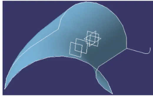
Transforming Geometry by Scaling
This task shows you how to transform geometry by means of a scaling operation. Open the Transform.CATPart document from the online/Samples/ShapeDesign directory.1. Click the Scaling icon . The Scaling Definition dialog box appears.
2. Select the Element to be transformed by scaling.
3. Select the scaling Reference point, plane or planar surface.
4. Specify the scaling Ratio by entering a value or using the drag manipulator.
The figure below illustrates the resulting scaled element when the plane is used as reference element (ratio = 2).
The figure below illustrates the resulting scaled element when the point is used as reference element (ratio = 2).
5. Click OK to create the scaled element.
The element (identified as Scaling.xxx) is added to the specification tree. The original element is unchanged.
Transforming Geometry by Affinity
This task shows you how to transform geometry by means of an affinityoperation.
Open the Transform.CATPart document from the online/Samples/ShapeDesign directory.
1. Click the Affinity icon .
The Affinity Definition dialog box appears.
2. Select the Element to be transformed by affinity.
3. Specify the characteristics of the Axis system to be used for the affinity operation:
the Origin the XY plane the X axis.
The figure below illustrates the resulting affinity with ratios X = 2, Y =1 and Z=1.
The figure below illustrates the resulting affinity with ratios X = 2, Y =2 and Z=1.
5. Click OK to create the affinity element.
The element (identified as Affinity.xxx) is added to the specification tree. The original element is unchanged.
Rotating Geometry
This task shows you how to rotate geometry about an axis.Open the Transform.CATPart document from the online/Samples/ShapeDesign directory.
1. Click the Rotate icon . The Rotate Definition dialog box appears.
2. Select the Element to be rotated. 3. Select a line as the rotation Axis. 4. Enter a value or use the drag manipulator to specify the rotation Angle.
5. Click OK to create the rotated element.
The element (identified as Rotate.xxx) is added to the specification tree. The original surface is unchanged.
Extrapolating Surfaces
This task shows you how to extrapolate a surface boundary .1. Click the Extrapolate icon .
The Extrapolate Definition dialog box appears.
2. Select a surface Boundary.
Select the surface to be Extrapolated. 3.
Specify the Limit of the extrapolation by either: 4.
entering the value of the extrapolation length selecting a limit surface or plane.
Specify Extremities conditions:
Tangent: the extrapolation sides are tangent to the edges adjacent to the surface boundary.
Normal: the extrapolation sides are normal to the orginal surface boundary.
5.
5. Select the Assemble result check box if you want the extrapolated surface to be assembled to the support surface.
6. Click OK to create the extrapolated surface.
Extrapolating Curves
This task shows you how to extrapolate a curve.1. Click the Extrapolate icon . The Extrapolate Definition dialog box appears.
2. Select a point or a curve.
3. Select the curve to be Extrapolated:
entering the value of the extrapolation length selecting a limit surface or plane.
4. Specify Continuity conditions:
Tangent: the extrapolation sides are tangent to the edges adjacent to the surface boundary.
5. Click OK to create the extrapolated curve.
Inverting the Orientation of Geometry
This task shows you how to easily invert the orientation of a surface or curve. 1. Select the Insert > Operations > Invert Orientation command.2. Select the surface or curve whose orientation is to be inverted. An arrow is displayed indicating the orientation of the element. 3. Click the arrow to invert the orientation of the element.
4. Click Invert Orientation again to accept the inverted element.
Creating the Nearest Entity of a Multiple
Element
This task shows you how to create the nearest entity of an element that is made up from several sub-elements.
1. Select the Insert > Operations > Near command. The Near Definition dialog box appears.
2. Select the element that is made up from several sub-elements.
3. Select a reference element whose position is close to the sub-element that you want to create. This example shows a parallel curve comprising
three sub-elements.
This example shows the sub-element that is nearest to the reference point.
4. Click OK to create the element.
Editing Surfaces and Wireframe
Geometry
CATIA - Generative Shape Design provides powerful tools for editing surfaces and wireframe geometry.
Editing Surface and Wireframe
Definitions
This task shows how to edit the definition of an already created geometric element.
1. Activate the Definition dialog box of the element that you want to edit in one of the following ways:
Select the element then choose the xxx.object -> Definition command from the contexual menu
Select the element then choose the Edit -> xxx.object -> Definition command
Double-click the element identifier in the specification tree.
2. Modify the definition of the element by selecting new reference elements or by entering new values.
Copying and Pasting
This task shows how to copy and paste open body entities in your part design.
1. Select the elements that you want to copy either directly in the part geometry or in the specification tree.
2. Select the Edit -> Copy command.
3. Click the Open Body entity in the tree where you want to paste the selected elements.
4. Select the Edit -> Paste command.
The elements are copied into the target Open Body.
The identifiers of copied elements are incremented with respect to the original elements.
Deleting Surfaces and Wireframe
Geometry
This task shows how to delete geometry from your design.
1. Select the entity you want to delete.
2. Select the Delete command either from the Edit menu or the contextual menu.
The Delete dialog box appears.
3. Set the desired options for managing the deletion of parent and children entities
Using Tools for Shape Design
CATIA - Generative Shape Design provides powerful tools to help you manage and analyse your surfaces and wireframe geometry.
Updating Your Design Using the Historical Graph Working with a Support
Creating Datums Creating Constraints Managing Groups
Performing a Draft Analysis Performing a Mapping Analysis
Checking Connections between Elements
Updating Your Design
This task explains how and when you should update your design.The point of updating your design is to make the application take your last operation into account. Indeed some changes to geometry or a constraint may require rebuilding the part. To warn you that an update is needed, CATIA
displays the update symbol next to the part name and displays the corresponding geometry in bright red.
1. To update the part, click the Update icon .
However, keep in mind that some operations such as confirming the creation of features (clicking OK) do not require you to use the update command. By default, the application automatically updates the operation.
Controlling your update is possible: just select the Tools -> Options
command and uncheck the automatic update option to make sure you will update your part only when you wish to do so.
2. To update the feature of your choice, just select that feature and use the Update contextual command.
Using the Historical Graph
This task shows how to use the Historical Graph.1. Select the element for which you want to display the historical graph. 2. Click the Show Graph icon . The Historical Graph dialog box appears.
The following icon commands are available. Add graph
Remove graph Reframe graph
Surface or Part graph representation Parameters filter
Constraints filter.
Working with a Support
This task shows how to work on a support, which may be either a plane or a surface.
This will allow you to easily reference a surface or plane whenever you need one. For example, you will not have to explicitly select the support element again when creating geometry.
1. Click the Work on Support icon .
The Work on Support dialog box appears.
2. Select the plane or surface to be used as support element. If a plane is selected, a grid is displayed to facilitate visualization.
When you no longer need the support, just click on the icon again then click the Remove Support button.
Creating Datums
This task shows how to create geometry with the History mode deactivated. In this case, when you create an element, there are no links to the other entities that were used to create that element.
1. Click the Create Datum icon to deactivate the History mode. It will remain deactivated until you click on the icon again.
If you double-click this icon, the Datum mode is permanent. You only have to click again the icon to disactivate the mode.
A click on the icon activates the Datum mode for the current or the next command.
The History mode (active or inactive) will remain fixed from one session to another: it is in fact a setting.
Creating Constraints
This task shows how to set geometric constraints on geometric elements.
Such a constraint forces a limitation. For example, a geometric constraint might require that two lines be parallel.
To set a constraint between elements: 1. Multi-select two or three elements to be constrained. 2. Click the Constraint with dialog box icon
. The Constraint Definition dialog box appears indicating the types of constraint you can set
between the selected elements. 3. Select one of the available options to specify that the corresponding constraint is to be made. 4. Click OK. The corresponding constraint symbol appears on the geometry.
To set a constraint on a single element: 1. Select the element to be constrained. 2. Click the Constraint icon . The corresponding constraint symbol appears on the geometry.
Managing Groups
This task shows how to manage groups of elements in an Open Body entity as follows:
creating a group editing a group
collapsing and expanding a group moving a group to a new body.
Creating a group
1. Right-click the desired Open Body entity in the specification tree. 2. Choose the Create Group command from the contextual menu.
The Group dialog box appears.
The Support area indicates the name of the Open Body entity where the group is to be created.
3. If needed, modify the proposed default group name that appears in the Name area.
4. Select entities to be included in the group and remain visible in the tree. 5. Click OK