Software Project Support Tool
P3 Project
Group s301a
Department of Computer Science
Aalborg University
18th of December 2008
Aalborg University
Department of Computer Science
Selma Lagerløfs Vej 300 Telefon +45 9940 9940 Fax +45 9940 9798 http://cs.aau.dk
Title: Software Project Support Tool Theme: Programming in the large
Project period:
SW3, Autumn semester 2008 Project group:
s301a Participants:
Kasper Gadensgaard Nielsen
Aso Mahmood Zada
Simon Stubben
Jesper Kjeldgaard
Supervisor:
Darius Sidlauskas Copies of report: X Report page count: 80 Appendices: X
Report finished: 18. December 2008
Synopsis:
This project concerns developing a soft-ware project support tool. The develop-ment process is clarified in four chapters, namely analysis, design, implementation and testing.
The analysis regards what is required by the application, by, among other things, looking at existing systems and which soft-ware qualities are expected to be focused on when developing the tool.
The design chapter describes the alterna-tives and consequences of designing the ap-plication, among these are OOP as pro-gramming paradigm, multi tier architec-ture as software strucarchitec-ture and the choice of MSSQL as data source.
The implementation chapter completes the development process by showing how the application was implemented using the methodologies applied.
The second to last chapter in the report, testing, outline how testing of the software product was performed.
To finish the report the last chapter evalu-ates, reflects and concludes on the project and the appurtenant application.
The content of this report is publicly available, publication with source reference is only allowed with authors permission.
Preface
This report is the result of Software Engineering group S301A’s 3rd semester project at the Department of Computer Science, Aalborg University. The re-port is documentation for the project, proceeding in the period from 2nd of September till 19th of December, 2008. The goal of the project was to gain knowledge of programming in the large through developing a software project support tool.
Throughout the report, cites and references to sources will be denoted by square brackets containing a number corresponding to an entry in the bibliog-raphy. Abbreviations will be expanded the first time it appears in the report.
When a person is mentioned ashethroughout the report, it refers tohe/she.
The reader is expected to have basic knowledge of computers and program-ming.
The report is build up in five chapters:
• Analysis
The analysis chapter covers the basic analysis of project management in general, existing project management systems and defines the requirement specification and quality goals for the product of this project.
• Design
The design chapter derives from the analysis chapter, and covers the struc-turing and design of the software product.
• Implementation
The implementation chapter covers the actual programming of the soft-ware product based on the design phase of the development process.
• Test
The test chapter contains systematic testing of the software product, in-cluding user testing, unit testing and test driven development.
• Recapitulation
The recapitulation chapter contains a discussion of the result of the soft-ware project, and concludes on the problem stated in the analysis chapter. In addition, it contains a reflection about the project process, and how the project could have evolved if more time was available.
Software Project Support Tool
Appendices can be found in the end of the report. The source code for the software product and online references is included on the attached CD-ROM.
Approach
To ensure that a project respects its deadline it is important to plan the ac-tivities to be carried out. To give the reader some knowledge of the basis of this project, the following will describe the process of developing the supplied product using agile development methods.
Choice Of Development Method
There are many different development methods for solving a given problem in a software project. A development method is a tool for the development team, containing a way to plan, implement and keep the project on track.
From the start of the project we all agreed, that using an agile development method would be a suitable choice, for implementing the product of this project. Some group members have had good experiences with it from earlier projects, others have never used it but found it appealing in the nature of this project.
One alternative was the waterfall method, which requires the project mem-bers to gain lots of knowledge on the subject and do a lot of planning of the process before starting the actual implementation, whereas the agile develop-ment methods encourage thelearning by doingapproach. The waterfall method is well known by all members, however, since all of the group members had none or limited experience in developing a website of the scale of this project, or in developing in ASP.NET and C#, we chose an the agile approach, mainly to get some hands-on experience.
There are several methodologies under agile software development, but they all have in common that they are iterative, which means that the development process consists of consecutive increments, each adding more functionality to the software product [5]. The agile development methods are based on twelve principles, listed in appendix D [7]. These principles are meant as overall guide-lines and each principle should be individually considered for any given agile software development project.
The practices of Scrum and Extreme Programming (XP), two of the most widely used methodologies under agile software development, elaborated in sec-tion 2.1, allowed us to start coding right away and hereby get some hands-on experience and an idea of approximately how demanding this project would be. This experience enabled us to make a better estimate on how long it would take to go through each iteration, which then resulted in a more realistic time schedule. Moreover, we found the practices Planning Game, Collective Code
Software Project Support Tool
Ownership, Pair Programming, Refactoring and Short Iteration Cycles very appealing to this project, elaborated in section 2.1.
To sum up we chose the agile development approach for the following rea-sons:
• Personal experiences and expectations
• Hands-on experience
• Pair programming
• Small Releases
Milestones
After each iteration, we released a working copy of the software, and planned the next iteration of the development process. Furthermore, to get a general and broad perspective of the process, we established a set of overall milestones containing a collection of iterations expected to be finished at a certain deadline. These milestones functioned as an internal time schedule to keep track of the project status.
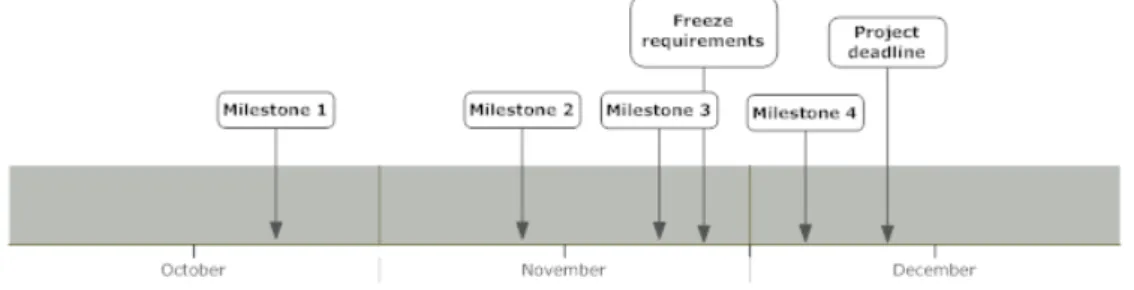
The figure below shows a timeline, containing the set of milestones estab-lished for this project. The details and contents of each milestone is described in appendix A.
Figure 1: Project Milestones
Planning these milestones, we had to take into account that a lot of courses were scheduled in the first two months of the semester, hence the workload for the project in this period of time should be less. Moreover, the milestones should contain some planned buffers, enabling us to catch up on possible overdue project activities. By planning these buffers, we prevented possible problems to cause delay in the development process.
Software Project Support Tool
By using these milestones as minor goals, we were able to keep track of the overall project status, and hereby adjust the workload to keep up with our deadlines.
Burn-Down Chart
To give a visual overview of the project status, we created a burn-down chart to represent the number of activities still remaining in our project. The burn-down chart is represented as a graph, plotting the number of unfinished activities remaining every week of the project period. As the project progresses the graph should show a declining curve and preferably hit the x-axis before the project deadline. To stay updated we drew the burn-down chart on the blackboard in our group room and revised it each week.
Contents
Preface . . . 1 Approach . . . 3 1 Introduction 9 2 Analysis 11 2.1 Project Management . . . 112.2 Existing Project Management Systems . . . 14
2.3 Requirements Specification . . . 18
2.4 Development Platform And Framework . . . 21
2.5 Software Quality Goals . . . 24
2.6 Thesis Statement . . . 28 3 Design 31 3.1 Programming Paradigm . . . 31 3.2 System Architecture . . . 33 3.3 Website Structure . . . 36 3.4 Data Source . . . 38 3.5 Quality Assurance . . . 42 3.6 Summary . . . 44 4 Implementation 45 4.1 Design Patterns . . . 45 4.2 Classes . . . 47 4.3 Handlers . . . 48 4.4 RDBMS . . . 49 4.5 Stored Procedures . . . 50 4.6 User Interface . . . 51 4.7 Code-Behind Files . . . 54
Software Project Support Tool CONTENTS 4.9 Summary . . . 57 5 Test 59 5.1 Introduction . . . 59 5.2 User Testing . . . 59 5.3 Unit Testing . . . 59 5.4 TDD . . . 61
5.5 Bug Tracking And Fixing . . . 62
5.6 Summary . . . 62
6 Recapitulation 63 6.1 Evaluation And Future Perspectives . . . 63
6.2 Reflection . . . 65
6.3 Conclusion . . . 66
Appendices 70 A Project planning 71 A.1 Milestones . . . 71
A.2 Burn-down chart . . . 72
B Flowchart 73
C Database Diagram 75
D Agile Manifesto 77
Chapter 1
Introduction
This project deals with the making of a software project support tool. The report covers the process of implementing the tool using suitable technologies and methodologies. Our experience and problems with project management is the motivation for creating this project.
Through the last decades of software development, project management has become a more integrated part of the development process. The broad work with projects has resulted in a lot of knowledge about managing a project in many different settings and situations.
Today a majority of software developing companies make use of project management in the development process. This has lead to a market for software project support tools. One of the most commonly used in the business industry is Microsoft Project, which is a commercial professional project management tool with an extensive set of features. These tools are able to help the project manager by making it easier to schedule the resources available and the overall progress.
When developing a software project support tool it is important to con-sider several factors. For example, what makes a tool able to measure progress and how does the tool deal with several projects, resources and activities? In the analysis chapter, the pros and cons of some existing project management systems will be elaborated, a set of quality goals will be stated and a require-ment specification for our software project support tool is derived. From these requirements our tool is designed and implemented.
Initial Problem
Software Project Support Tool
How can a piece of software help a software project to succeed?
Through the following chapters, our decisions for the development process are taken into account and the alternatives and consequences of the choices are considered.
Chapter 2
Analysis
A software project support tool can be developed in many different ways. The following chapter includes a quick description of project management in gen-eral and a brief analysis of already existing software project support tools. Subsequently, the requirements and quality goals for our product is presented. Finally, the thesis statement concludes the chapter.
2.1
Project Management
For writing a software project support tool an elaboration of a project and project management in general is reasonable, as these lead to the core of the product and this report. Therefore, in this section, a definition of a project and a brief explanation of project management is stated. A project is defined as:
An extensive task purposely and collectively undertaken by a group or indi-viduals to apply knowledge and skills toward a targeted goal which will result in a product, within a certain time frame.[8]
A project is often taken care of in teams, as it, among other things, enables the possibility to distribute the work among team members and involve external specialists. Thus, as it is a greater task with one primary objective, namely to complete a specific project goal, and with several individuals included one might find it profitable to use some kind of planning method to overcome the project; hence, project management is defined:
Project management is a carefully planned and organized effort to accom-plish a specific (and usually) one-time effort, for example, construct a building or implement a new computer system.[3]
Project management includes developing a project plan, for example spec-ifying activities, resources available, deadlines and the overall budget of the
Software Project Support Tool 2.1. Project Management
project. A project plan can give an overview of the project’s current status, which is important for maintaining the leitmotif and project deadline.
The use of project management systems is seen more and more in the labor market as a working method, especially in software development, to assist the process of problem solving, for example creating a new product or application. The companies use it, as they have found out that project management eases the process and often results in a better product. However, this is not always the case.
Research has been made by surveyors to identify why some projects fail. IT Cortex, an IT consulting company, has looked at the different surveys conducted and from these it is concluded that many of the project failures are caused by a lack of communication between relevant parties, for example group members, client and supplier, as a result of poor project management [2].
These surveys were made in the late 90’s and project companies have learned from this. Nevertheless, the causes are still to be taken seriously. To ease the process of project management, software support tools were created and found their way to the counter both as proprietary products and open source software. A brief analysis at some of the existing support tools is provided in section (2.2).
Project management generally has a couple of major phases to overcome. These phases may vary due to the nature of the project, but the following points out the typical for software projects:
• Analysis
• Design
• Implementation
• Evaluation and test
• Maintenance and support
These phases each define an important step in the development process. Through the process an analysis of the problem, a design and implementation of the solution, and systematic testing and evaluation to verify the solution, is needed. After the release, the customers may have modifications or further problems to be solved. For most projects the maintenance phase is the most time consuming phase, since it often spans a longer period of time. Although these phases are general for most software projects, not all projects are the same, for example due to different activities, resources and the subject of the projects; consequently, different project management methodologies have been
Software Project Support Tool 2.1. Project Management
developed. As mentioned in the approach section, agile development is used as method for this project. The next couple of paragraphs will briefly describe agile development and elaborate on the two most popular and widely used methodologies, Scrum and XP.
Agile Development
An agile process can be described very shortly as a process consisting of short iterations of work that deliver small increments to the project. By the end of each iteration, the system should be stable and usable. Agile software devel-opment parents many methodologies; each includes different sets of guidelines and practices to be used in the development process.
Scrum is an agile development method, which features short processes of 30 days typically. These short processes go by the namesprints. During a sprint the requirements are frozen and a pre-release is made, that is the project team develops a usable piece of software without changing the requirements until next sprint. An important element in Scrum is the short daily meetings, which ensures knowledge sharing and communication between the project members [18].
XP is based on five values, namely: simplicity, communication, feedback, courage and respect. These values ensure that simple code is produced, and that communication and feedback among all parties concerning the project process is maintained. [1]
These two methods each define a set of practices to be used in the software development process. Some of the practices, used in this project are elaborated in the following.
Planning Game is a practice from XP, which plans the process of the project. The planning game consist of a meeting to be held once per iteration to ensure release planning reaches the expected aim. The release planning involves cre-ating user stories from the requirements of the given increment and to create a plan for next release iteration cycle. This plan defines which overall require-ments to include/edit/exclude for the present iteration. Some of the benefits of using the planning game are the ability to keep a sense of perspective of the project progress and to edit the requirements continuously.
Pair Programming is another practice of XP. Pair programming is program-ming done by two developers at one computer; one implementing program code and the other thinking about structure and discovering possible problems and errors. By practicing pair programming the developers’ programming skills are
Software Project Support Tool 2.2. Existing Project Management Systems
improved, as it enhances the knowledge sharing. Moreover, by being two devel-opers, ideally pair programming will produce better code. Pair programming makes distributing work amongst group members easier, which is important for the common understanding, in between the group members.
Collective Code Ownership is an additional practice of XP. This allows everybody working on the project to change all parts of the code. Pair pro-gramming and the use of a version control system contributes to this practice, by letting everybody know what is going on in the project. Moreover, if a pro-grammer is absent another propro-grammer can take over, without any delay of the development process.
Refactoring is a general practice included in most agile development meth-ods. Refactoring is changing the code without changing the end results. Refac-toring is not bug fixing, but is mainly focused on cleaning up the code, making it easier to understand and maintain and improving the performance of the application.
Short Iteration Cycles is also a general practice of agile development. By releasing stable software in short iteration cycles, it is easier to keep track of the project status. Moreover, the customer is able to keep abreast of the development process of the software.
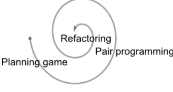
These practices are just a few of many different practices defined in the two methods. Figure 2.1 illustrates a short iteration cycle using the practices mentioned above.
Figure 2.1: Short Iteration Cycle
2.2
Existing Project Management Systems
Today, a lot of project management tools are available. They vary from web based solutions to desktop applications and are licensed under both open source and proprietary licenses. We have chosen to take a closer look at four of these
Software Project Support Tool 2.2. Existing Project Management Systems
existing project management systems. This is done to get a better idea of what other developers did to solve some of the same problems as those we are facing in this project. The tools we will be analyzing are Gantt Project, eGroupWare, Trac and Microsoft Project. This section will do a brief analysis on these tools, and describe the pros and cons using them.
2.2.1 Gantt Project
Gantt Project is a desktop application aimed at project scheduling, and there-fore it is not a complete project management system. The two main features of the tool are Gantt charts and resource load charts. A Gantt chart shows the different tasks and phases scheduled in a calendar view. Figure 2.2 is an example of a Gantt chart that shows the schedule and progress of a sample project [17].
Figure 2.2: Gantt Project example
Gantt Project uses Gantt charts as both a planning tool and a progress monitor by showing the task completion percentage as black lines inside the schedule. This feature enables the user to get a better overview of the project. The resource management feature allows the project manager to assign human resources to project activities, hereby helping him schedule and optimize work hours for the project. While being a great tool for general project management, Gantt Project has some shortcomings when used in a software project. The most obvious flaw is that the application is aimed at only being used by the project manager and therefore does not allow developers to update their own tasks, and keep track of the project status. Another flaw is when working with
Software Project Support Tool 2.2. Existing Project Management Systems
projects that contain large numbers of tasks, having all tasks in one screen can get confusing.
2.2.2 eGroupWare
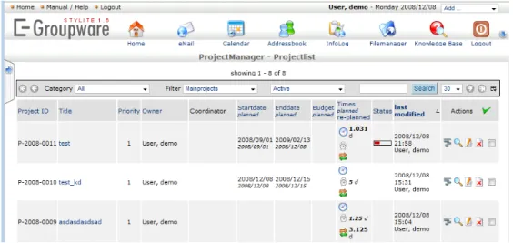
eGroupWare is an open source web based management system, which main purpose is to help businesses managers administer information for example about projects, contacts and employees. The primary functionalities of the tool are contacts management, calendar and web mail. Beyond these functions eGroupWare can be extended with other applications such as a project manager, resource manager and a wiki. With all these applications eGroupWare becomes a very complex tool that could easily support big enterprises since it covers almost all aspects of costumer, project and employee management. Due to the complexity of this tool it has a steep learning curve and might be a bit over the top for smaller projects.
Figure 2.3: eGroupWare example
One of the biggest pros of using eGroupWare is the web based adminis-tration system, allowing all project members to access and modify the tool at the same time. This feature would be very useful in a software project with several developers working at the same time. Another very useful feature is the calendar, allowing the project members to synchronize their work schedule.
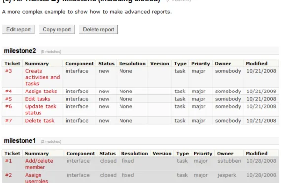
2.2.3 Trac
Trac is an open source web based tool for managing tasks and bugs in a software project. The main features include a web interface to a version control system, bug database, road map, time line and wiki. The built-in web interface for version control enables the users to browse the source code and in an intuitive manner get information about changes.
Software Project Support Tool 2.2. Existing Project Management Systems
Figure 2.4: Trac Screendump
Bugs and tasks are represented as tickets with several attributes like priority, assigned to, version, attachments and change history. It is up to the developers to close their own tickets if the issue is resolved or the task is complete. The tickets are grouped by release version or the milestone to which they belong. The time line shows a detailed list of changes. The road map feature enables the users to view progress bars on each milestone or release. These progress bars are based on the number of closed tickets out of the total amount of tickets for that milestone or release.
Trac sums up to be quite a useful tool when developing software, and also covers future maintenance of the project. A major pro of using Trac is the simple progress bar that enables a quick overview of the project status. Another pro is the intuitive ticket based system, which makes it easy to manage tasks and bugs.
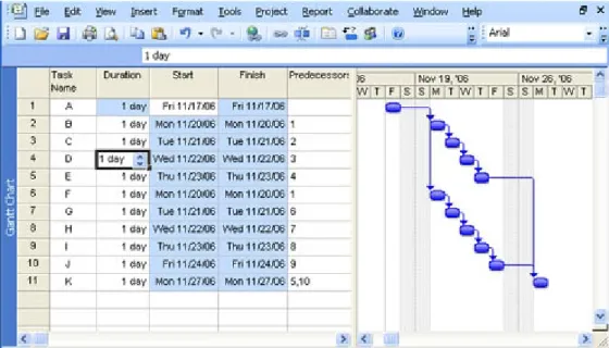
2.2.4 Microsoft Project
Microsoft Project is one of the biggest and most popular project management tools available. It includes all sorts of features like resource management, progress charts, work distribution, task scheduling, integration with other Mi-crosoft products and much more. All these features sum up in a great tool for
Software Project Support Tool 2.3. Requirements Specification
Figure 2.5: Microsoft Project Screendump
managing projects of unlimited size and proportions. However, while being a general project management tool it lacks some features that are useful when managing software projects, for instance the possibility for multiple users to update and manage their task status simultaneously. This is due to Microsoft Project aiming at project managers and not project members.
To sum up this section, the following list shows what features and ideas we have found to be good to include in our project management support tool.
• Resource management, allows us to assign project members to activities, and keep track of project resources.
• The ability to login to the site and have multiple users online at the same time, managing and maintaining the project activities.
• A ticket system to manage activities for the project.
• Graphs and charts to give an overview of the project velocity.
These items will be taken into consideration when choosing the features for our project management system.
2.3
Requirements Specification
For any given project there are specific requirements from the costumer and stakeholders that need to be respected. In our case these requirements are
Software Project Support Tool 2.3. Requirements Specification
derived from our ideas of a software project support tool and what is imposed from the obligatory requirements for the project of this semester. In addition, after reviewing some existing systems, we have gained additional ideas of which functionalities should be included as well. This requirement specification is following the IEEE STD 830-1998 standard. This standard basically consists of five areas, each of which is covered in the following section.
2.3.1 Functionality
The software system should allow registered users to manage projects and tasks according to their role in the given project. These functionalities are elaborated later in this section.
Login System And User Data
To increase security and keep track of users, the system should contain func-tionality that allows users to register and login to the web application. This registration should include a profile with full name, semester, group and qualifi-cations. Furthermore the system should keep track of which projects each user is a member of, which tasks each member is assigned to and the role of each member in a given project.
User Roles
To restrict access to functionality the system should be able to manage different user roles. There are four different user roles, each defining which functionalities the users have access to. The following describe the supported roles of each project member. The structure of the roles are hierarchical, meaning that permission policies are passed on to roles further up in the hierarchy. For instance, the manager has further permissions than the developer, but is allowed to do everything the developer is allowed to do. The different roles are, ordered from highest to lowest permission level, given below:
1. Manager 2. Developer 3. Supervisor 4. Spectator
The manager should have access to all pages and should be able to execute all functionality on the project he is assigned to. This is the only role that should be able to edit/delete a project and add/edit/delete members. The developer can edit all tasks inside a project, including assigning users to tasks. The supervisor should be able to view and comment on all tasks and members in
Software Project Support Tool 2.3. Requirements Specification
a project, but not edit anything. The spectator role, the lowest in the hierarchy, should have access only to the project dashboard.
Projects
To make the support tool more flexible, we have required the possibility for managing multiple projects. Each project added to the support tool should include information about project name, description, current status, deadline and, if it is mentored, which supervisor mentoring the project. This element is vital for a software project support tool.
Tasks
By dividing the project into tasks, and keep track of each task status, it is possible to keep the members updated about the project status. Thus, task management is a requirement to the support tool. A task is defined by: A name, description, deadline, status, progress and to which project member it is assigned. Members should only be assigned to tasks if they have the qual-ifications required to complete the task. Furthermore the tasks should have estimated work hours.
Comments
It should be possible to comment on tasks, bugs and projects. This would enhance communication amongst the project members.
Bugs
The system should include a feature that allow users to report bugs in a project. Bugs should contain the following properties: A title, description, status, to whom it is assigned, who reported it, type and priority.
Overall Schedule And Project Monitoring
It should be possible to schedule and monitor the status of each project by generating graphs based on live data, for example a burn down chart repre-senting tasks remaining. Beside graphs the site should supply the users with an overview of all the tasks being worked on and if they are respecting their deadline. The task status should be signaled by traffic lighting colors, repre-senting tasks completed, in progress or overdue and so on. Furthermore the users should be able to keep track of the task they are assigned to for each project.
Software Project Support Tool 2.4. Development Platform And Framework
Live Data
The system is required to work with live data from the project, for example data retrieved from a database, edited in the system and subsequently stored the database. The system should include itself as a project when the basic functionality is implemented, that is the development of this project should be managed using the software project support tool.
2.3.2 External Interfaces
The system should be accessible through a web browser. This makes the system available to all users with an Internet connection, hereby reaching the maximum availability for any software system.
2.3.3 Performance
The system is expected to be quite fast since there are no requirements for a high end graphical user interface. This greatly reduces the amount of In-ternet bandwidth used, however no further considerations towards enhancing performance is taken.
2.3.4 Design Constraints Imposed On implementation
The main course of this semester is object oriented programming (OOP), hence our system is going to be implemented using this paradigm. The OOP course covered the C# programming language, therefore this system will be imple-mented using it.
2.4
Development Platform And Framework
For building software applications it enhances the productivity if a flexible and intuitive development environment and programming language are used. This section will cover our choice of development platform and programming language.
2.4.1 Framework
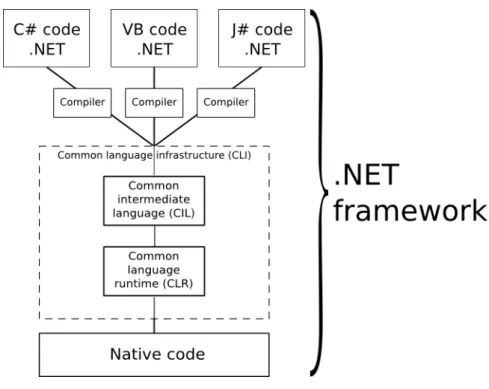
As framework for our software product we have chosen the Microsoft .NET framework, because of its many tools and the well defined documentation. In general, the .NET framework helps the developer, by giving a set of tools for programming and execution, when he is coding in a supported language i.e. C# or VB.
The .NET framework basically consists of two parts; a standard class li-brary with preprogrammed solutions and a virtual machine to handle the
ex-Software Project Support Tool 2.4. Development Platform And Framework
ecution. The standard library has solutions for many common problems, such as reading and writing to files, graphic rendering, database interaction and so on. Additionally more advanced functionality like member handling and role management is included in the standard libraries. All this functionality in the .NET framework is available through the supported languages. Each supported language has its own compiler which generates the same type of byte code, to be executed by the interpreter; the virtual machine. A graphic representation of the .NET framework is illustrated in figure 2.6
Figure 2.6: The .NET Framework
A program written in the .NET framework is able to compile and execute on any system or platform with the .NET framework installed [13].
2.4.2 Programming language
As programming language for this software project, we chose C# and Active Server Pages (ASP), mainly because we followed the course of OOP, but also because they both are supported by the .NET framework, which, as mentioned above, gives a lot of built in features and design advantages.
C# is a general purpose Object Oriented Programming (OOP) language developed by Microsoft and released in 2001, hence a very young and modern programming language. Since it was developed in the late 90’s, Microsoft had a chance to look at the already developed and stable languages and to learn from these to make C# even better. Thus, C# is deeply influenced by Delphi,
Software Project Support Tool 2.4. Development Platform And Framework
Java and of course its ancestor C++. A brief evaluation of C# points out pros and cons in the following. [16]
Pros
• Fast learning curve; mainly because of the included libraries and the syn-tax is very similar to Java and C++.
• Many potential uses; one can use it locally for a console application or as a code-behind language in ASP.NET web application.
• The compiler is installed with the Microsoft .NET framework, which eases the use on Microsoft Windows.
Cons
• Can be slow; as C# is based on the .NET framework, it runs in a virtual machine, which can be slow at runtime.
• More or less platform dependent; C# is very much bound to Windows even though .NET implementations is made for other platforms, i.e. MONO for Linux/UNIX.
As mentioned, ASP.NET is used as well. ASP.NET contains a set of de-velopment tools which also is developed and published by Microsoft. By using ASP.NET, programmers are able to develop for example dynamic web pages, web applications or web services. ASP.NET is part of the .NET framework and therefore uses the same virtual machine, which allows programmers to use ASP.NET in combination with all the supported .NET framework programming languages [12].
For developing a web tool or more specifically a web based software project support tool for this project’s case, C# in combination with ASP.NET seems as a sensible choice.
2.4.3 Development Environment
Our software product is primarily programmed using Visual Studio. Visual Studio is an Integrated Development Environment (IDE) for Microsoft Windows developed and published by Microsoft. This development tool offers support for a wide variety of programming languages of the .NET framework, such as C# and ASP.NET.
Visual Studio is a professional IDE with a lot of complicated features, how-ever it is also a useful for novice users as it features a wide range of built in, easy to use, drag and drop tools for building advanced applications. Visual Studio
Software Project Support Tool 2.5. Software Quality Goals
is a powerful tool for designing and programming form applications, console applications, web applications, web services and much more.
Visual Studios code editor includes Intellisense, providing the developer a convenient way of accessing descriptions of methods, providing a list of input parameters, and a description of the methods return value. IntelliSense speeds up the development process by reducing the amount memorization and key-board input required. Also built in hotkeys provides the developer with one key access to documentation of the standard libraries. In addition, Visual Stu-dios build in WYSIWYG graphical designer allows the developer to drag and drop controllers and design elements directly into the application. [14]
To sum up, Visual Studio provides a lot of useful tools for developing a software application, allowing the developer to design, program, debug and run software applications directly from the development environment [15].
2.5
Software Quality Goals
When developing a software product or service, a project group may expect some certain functions or design features to be fulfilled; that is, an assured soft-ware quality is expected. Hence, defining quality goals for any softsoft-ware system is an important step in the early stages of the system analysis. From these quality goals, the best fitting approach for the system design and development will be derived.
In this section, the most commonly agreed software quality factors are pre-sented, and it is pointed out which factors are highly prioritized in this software project support tool.
2.5.1 Quality Factor Definition
In every software development project, the specified quality goals vary upon the nature of the software system. Thus, a lot of different factors are to be considered when the quality goals of a specific software system is contemplated. Most of these factors can be derived from the eleven most commonly agreed on quality factors, listed in table 2.1. These factors should be individually considered in the specification of any software system’s quality goals.
2.5.2 Software Quality Trade-Offs
When deciding quality factors for any software system, some quality factor trade-offs should be considered. That is, the existence of criteria character-istics belonging to any given quality factor could have impact on the degree of implementation of some other quality factors, as shown in figure 2.7. That
Software Project Support Tool 2.5. Software Quality Goals
Quality Factor Definition
Correctness Extent to which a program satisfies its specifications and fulfills the user’s mission objectives.
Reliability Extent to which a program can be expected to perform its intended function with required precision.
Efficiency The amount of computing resources and code required by a program to perform a function.
Integrity Extent to which access to software or data by unautho-rized persons can be controlled.
Usability Effort required to learn, operate, prepare input, and interpret output of a program.
Maintainability Effort required to locate and fix an error in an opera-tional program.
Testability Effort required to test a program to ensure it performs its intended function.
Flexibility Effort required to modify and operational program. Portability Effort required to transfer a program from one hardware
configuration and/or environment to another.
Reusability Extent to which a program can be used in other applica-tions related to the packaging and scope of the funcapplica-tions that the program performs.
Interoperability Effort required to couple one system with another. Table 2.1: Quality Factor Definitions [20].
Software Project Support Tool 2.5. Software Quality Goals
is, applying a high degree of one factor may compromise the degree of other quality factors.
In case of a negative impact between factors, the importance of the trade-off should be considered by the software development team. If, for example, human lives depend on the reliability of the software system, this quality factor should be emphasized over reusability.
Figure 2.7: Quality trade-offs between software quality factors [20].
2.5.3 The Quality Goals of this project
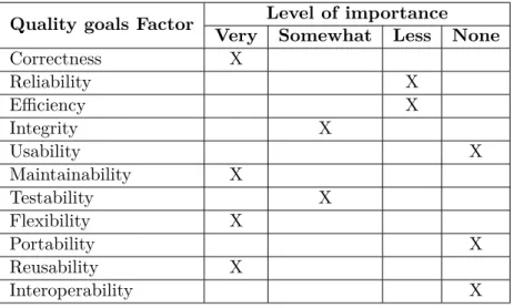
In the nature of this software project where different groups work with the same topic, a lot of different approaches could be made, depending on the focus from each project group. Table 2.2 shows the quality factors in focus for our software project support tool.
As appears from table 2.2, the main focus in this project is correctness, maintainability, flexibility and reusability.
In the following, the choices of quality goals to be focused on for this project is accounted for.
Software Project Support Tool 2.5. Software Quality Goals
Quality goals Factor Level of importance Very Somewhat Less None
Correctness X Reliability X Efficiency X Integrity X Usability X Maintainability X Testability X Flexibility X Portability X Reusability X Interoperability X
Table 2.2: The Quality Goals of our project
Correctness
Any software system should meet the expectations and specified requirements. The requirements for this project are well defined, and our system should strive to fulfill these requirements. The software system is at no use if it does not perform as intended, thus our system should function as specified in the re-quirement specification.
Maintainability
Integrating a high level of flexibility requires a high level of maintainability. Moreover the system should be easy to maintain, errors should be easy to fix and so on thus a high degree of maintainability is required for our system. Once the system is running, maintenance would be regarding fixing possible bugs and extending the system.
Flexibility
The potential of this software system, as a software project support tool is enor-mous and the amount of possible enhancing features is limitless. Accordingly the software system should be highly flexible, thus simply extensible.
Reusability
Reusability refers to design features of a software element that enhance its suitability for reuse. Implementing a high level of reusability is a high priority for this project.
Software Project Support Tool 2.6. Thesis Statement
Integrity
Integrity is only important for our system to some extent. The system is deal-ing with sensitive information, i.e. user passwords, and based on the user’s permission level for any given project, parts of the system functionality should be limited. Thus, our software system should deal with these security issues; however, this is not our main focus.
Testability
In order to assure that the desired level of correctness is achieved, some level of testability is required. However, testing of our system is not the main focus for this project, as elaborated in the chapter 5.
The quality goals reliability, efficiency, usability, portability and interop-erability are not a high priority for this project. Our main focus will be on implementing a functional software project support tool, and considerations about the less important goals is beyond the limits for this project.
2.6
Thesis Statement
Throughout this chapter we have analyzed how the use of project management support tools could help a software project to succeed and what features such a system should contain. We started by studying agile development methods and learned how they could assist us during the development of the software project support tool. This resulted in a selection of practices we thought to be useful and rewarding to use in the process of this project. Subsequently we analyzed the .NET framework and C# language, even though these were imposed on the project, to get some understanding of the basics on the development platform to be used.
A brief analysis of some of the existing project management systems helped us define the requirement specification for the support tool. These requirements function as the blueprint for our system. Furthermore, we advanced some software quality goals to assure the quality of the system. The quality goals are also meant to characterize what areas we wish to focus on during development.
Based on the problem analysis, a thesis statement can be derived, in order to narrow down the scale of this project:
How is a software project support tool developed from the given set of requirements and quality goals?
Software Project Support Tool 2.6. Thesis Statement
Considering this thesis statement, the following chapters will deal with the software technical issues of developing a software project support tool.
2.6.1 Problem Delimitation
Given the time restraint on this project we know that implementing a full scale software project support tool, with all the functionality we would like it to contain, is not possible. By full scale we mean carrying out agile development and test driven development to their fullest and gain all the benefits of these. Instead we will focus on learning and get some experience from the applied technologies, whilst still creating a support tool with basic functionality that achieves the quality goals and requirements stated in this chapter.
Chapter 3
Design
When creating a software application, the process always contains some amount of designing. In traditional development all designing takes place in the early stages of the process whereas agile development has divided the process out on separate iterations. Separating the design phase into smaller parts helps to ensure that changes late in a project does not render too much work forfeit but only the designing that has already taken place may be obsolete. Having adhered to several agile principles and practices in this project, the design of our software project tool has been an ongoing process throughout the imple-mentation of it. Therefore, at every new iteration, we had to think about how to design the certain feature.
In this chapter our choice of programming paradigm is described. Further-more, the design of the software project support tool is elaborated, including the decisions and thoughts we made during the development of the software product covered.
3.1
Programming Paradigm
Choosing the right programming paradigm is essential for any software project. Two of the most commonly used programming paradigms are imperative and OOP. One of the objectives of this project is using OOP as programming paradigm. This section, based on [6], gives a description of OOP, including classes, objects, inheritance and polymorphism. Additionally it is elaborated why OOP has been chosen as the programming paradigm for this software project.
To develop a software product using OOP means to divide the program into isolated parts reflecting real life objects. It gives the opportunity to give structure and design to the program even before the actual implementation
Software Project Support Tool 3.1. Programming Paradigm
is initiated. A reasonable design will result in an application that is easier maintainable at a later state.
The general idea of OOP is to take real life objects and describe them in a programming language as classes. These classes contain associated data or characteristics of the given element. The code class functions as a blueprint for creating objects. The object is an individual instance of a class and has particular features and properties derived from the class characteristics. Figure 3.1 gives an example of an object instantiated from a class.
Figure 3.1: Object instantiated from a class
In OOP the program code is separated into several individual classes with separate functionalities. This is opposed to imperative programming where the program is done step by step calling different subroutines. A good object oriented design allows examination of the relevant details of the program, where each object has specific roles and responsibilities, making the code is easier understandable.
OOP contains a set of fundamental concepts, describing a set of standards to be used in the programming paradigm. Two of these are inheritance and polymorphism.
3.1.1 Inheritance
A code class is able to inherit data and functionality from a class. To make the code even more reusable, inheritance can be used to create new classes from existing classes by absorbing their attributes and behaviors. That is, when building new class, it is possible to inherit the properties and functions from the the base class, instead of programming another similar class. The new class is referred to as a derived class. Each derived class itself becomes a candidate of being a base class for some future derived class.
3.1.2 Polymorphism
The main practice of polymorphism in OOP is the ability of objects, belonging to different types, to respond to a method or property call of the same name,
Software Project Support Tool 3.2. System Architecture
each one according to an appropriate type specific behavior. Thus, polymor-phism allows you to assign the same name to operations on different objects. The desired operation is selected dynamically, depending on the type of object in use. Polymorphism enables the developer to write programs in a general fashion to handle a wide variety of related classes.
Figure 3.2: Inheritance and polymorphism example
In figure 3.2 an example use of inheritance and polymorphism is illustrated. TheChartclass is the base class of bothBurnDownChartandStatusBarderived from this base class, and thereby inheriting the characteristics. Calling the DrawGraph()method on either will produce different charts depending on the specific type of the chart object.
3.2
System Architecture
Choosing the best fitting overall system architecture for any software system derives from the set of quality goals specified in the early stages of the software development process.
In this section it is pointed out why a suitable software architecture is bene-ficial in software development and how our software system is to be structured.
3.2.1 Multi Tier Architecture
Many software applications are intended to collect data from some data source and present it to the user. With this substantial flow of information between the data source and the user interface, the programmer might be enticed to join these layers for coding reduction and better application performance. However, when software applications feature many layers to be joined, numerous compli-cations can emerge. These high coupled applicompli-cations can be complex to main-tain, because interdependencies between all of the modules require extensive
Software Project Support Tool 3.2. System Architecture
iterative maintenance whenever a change is made anywhere in the application code. Furthermore, high coupling makes application code difficult or impos-sible to reuse because of the dependencies. Adding new data representations, for example, often requires reimplementation of business logic code, which will then require iterative maintenance in several other parts of the code.[9]
Multi tier architecture, also referred to as n-tier architecture, reduces these problems by separating data access, business logic, and data presentation. Suc-cessful use of this architecture isolates business logic from the user interface, allowing updates or replacements to be made independently in any of the tiers as requirements or technology change.[19]
Multi tier architecture is a client-server architecture, and the most common use refers to three-tier architecture. The tiers of this architecture is illustrated in figure 3.3.
Figure 3.3: Three Tier Architecture
In the three tier architecture the user interface (presentation tier), business logic (logic tier), data storage and data access (data tier) are developed and maintained as independent components.
Usually the presentation tier runs on a client PC using a standard graph-ical user interface, the logic tier contains one or more separate modules run-ning on an application server, and a Relational Database Management System (RDBMS) on a database server contains the data tier.
Software Project Support Tool 3.2. System Architecture
The Presentation Tier is the topmost layer, and represents the front end of the software application. From here the output retrieved from the business logic is presented to the client compiled as (X)HTML, XML, plain text or any other language interpretable to the client.
The Logic Tier contains the business logic of the software application, and handles the communication between the layers. The logic tier controls the applications functionality by moving and processing data between the data tier and the presentation tier.
The Data Tier contains all the application data, usually organized in a RDBMS, and represents the back end data storage of the software application. From here the logic tier will store and retrieve information before processing and returning the result to the presentation tier. This tier keeps application data independent from the application server and business logic.[10][11]
3.2.2 Model View Controller (MVC)
MVC is commonly referred to as a design pattern, but it also defines a set of architectural guidelines. The MVC architecture is very similar to the three-tier architecture; however, the basic structures of the architectures are fun-damentally different. In MVC the three tiers (presentation, logic and data) are represented, however, the presentation tier is further divided into view and controller. Also the data access layer is not specifically mentioned in the MVC architecture as it is implied to be a part of the model layer.
Furthermore, conceptually the communication path in the three-tier tecture conducts linearly, whereas the communication path in the MVC archi-tecture conducts triangularly.
Figure 3.4 illustrates the basic communication paths in the MVC architec-ture.
The Model Layer is the raw data to be represented, and can be related to the logic tier and the data tier in the three-tier architecture.
The View Layer is the user interface presenting data from the model, and can be related to the presentation tier in the three-tier architecture.
The Controller Layer is the link between the model and the view, and can be related to the logic tier in the three-tier architecture.
Generally when the MVC architecture is used in web applications, the view layer represents the user interface as the actual ASP.NET page, the controller is
Software Project Support Tool 3.3. Website Structure
Figure 3.4: The View sends updates to the Controller, the Controller updates the Model, and the View gets updated directly from the Model.
the code-behind files, gathering and generating dynamic data and information, and the model is represented as business logic, providing the content based on user actions, and the raw data from where the actual content is generated. Figure 3.5 illustrates the overall architecture of our system.
A combination of the three-tier and model view controller has been chosen as architectural models for the product of this project.
3.3
Website Structure
A general agreement on the structure and navigation flow eases the develop-ment process when working on a larger web site. To structure the web tool of this project a simple flowchart has been made. A flowchart is a graphical representation showing the different pages and choices the user is confronted with when navigation the web site.
Appendix B.1 shows the flowchart produced for this project. The flowchart shows how we wish to structure the software project support tool and also some of the decisions that the user is required to make when using the site.
The tool is thought of as a project web portal, where users can administer their profile and several projects. For the user to be able to use the site he is required to login or if he is a first time user, register. When logged in the user is presented with an overview of the projects he is a member of, which tasks
Software Project Support Tool 3.3. Website Structure
Software Project Support Tool 3.4. Data Source
he is currently working on including their status. The user can either select one of his projects or create a new one. If he selects a project, he is redirected to a project dashboard that displays information and the status of the project. When a project is selected the user is now able to access task and member overviews if he has the sufficient permissions.
The symbols in the flowchart represents different actions. The rounded rectangle is the start page, squares represents pages and diamonds represents decision points.
3.4
Data Source
Choosing a suitable data source is important when developing a data driven software system. For this project we agreed that a relational database manage-ment system (RDBMS) would be the best fitting data source. Alternatively, the data source could be based on a flat file structure, consisting of XML-files. However, a file based data source would limit the system in many aspects, and, at a higher degree, facilitate data redundancy and inconsistence.
These considerations taken into account an RDBMS is chosen as the best fitting system for managing data in our project. This section will describe our choice of RDBMS, and how we designed it.
3.4.1 RDBMS
A RDBMS is a system for managing data based on a relational model, meaning that data is related to other data through either separate tables or column names. Using relations in data makes structuring of the date more intuitive. For instance all activities of a certain project are related by having the same project ID attribute. Figure 3.6 shows an example of a relational table from our tool.
Figure 3.6: Relations example
Figure 3.6 illustrates how project members are assigned to tasks in a sep-arate relational table, AssignedTo. Each task can have an unlimited number of members assigned, hence 1* meaning one-to-many, and one member can be assigned to multiple tasks, hence *1 meaning many-to-one.
Software Project Support Tool 3.4. Data Source
RDBMS’s comes in many variants, from console managed with only basic features to advanced GUI applications with a lot of advanced features. For this project two of the most widely used RDBMS’s, Microsoft SQL (MSSQL) and MySQL, was taken into consideration.
3.4.2 MySQL or MSSQL
When considering a RDBMS for a software systems different factors should be taken into consideration. MySQL is probably the most widely used RDBMS for data driven, web based applications, however, as MSSQL offers easy integration with applications developed in the .NET framework, this would be the best fitting choice for our system. Integrating a MySQL database system into our project would require further programming to obtain connectivity.
An advantage of MySQL is that it is an open source system, providing free access to the software and source code, whereas MSSQL is proprietary software, requiring expensive licenses for commercial use. However, since we have access to a MSSQL license through the Microsoft Developer Networks Academic Alliance (MSDNAA), financial issues is not in consideration for this project.
3.4.3 Storing And Retrieving Data
Many different approaches can be made, storing and retrieving data from the data store. In this section our choice of data access is accounted for, and some alternatives is taken into consideration.
Stored Procedures
Stored procedures are subroutines, stored in the database system, for accessing data. The fact that stored procedures are stored on the database server is one of the most important properties, enabling better performance and a higher level of security. Stored procedures are executed from the code by sending a command containing “exec StoredProcedureName” and a set of parameters to the stored procedure in the database. This operation often requires the same amount of code as other methods depending on the amount of parameters added and so on. The pros and cons of using stored procedures is listed below.
Pros
• Precompiled execution. The SQL server compiles each stored procedure once and then saves the execution plan. This will result in better perfor-mance when using the stored procedure again.
Software Project Support Tool 3.4. Data Source
• Reduced client/server traffic. Because we do not have to send whole queries to the database, the amount of traffic between the web and database servers is reduced.
• Can enhance security by restricting users only to be able to execute stored procedures and not access the underlying tables.
• Verification of code syntax at compilation. Cons
• Stored procedures gives the best performance boost when they are suffi-ciently large enough. This means that simple INSERT/UPDATE/DELETE statements will not get any considerable performance gains.
Inline Queries
Another way to store and retrieve data when using a database is to write the SQL queries inline directly in the logic code. This is easiest and most straight-forward solution and would therefore be the least time consuming. There are two methods for storing and retrieving data through inline queries:
Concatenated SQL adds parameters as variables directly into the SQL query. This method however, exposes the server to SQL injection attacks, where malicious SQL code is entered into form fields, and afterwards inserted in the statement from a variable. Listing 3.1 shows an example of how injection attacks can compromise concatenated SQL.
1 s t r i n g V a r i a b l e = " ; D R O P T A B L E p r o j e c t s ";
2 s t r i n g cmd = " S E L E C T * F R O M p r o j e c t s W H E R E n a m e = " + V a r i a b l e ;
Listing 3.1: Injection in Concatenated SQL example
Parameterized SQL is another more secure way to use SQL queries inline. Listing 3.2 shows an example of how to use parameterized SQL.
1 s t r i n g q u e r y = " S E L E C T * F R O M p r o j e c t s W H E R E n a m e = @ n a m e "; 2 S q l C o m m a n d cmd = new S q l C o m m a n d( q u e r y ) ;
3 cmd . P a r a m e t e r s . Add (" @ N a m e ", n a m e ) ;
Listing 3.2: Parameterized SQL example
This method uses classes from the System.Data.SqlClient namespace to en-sure that SQL injection attack cannot be executed. Because this is the better of the two methods for inline queries, we will discard the concatenated SQL method. Below the pros and cons of inline queries is listed.
Software Project Support Tool 3.4. Data Source
• Requires less lines of code than stored procedures.
• Performs well when using simple statements.
• Like with stored procedures, queries are often stored as precompiled exe-cution plans.
Cons
• Takes up bandwidth when sending the query to the database.
• No verification of the code syntax.
LINQ To SQL
LINQ is included in the .NET framework and enables the developer to write data queries in native code. These queries consist of a set of operators that enables querying and filtering of data, enclosed as objects. LINQ consists of numerable providers that translate queries into other languages. LINQ to SQL is the one that we could use. This provider translates the query from LINQ to SQL before contacting the database, hereby achieving the ability to write object oriented queries. Listing 3.3 shows an example of how LINQ could be used in our project.
1 P r o j e c t D a t a C o n t e x t db = new P r o j e c t D a t a C o n t e x t() ;
2 var p r o j e c t s = F r o m p In db .p r o j e c t W h e r e p . n a m e = V a r i a b l e S e l e c t
p ;
Listing 3.3: LINQ example
Pros
• Ability to write intuitive object oriented queries.
• Easier to write complex queries, and enables debugging directly in the development environment.
• Generates entity classes based on database schemes, hereby speeding up development.
• Easily integrated in the .NET framework. Cons
• Using LINQ does not supply any SQL experience, which is one of the main focuses of this semester.
Software Project Support Tool 3.5. Quality Assurance
Our Choice
As our web application will be implemented using the .NET framework, and structured by the MVC architecture LINQ would be a beneficial choice for communicating with the database, however since we followed a course covering SQL, the experience gained by implementing this into our program code is highly valued.
Stored procedures allow us to store and receive data from the database using SQL statements, and the benefits from stored procedures, rather than inline queries, make this a reasonable choice.
Database Structure
The database contains a set of tables each representing the stored objects of the web application. Moreover, the database contains a set of relational tables defining the relationships between the stored objects.
The product of this project is developed through an iterative process, each adding new functionalities and features to the application. This approach allows us to add new tables when they are needed, thereby extending the database as the project progress. Furthermore the database contains a collection of tables, defined by the ASP.NET membership provider, storing information about the users of the web application.
A relational schema of our database is located in appendix C.
3.5
Quality Assurance
Quality assurance is defined by a set of tactics utilized to ensure that the quality goals, advanced in section 2.5.3, is achieved.
3.5.1 Correctness
Correctness as defined in section 2.5.1 refers to functionality definitions of the program code. To achieve correctness of the program code, different tactics can be utilized. Obviously testability is required, in some extent, to verify the correctness of the program code.
User Testing is a practice on to evaluate the software results, also referred to as manual testing. The test is done to ensure correctness, completeness and quality of software developed. User testing involves running the program, interacting with it and observing the outcome.
Software Project Support Tool 3.5. Quality Assurance
Unit Testing is used to verify the correctness of the program code. For each class of the program, detailed test cases should be programmed to verify the intended functionality of the classes and functions.
Test Driven Development (TDD) is a practice that includes unit testing in the implementation phase of the software development process. Detailed test cases should be programmed before starting the actual implementation of the program code. By this approach the result of the program is predefined, and the developing team just has to keep coding until the test passes.
When all the tests pass, correctness of the program code is achieved. The tests of our project is elaborated in section 5.
3.5.2 Maintainability, Flexibility, Reusability And Testability
Maintainability, flexibility, reusability and testability respectively as defined in section 2.5.1 refers to architectural and structural definitions of the program code. The objective of the tactics for achieving these quality goals, is to control the time and cost to implement, extend, modify and test the program code and functionality. This can be done by localizing modifications, preventing rippling effects and maintain detailed code documentation.
Restricting modifications to as few modules as possible will generally reduce the cost and time. The goal of localizing modifications is to assign responsibil-ities to modules during the design phase such that anticipated changes will be limited in scope. Several tactics can be utilized to localize modifications and prevent rippling effects.
Maintaining semantic coherence refers to the relationship and responsi-bilities amongst modules. Each module of the program should have limited responsibilities without excessive reliance on other modules, thus this tactic supports not only localizing of modifications but also preventing rippling ef-fects.
Anticipating expected changes is a tactic closely related to maintaining semantic coherence. For any change made to the program code the number of modules that requires modifying to accomplish this change should be limited to as few modules as possible.
Generalizing program code makes the program more flexible, and easier to extend. The more general a module is constructed, the more likely that requested changes can be made by adjusting the input rather than modifying the module code.
Software Project Support Tool 3.6. Summary
3.6
Summary
Throughout the design phase we had a lot of considerations about structuring and organizing the program code.
A suitable programming paradigm eases the development of any given soft-ware project. One of the main objectives of this project was to use OOP, thus our product will be designed by this standard.
Choosing the best fitting overall system architecture for our system derives from the set of quality goals. A suitable system architecture will enhance the maintainability, testability, flexibility and reusability of the software system. Preferably the high level system design should be grounded in business logic and not in the front end or back end technologies. The tiers and layers should be developed to minimize dependencies, and isolate functionalities in a logical way, being aware that the software system is likely to change, and changes should be made in the fewest possible number of places. Multi tiered architecture is a beneficial way to accomplish this.
Following the OOP standard and applying the multi tier architecture allows us to divide our code into several low coupled individual modules, each with limited responsibility. Moreover, writing detailed documentation of the code eases the maintainability of the software application.
Using these methodologies into our program code we are able to accomplish the quality goals and meet the requirements of our software system.
Chapter 4
Implementation
This chapter covers the implementation of our software project support tool. The chapter is split into seven parts, each describing the implementation of the separate modules of our system.
4.1
Design Patterns
A design pattern is a general solution to a type of problem, which often arise in software development. It is not a final design that can be coded directly; a design pattern is a template for how to solve a given problem. The following subsections describe how the MVC architecture and a Singleton pattern are used and implemented in our program code.
4.1.1 MVC
MVC is a software architecture, defining a set of design patterns as guidelines in the implementation of the program code. The program code is structured into three layers each containing the collection of several individual components each with separate functionality representing the MVC structure.
The model layer contains the business logic of the software application, comprising code classes, handlers, stored procedures. The model layer also contains the data represented as tables in a RDBMS.
The code classes, defining properties and functionality of each element in the program, functions as Data Transfer Objects (DTO) used to transfer data between the subsystems of the software application. A DTO does not have any behavior except for storage and retrieval of its own data, through getters and setters. The handlers function in association with the stored procedures as

![Table 2.1: Quality Factor Definitions [20].](https://thumb-us.123doks.com/thumbv2/123dok_us/343997.2537782/29.892.157.715.398.847/table-quality-factor-definitions.webp)
![Figure 2.7: Quality trade-offs between software quality factors [20].](https://thumb-us.123doks.com/thumbv2/123dok_us/343997.2537782/30.892.254.669.331.796/figure-quality-trade-offs-software-quality-factors.webp)