Natural Perspective Projections for
Head-Mounted Displays
Frank Steinicke,
Member, IEEE, Gerd Bruder,
Student Member, IEEE
,
Scott Kuhl,
Member, IEEE
, Pete Willemsen,
Member, IEEE
,
Markus Lappe, and Klaus H. Hinrichs
Member, IEEE
Abstract—The display units integrated in todays head-mounted displays (HMDs) provide only a limited field of view (FOV) to the virtual world. In order to present an undistorted view to the virtual environment (VE), the perspective projection used to render the VE has to be adjusted to the limitations caused by the HMD characteristics. In particular, thegeometricfield of view (GFOV), which defines the virtual aperture angle used for rendering of the 3D scene, is set up according to the display field of view (DFOV). A discrepancy between these two fields of view distorts the geometry of the VE in a way that either minifies or magnifies the imagery displayed to the user. It has been shown that this distortion has the potential to affect a user’s perception of the virtual space, sense of presence, and performance on visual search tasks.
In this article we analyze the user’s perception of a VE displayed in a HMD, which is rendered with different GFOVs. We introduce a psychophysical calibration method to determine the HMD’sactualfield of view, which may vary from the nominal values specified by the manufacturer. Furthermore, we conducted two experiments to identify perspective projections for HMDs, which are identified as natural by subjects—even if these perspectives deviate from the perspectives that are inherently defined by the DFOV. In the first experiment, subjects had to adjust the GFOV for a rendered virtual laboratory such that their perception of the virtual replica matched the perception of the real laboratory, which they saw before the virtual one. In the second experiment, we displayed the same virtual laboratory, but restricted the viewing condition in the real world to simulate the limited viewing condition in a HMD environment. We found that subjects evaluate a GFOV as natural when it is larger than the actual DFOV of the HMD—in some cases up to50%—even when subjects viewed the real space with a limited field of view.
Index Terms—Virtual reality, head-mounted displays, field of view.
F
1
I
NTRODUCTIONV
IRTUALreality (VR) environments provide the most sophisticated technology for human-computer in-terfaces developed so far. Because VR systems are able to present information as seen from a user’s perspective, they have great potential as an enabling technology for immersive exploration in many domains, for instance they enable architects and engineers to experience virtual models at true scale. In general, for such systems one is often concerned with representing three-dimensional objects on a two-dimensional display screen.1.1 Head-Mounted Displays
Immersive virtual environments (VEs) are often charac-terized by head-mounted displays (HMD) and a tracking system for measuring a user’s position and orientation. Such head- or helmet-mounted displays are head-worn devices, which consist of either one or two small dis-plays with lenses and semi-transparent mirrors that are
• Frank Steinicke and Gerd Bruder are with the Visualization and Computer Graphics (VisCG) Research Group, University of M ¨unster, Germany, E-mail:{fsteini|g brud01}@uni-muenster.de.
• Jason Jerald is with the Effective Virtual Environments Group, UNC at Chapel Hill, USA, E-mail: jjerald@email.unc.edu.
• Harald Frenz and Markus Lappe are with the Psychology Depart-ment II, University of M ¨unster, Germany, E-mail:{frenzh|mlappe} @uni-muenster.de
embedded in eye-glasses, a helmet, or a visor. These miniaturized display units consist of CRTs, LCDs, Liquid Crystal on Silicon, or OLEDs. Some vendors employ multiple micro-displays to increase the total resolution and display field of view. Applications can differ in whether HMDs display computer-generated images, im-ages from the real world captured by cameras attached to the HMD, or a combination of both as used in augmented reality or mixed reality environments. The most rudimentary HMDs provide only an image which is not linked to a tracking system, i. e., the wearer’s head position and orientation do not change the virtual view. However, most HMDs are commonly equipped with a tracking system, which measures the HMD’s position and orientation. This information can be used to update the view of the virtual world according to the HMD’s actual movements. This allows users to “look around” in a VR environment similar to the real world, i. e., turning the head leads to a rotation of the virtual camera without the need for additional input devices. In the scope of this paper we focus on immersive VEs and consider HMDs that display computer-generated images with respect to a user’s head motions.
1.2 Geometric and Display Field of View
Besides high resolution one of the most often named requirements for a HMD is a large field of view (FOV).
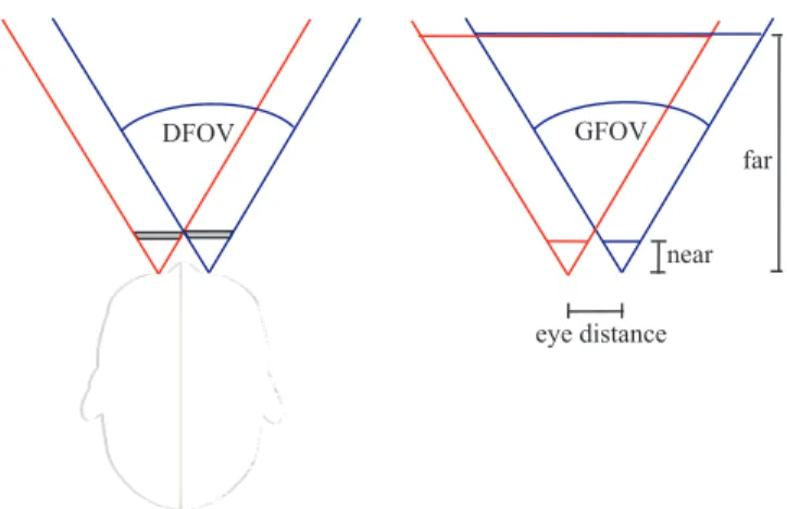
DFOV GFOV
near far
eye distance
Fig. 1. Illustration of the relationship between (left) the DFOV of a HMD and (right) the GFOV used for perspec-tive rendering. Together with the near and far plane the GFOV define the perspective view frustum.
This FOV refers to the horizontal and vertical angles subtended by the display–sometimes referred to as
dis-play field of view (DFOV) (see Figure 1 (left)). Usually
a larger DFOV results in a greater sense of immersion and better situational awareness. However, most HMDs do not cover the entire visual field of the human eyes and support only a considerably smaller field of view. Commercially available HMDs typically have fields of view which range from 20 to 80 degrees diagonally– some even up to 150 degrees horizontal, whereas the effective visual field of humans is approximately 200 degrees horizontally and 150 degrees vertically [40]. In order for a virtual world to be displayed on a HMD, the computer graphics system must determine which part of the VE is to be viewed by the user.
In contrast to the DFOV, the geometric field of view (GFOV) defines the horizontal and vertical boundaries of the virtual viewing volume along with the aspect ratio (see Figure 1 (right).) With such a setup, user movements measured by the tracker are mapped to the position and orientation of the virtual camera. Usually, tracked head pose changes applied to the virtual camera by means of a one-to-one mapping define the camera’s position and orientation in the VE; the projection of the virtual camera defines the view frustum. In most VR applications a perspective projection is chosen such that depth cues are consistent with a user’s real-world view. Near and far clipping planes define the bounds of the visible scene. The horizontal and vertical geometric fields of view define the angles subtended by the view-port from the center of projection in virtual space or, equivalently, the angle subtended by the camera’s view frustum. As illustrated in Figure 1 (right) usually on-axis stereographic rendering is applied in HMD conditions. The image projected onto the viewport is displayed on both physical screens of the HMD.
If the GFOV matches the DFOV of the HMD, the viewport is mapped from virtual space onto the physical
display in such a way that users are presented with imagery that will have “correct” perspective as illus-trated in Figure 2(b) (assuming that we neglect other distortions of the display device such as pincushion distortion). However, even if the fields of view of the display and the virtual camera frustum as well as the ratios of the display and the virtual viewport match, spatial perception of a virtual world through a HMD varies significantly from the real world. For example, several experiments provide evidence that egocentric distances are perceived as significantly compressed in immersive VEs–in some cases up to 50%–relative to distances perceived in the real world [11], [16], [23], [26], [38], [42], [44]. As experiments have shown, only a small portion of the observed compression can be caused by hardware issues, and an explanation for the larger portion of the effect remains unknown.
1.3 Mini- and Magnification
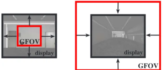
If the GFOV varies from the DFOV, this results either in mini-ormagnificationof the graphics [21] (cf. Appendix). As illustrated in Figure 2(a), if the GFOV is smaller than the DFOV of the HMD, the viewport image will appear magnified on the physical display because of the requirement for the image to fill a larger subtended angle in real space versus virtual space. Conversely, if the GFOV is larger than the DFOV of the HMD, a larger portion of the VE needs to be displayed in the image, which will appear minified (see Figure 2(c)). Depending on the distortion of the geometry of the VE the visual optical flow rate decreases or increases proportionately [6]. The optical flow rate is an essential visual motion pattern that in principle allows humans to extract self-motion information. Hence, manipulation of the GFOV provides a controllable optical distortion resulting in different visual-vestibular patterns in immersive VEs.
In this article we analyze how much mini- or magnifica-tion people prefer when they are able to adjust the per-spective projection in a HMD environment. In particular, we determine how the geometric field of view needs to be specified in a HMD environment such that users have the impression that virtual and real perspectives match. The article is structured as follows. Section 2 summarizes work related to our approach. Section 3 in-troduces a psychophysical calibration method to identify the DFOV. In the first experiment described in Section 4 we used a virtual one-to-one copy of our real laboratory surroundings, and subjects had to adjust the perspective projection until they felt confident that the perspective of the displayed scene matched the perspective in the real laboratory. Section 5 presents a second experiment in which we analyzed the impact of a reduced field of view in the real-world on the subject’s judgement of a natural GFOV in a VE. Section 6 discusses the results
(a)gF = 0.8 (b)gF= 1.0 (c)gF = 1.2
Fig. 2. Illustration of different perspective projections in a virtual 3D model of our laboratory: with a GFOV (a) larger than (b) identical to and (c) smaller than the DFOV. The top row shows the virtual laboratory and the camera frustums from a top-down view, the bottom row shows the corresponding renderings of the laboratory with GFOVs which have been manipulated with gains of (a)gF = 0.8, (b)gF = 1.0and (c)gF = 1.2.
of the experiments as well as implications about how to set up the virtual perspective in HMD environments. Section 7 concludes the paper and gives an overview about future work. Some of the results presented in this article have been presented in [37].
2
R
ELATEDW
ORKIt is a challenging task to project virtual objects on a planar display surface in such a way that metric properties of objects are perceived correctly by human observers. In order to extract three-dimensional depth, size and shape cues about virtual objects from planar representations, the human visual system combines var-ious different sources of information [27]. Since two-dimensional pictorial or monocular depth cues, e. g., linear perspective, are interpreted by the visual system as three-dimensional depth, the information they present may be ambiguous [18]. These ambiguities make it dif-ficult to extract correct depth cues and are intentionally introduced in many common optical illusions [9].
View Frustums
The perspective view frustum defines the three-dimensional volume in space, which is projected to the image plane. As illustrated in Figure 1 (right), a view frustum can be specified in view space by the distances of the near (near ∈ R+) and far (far ∈ R+) clipping
planes, and the extents of the projection area on the near plane (left, right, top, bottom ∈ R) [35]. Alternatively, a
symmetrical view frustum can be specified using only the vertical angle of the geometric field of view:
GFOV= 2·atan top near ∈ 0,180, (1)
and the image ratio (ratio∈R+).
The nominal DFOV of a HMD can be derived by the width (w) and the height (h) of the displays specified by the manufacturers, and the distance (d) of the eyes to the displays. Assuming a symmetrical view frustum, the vertical DFOV can be calculated with the following equation: DFOV= 2·atan h 2·d , (2)
and the horizontal DFOV can be calculated by replacing hbywin equation (2).
Since most commercially available HMDs have rela-tively narrow fields of view in comparison to the effec-tive visual field of humans, HMD users can see only a rather restricted portion of the virtual world if the GFOV matches the DFOV of the HMD. In the real world, a narrow field of vision has been shown to degrade spatial awareness and human performance in navigation and manipulation tasks [17], [13] as well as visual search tasks [3]. There has been much evidence that a restricted FOV in the virtual world may lead to perceptual, visual, and motor decrements in various kinds of performance tasks [1], [12].
Mini- and Magnification
As mentioned in Section 1.2, if the GFOV matches the DFOV, the viewport is mapped directly from virtual space onto the physical display, and therefore users
are presented with imagery that will have a “correct” perspective. However, a deviation between the GFOV and the DFOV occurs, for example, when the actual DFOV varies from the nominal values specified by the HMD manufacturers. A deviation can also be induced intentionally. Sometimes VR application developers use a larger GFOV in order to provide a wider view to the virtual world. Such deviations result in minification of the graphics (cf. Appendix). Choosing an extremely large field of view may not always be optimal, since the required GFOV for a HMD mainly depends on the application under consideration. If the GFOV is larger than the DFOV of the HMD, any given object drawn to the screen will cover fewer pixels in the screen as the GFOV is increased. Furthermore, a large GFOV may be unnecessary for tasks, which are localized within a small spatial region of interest [13], and it may aggravate simulator sickness effects, particularly those caused by vection and visual-vestibular mismatch [34], [36].
However, an increased GFOV allows for the inclusion of more information in the 3D view like a larger physical display would. A larger DFOV is essential in some ap-plications and has the potential to improve and increase the user’s sense of presence [2], [34]. Similar benefits may also occur if a large GFOV is used with a display that has a small DFOV. Several works have introduced these deviations in order to address limitations of small dis-play spaces in two-dimensional desktop environments, for example using Fish-Eye views [8].
Scene Perception
Mini- or magnification changes several visual cues that provide information about metric properties of objects such as distances, sizes, shapes and angles [18]. How-ever, even if the GFOV and DFOV match, people’s ceptions and actions in the VE may differ from their per-ceptions and actions in an equivalent real environment. Many studies that compared distance perception of static targets in immersive VEs and in the real world found evidence that distances are perceived as compressed in VEs relative to the real world [11], [26], [42], [43]. It has been shown that as long as HMD users look around in a real or virtual environment, a restricted field of view (e. g., a 60degree diagonal DFOV) did not change their behavior on blind walking distance estimation tasks [4], [19]. However, previous studies have suggested that physical factors related to the ergonomics of head-mounted displays may account for some of the apparent compression [19], [22], [21], [38], [41].
However, an explanation for the larger portion of the observed compression effects remains unknown. Given that underestimation has been found in a number of studies using HMDs and that HMDs typically have a reduced FOV, the restricted field of view has been sus-pected as a factor influencing distance perception [30], [43]. Increasing the GFOV of a VE may be one way to compensate for the restricted DFOV.
Although researchers have investigated the effects of the GFOV on performance and level of presence experi-enced [15], few studies have explicitly considered the re-lationship between GFOV and the DFOV of HMDs [45]. In the experiments described by Kuhl et al. [21] subjects saw the virtual world with a FOV that was larger (20%) than the one provided by the HMD resulting in minification of the graphics. In this case, the typical spatial compression effects in direct blind walking tasks in VEs were reduced, i. e., subjects walked significantly farther to previously seen targets when the graphics were minified. On the other hand, magnification changes these cues in the opposite direction and can potentially decrease perceived distance. The benefits of distorting the GFOV are not clear [37]. A series of studies were conducted to evaluate the role of the GFOV in accurate spatial judgments. It has been shown that when subjects perceive proprioceptive and tactile feedback, the GFOV can be increased without causing a significant distortion in the user’s distance perception [45]. Relative azimuth and elevation judgments in a perspective projection were less accurate for GFOVs greater than the DFOV [25]. This effect has been noted in see-through stereoscopic displays that match real-world viewing with synthetic elements [32]. Alternatively, room size estimation tasks and distance estimation tasks were aided by a larger GFOV [28]. The sense of presence also appears to be linked to an increased GFOV [14]. For other tasks, like estimating the relative skew of two lines, a disparity between DFOV and GFOVs was less useful [33].
3
P
SYCHOPHYSICALC
ALIBRATION OFGFOV
As mentioned in Section 2, the DFOV of a HMD may vary from the nominal values specified by the manu-facturer. In this section we describe a psychophysical calibration method for HMDs that allows to determine the DFOV. Usually, the nominal DFOV for HMDs is specified as visual angle across the diagonal of a display.1 Since most graphics systems require the horizontal and vertical (instead of the diagonal) fields of view of the display, almost all HMD users convert the nominal diagonal DFOV into geometric horizontal and vertical fields of view, often assuming a square-pixel aspect ratio. However, according to Kuhl et al. [21], the horizontal and vertical geometric fields of view determined in such a way can fail to match the DFOV of the HMD for three reasons:
1) The nominal diagonal DFOV may differ from the display’s actual diagonal DFOV.
2) The actual aspect ratio of the display may not match the ratio of horizontal to vertical pixel counts.
3) Pincushion distortion may lead to different FOV values.
1. For simplicity, we refer to GFOV and DFOV as the diagonal fields of view, if not stated otherwise.
In order to account for the three sources of error, differ-ent calibration methods have been proposed to iddiffer-entify the DFOV of a HMD [24]. Ellis and Nemire [7], [29] displayed vertical poles in the HMD. When wearing the HMD, subjects had to point at the perceived location of the poles in the real world. This allowed the researchers to calculate how the GFOV has to be specified so that the virtual angles and pointed angles match. Another method [31] uses a strobe light to provide subjects with an afterimage of a known visual angle. When wearing the HMD, subjects used this afterimage to measure the FOV of the display. It may also be possible to calibrate non-see-through HMDs by adapting methods used for see-through display calibration [10]. Another simple cal-ibration approach requires VR users to adjust the GFOV by comparing a real object with a virtual object by constantly raising and lowering the HMD [21]. In the fol-lowing we describe a psychophysical calibration method to identify the DFOV of a HMD in a more precise way in comparison to previously described methods.
Psychophysics is an area of perceptual psychology that employs specific behavioral methods to study the relation between stimulus intensity and perception re-ported by a human observer. The amount of change in a stimulus required to produce a noticeable sensation is defined as the just noticeable difference (JND). In the calibration process discussed here, subjects had to report their judgments of different GFOVs based on a two-alternative forced-choice task (2-AFCT). In order to manipu-late the GFOV we applyfield of view gainsgF[x]∈R+and gF[y] ∈ R+ to the virtual camera frustum by replacing
the horizontal angle fovx and the vertical angle fovy of the geometric field of view by gF[x]·fovxandgF[y]·fovy, respectively.
In the psychophysical calibration process described in this section, we used the method of constant stimuli, i. e., the presented stimuli were not related from one trial to the next, but presented randomly and uniformly distributed. After the visual stimuli had been presented, a participant had to choose between one of two possi-ble responses, i. e., “Do you think the virtual world is minified ormagnified?”; responses like “I can’t tell.” were not allowed. In this method, when the participant cannot detect the signal, he must guess, and on average he will be correct in50% of the trials. Participants were trained as to what “minified” and “magnified” means in this context.
The gain at which a subject responds “minified” in half of the trials is taken as the point of subjective equality (PSE), at which the subject perceives both stimuli as identical. As the gain decreases or increases from this value the ability of the subject to detect a difference be-tween both stimuli increases, resulting in a psychometric curve for the discrimination performance. Thresholds are those points of intensity at which subjects can just de-tect a discrepancy between physical and virtual stimuli. Usually the points at which the curve reaches the middle between the chance level and 100% correct estimations
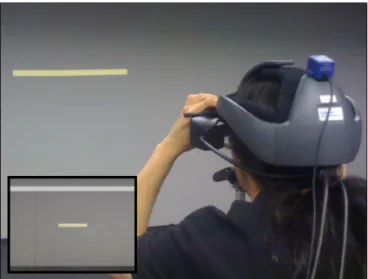
Fig. 3. Picture taken during the psychophysical calibra-tion process. A participant at a fixed posicalibra-tion compares the size of the horizontal stripe in the real world with the virtual stripe displayed on the HMD (see inset).
are taken as thresholds. We define thedetection threshold (DT)for gains smaller than the PSE to be the value of the gain at which the subject has75%probability of choosing the “magnified” response correctly, and the detection threshold for gains greater than the PSE to be the value of the gain at which the subject chooses the “magnified” response in only25% of the trials. The correct response “minified” was then chosen in75% of the trials.
3.1 Material and Methods
Two members of the computer science department with much HMD experience participated in the calibration process. Both had normal or corrected to normal vision. The total time per participant took 1 hour. We per-formed the calibration process in a 10m×7m darkened laboratory room. We used two HMDs for the stimulus presentation: (1) Rockwell Collins ProView SR80 (1280 × 1024 @ 60Hz, 80◦ diagonal DFOV), and (2) eMagin Z800 (800 ×600 @ 60Hz, 40◦ diagonal DFOV). On top of each HMD an infrared LED was fixed. We tracked the position of the LED within the room with an ac-tive optical tracking system (Precise Position Tracking of World Viz), which provides sub-millimeter precision and sub-centimeter accuracy. The update rate was60Hz providing real-time positional data of the active mark-ers. For three degrees of freedom orientation tracking we used an InertiaCube 2 (InterSense) with an update rate of 180Hz. The InertiaCube was also fixed on top of the HMD. An Intel computer (dual-core processors, 4GB RAM, nVidia GeForce 8800) displayed the VE and was used for system control and logging purposes. The virtual scene was rendered using OpenGL and our own software with which the system maintained a frame rate of60frames per second. In order to focus participants on the tasks no communication between experimenter and
participant was performed during the experiment. The participants received instructions on slides presented on the HMD. A Nintendo WII remote controller served as an input device via which the participant judged his comparison between virtual and real perspective.
The visual stimuli consisted of a virtual 3D model of the real laboratory (see Figure 2). We modeled this virtual replica as a set of texture-mapped polygons. The texture maps were obtained from a mosaic of digital photographs of the walls, ceiling and floor of the labo-ratory. All floor and wall fixtures were represented true to original as detailed, textured 3D objects, e. g., door knobs, furniture and computer equipment.
During the calibration procedure, the participants faced a wall of the laboratory with their heads mounted in a fixed position at a distance of3m from the wall (see Figure 3). In the virtual world we displayed consecu-tively a horizontal respecconsecu-tively vertical1m×0.05m stripe on the wall, in the real world we taped corresponding stripes onto the wall. The participants compared the real-world stripes with the stripes displayed in the HMD by repeatedly raising and lowering the HMD on their head. Then the participants had to judge whether the virtual stripe was displayed minified or magnified compared to the real-world stripe based on a 2-AFCT. We tested both the ProView and the eMagin HMD with a horizon-tal and a vertical stripe consecutively. We manipulated the GFOV with different gains gF[x] and gF[y] ranging between 0.90 and 1.10 in steps of 0.01 applied to the horizontal and vertical angles of the HMDs, which we computed from the diagonal DFOV specified by the manufacturers (cf. Appendix). We presented the gains in randomized order, each gain occurring10times. Figure 3 shows a participant in the physical laboratory, who compares the horizontal virtual stripe in the 3D model with the stripe in the real world.
3.2 Results
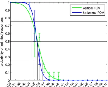
Figure 4 plots the mean probability for a participant’s estimation that the virtual horizontal/vertical stripe was displayed minified against the tested gains for the ProView SR80 HMD. The solid lines show the fitted psychometric functions of the formf(x) = 1
1+ea·x+b with
real numbers a and b. The green line corresponds to the participants’ pooled results for the ProView SR80 for the vertical FOV, the blue line corresponds to the participants’ results for the horizontal FOV. The error bars show the standard errors. The results show that participants are quite good at discriminating between vertical and horizontal real and minified/magnified vir-tual stripes. The PSEs in the experiment approximate gF[x] = 0.9548 and gF[y] = 0.9562 for the ProView HMD. This means that the aspect ratio of the display as perceived by the participants approximates the ratio of horizontal to vertical pixel counts, i. e., a ratio of1.243 in-stead of 1280/1024=1.25. Furthermore, the results show that the DFOV perceived by the participants is slightly
Fig. 4. Pooled results of the discrimination between the DFOV of the HMD’s and the GFOV. The horizontal axis shows the gains applied to the GFOV, the vertical axis shows the probability that subjects estimate the virtual world to be minified compared to the real world.
smaller than the FOV specified by the manufacturers, i. e.,76.88◦ instead of80◦ for the ProView SR80.
Lower and upper detection thresholds for the ProView are given for gains atgF[x] = 0.9491and gF[x] = 0.9606, and gF[y] = 0.9457 and gF[y] = 0.9666. This means that participants cannot notice when the GFOV varies between76.35◦and77.41◦for the80◦diagonal ProView.
The results for the eMagin were similar. The PSEs ap-proximategF[x]= 0.9708and gF[y]= 0.9602, resulting in a FOV of38.72◦ instead of the specified40◦, and a ratio of 1.264 instead of 800/600 ≈ 1.333. Lower and upper detection thresholds for the eMagin are given for gains at gF[x] = 0.9639 and gF[x] = 0.9776, andgF[y] = 0.9518 andgF[y]= 0.9687.
The small JND intervals around the PSEs for both displays show that the participants were quite accurate in detecting a manipulated field of view, so that this cal-ibration method appears reliable to determine a DFOV. Hence, we assume the native DFOV of the ProView SR80 HMD to be76.88◦with a native aspect ratio of1.243. We
use these values to define the perspective projection in the experiment described in Section 4.
In most graphics systems only the vertical field of view is specified in order to set up the perspective projection; the horizontal angle is derived using the aspect ratio. Hence, in the following we will focus on fovy, and for simplicity we will denote the gain applied to the vertical field of view of the display by gF ∈ R+, if not stated
differently. Hence, in order to manipulate the perspective projection, we render the scene with a GFOV defined by the display’s actual vertical FOV multiplied with the gaingF. IfgF = 1the DFOV of the HMD and the GFOV used for rendering are identical (cf. Figure 2(b)), ifgF <1 the used GFOV is smaller than the DFOV and the virtual
Fig. 5. Photo from the experiment showing a subject with the ProView SR80 HMD adjusting the GFOV with the PowerMate.
world is magnified (cf. Figure 2(a)), and if gF > 1 the GFOV is increased and the virtual world is minified (cf. Figure 2(c)).
4
E
XPERIMENT1 (E1): J
UDGMENT OFN
ATURALP
ERSPECTIVEP
ROJECTIONSIn this section we describe the experiment that we con-ducted to identify the geometric field of view, which sub-jects reveal as most natural, i. e., the GFOV from which they estimate that it matches the real-world perspective. We performed the experiment in almost the same setup as described in Section 3. For the experiment E1 we used the ProView SR80 HMD with the results from the calibration process, i. e., we assumed an actual diagonal DFOV of 76.88 degrees and an actual aspect ratio of 1.243. In order to determine the most natural perspective projection, subjects could change the GFOV of the virtual scene by changing the gain gF that we applied to the actual vertical geometric field of view, while preserving the aspect ratio as described in Section 3.2. Hence, for gF = 1.0 the horizontal and vertical GFOV correspond to the display’s actual fields of view that we have identified using the psychophysical calibration method (cf. Section 3).
Participants
2 female and 9 male (age 23-46, ∅: 28.8) subjects
par-ticipated in the experiment E1. Subjects were students or members of the computer science, mathematics, psy-chology, geoinformatics, and physics departments. All had normal or corrected to normal vision; three wore glasses or contact lenses. Five of the subjects had expe-rience with walking in VR environments using a HMD setup. Four had much video game experience, four some,
and three none. Two of the authors participated in the study, all other subjects were na¨ıve to the experimental conditions. The total time per subject including pre-questionnaire, instructions, training, experiment, breaks, and debriefing took1hour. Subjects were allowed to take breaks at any time.
4.1 Material and Methods
We used a within-subject design in this experiment. At the beginning of the experiment, each subject was positioned in the center of the laboratory. Each subject was instructed to visualize and memorize the size of the laboratory as well as the sizes of objects within the laboratory, e. g., chairs, doors and cupboards. Therefore, subjects were allowed to move around the laboratory for a short period of time. After two minutes, a subject had to put on the HMD which immediately displayed a virtual view of the one-to-one virtual replica of the real laboratory with respect to the subject’s tracked position and orientation in the real laboratory. In the subsequent trials a subject’s task was to adjust the geometric field of view until the subject evaluated the GFOV as most natural, i. e., that it matched the real perspective. In order to do so, subjects could adjust the gain gF, which we used as a factor for the display’s vertical FOV to compute the vertical GFOV, from which in turn we computed the horizontal GFOV using the display’s aspect ratio (cf. Section 3.2). To change the gain gF, subjects used a PowerMate USB multimedia controller manufactured by Griffin Technology (see Figure 5). Clockwise rota-tions of the wheel increased the gain gF by 0.01 per 3 degrees, counterclockwise rotations decreased the gain by the same amount in the other direction. Subjects were allowed to walk around in the virtual replica and compare different cues until they were confident that the adjusted GFOV matched the real-world perspective. Then they had to push the button on the PowerMate to indicate the end of the trial. After that we displayed a bright white image on the HMD, which faded to black in 3 seconds before the new trial started. We used this transition effect to prevent subjects from comparing the visual stimuli of two subsequent trials, for example, by comparing borders or edges of the virtual laboratory.
We simulated fields of view of different HMDs by scaling the viewport during the rendering process, i. e., a part of the display was blackened and the remaining area in the center of the display was used for rendering. Using this software-based approach we simulated DFOVs of 20, 40, 60 and 76.88 degrees (the ProView’s DFOV as derived from the calibration process). Each of these DFOVs was tested 10 times in randomized order, of which five trials started with a gain gF = 1.5 and five trials with a gaingF = 0.5.
4.2 Results
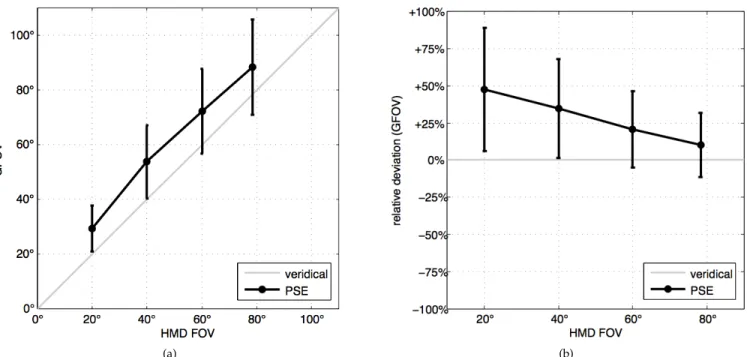
Figure 6(a) plots the DFOVs against the subjects’ ad-justment for the most natural geometric fields of view.
(a) (b)
Fig. 6. Pooled results of the experiment showing the different simulated displays’ fields of view on the horizontal axis plotted against (a) the absolute GFOVs and (b) the relative deviation of the GFOVs from the display’s FOV on the vertical axis.
Figure 6(b) shows the relative deviation of the GFOVs from the displays’ actual fields of view. The black cir-cles represent the PSEs, i. e., the GFOVs that subjects perceived as natural. The error bars show the standard errors pooled over all subjects. There was no difference between starting a trial with an initial gain gF = 1.5 or gF = 0.5, so we pooled the results for these two conditions. The results show that the subjects’ average judgment of a “natural” GFOV deviates significantly from the actual display’s FOV, especially for small FOVs. The PSEs in the experiment are given at a diagonal geometric field of view of 29.53◦ for a HMD with a
diagonal DFOV of 20◦, 53.85◦ (40◦), 72.33◦ (60◦), and 88.34◦ (76.88◦). The results show that the geometric field of view which appears most natural to the subjects is larger than the display’s field of view. In Figure 6(b) it is pointed out that subjects adjusted the GFOV approxi-mately 47.66% larger than the display’s field of view in the case that the HMD’s DFOV equals20◦. In the other cases the geometric fields of view were adjusted 34.63% (40◦), 20.55% (60◦), and 12.68% (78.4◦) larger than the DFOV.
From the subjects’ answers we computed lower and upper thresholds at the points of intensity around the PSEs where subjects answered with 75% probability that the presented perspective projections were natural. These thresholds define a range of gains which appear natural to users in 75%of the time. Hence, gains within this range can be applied in HMD environments without subjects noticing a discrepancy between the display’s FOV and the GFOV used for rendering the VE. For a HMD with 20◦ diagonal field of view the lower and
upper thresholds for GFOVs are 23.40◦ and 34.20◦. For the other simulated fields of view the lower and up-per thresholds are 45.40◦ and 59.40◦ (40◦), 60.00◦ and 80.40◦ (60◦), and77.60◦ and98.40◦(78.4◦). The intervals around the PSEs for the different FOVs show that the subjects’ judgment of a “natural” FOV shifts towards larger GFOVs for HMDs with a small FOV. The results further show that the subjects’ judgment of a natural GFOV approximates the DFOV for HMDs with a larger FOV. The results for the two expert users who performed the calibration (as described in Section 3) did not vary significantly from the other subjects.
In summary, the results motivate that the GFOV should be increased for HMDs with a small geometric field of view in order to appear more natural to users. Even when the geometric field of view is further in-creased within the gain interval of the detection thresh-olds the corresponding perspective projection appears still natural.
We measured the subjects’ self-reported sense of pres-ence in the displayed virtual world using the Slater-Usoh-Steed (SUS) presence questionnaire [39]. Subjects rated their sense of presence on average with a SUS score of 4.52. Subjects further judged the difficulty of the task with0.75on average on a 5-point Likert-scale (0 corresponds to very easy,4corresponds to very difficult). On a comparable Likert-scale subjects reported their fear of colliding with physical objects during immersion on average as0.5, which shows that subjects felt quite safe, probably because the virtual scene showed a co-located and detailed virtual replica of the subjects’ physical surroundings. Draper et al. [6] have reported increased
simulator sickness when manipulating GFOVs. Hence we also considered effects of the different gains on simulator sickness. Simulator sickness is an important, but common issue of VR systems, in particular in HMD experiments over a long period of time. We measured simulator sickness by means of Kennedy’s Simulator Sickness Questionnaire (SSQ). The pre-experiment SSQ score averages to 4.86 and the Post-SSQ score to 13.09. There was no significant increase on simulator sick-ness caused by the experimental task and manipulated GFOVs in comparison to HMD experiments that we have previously performed in our laboratory. The pre-recorded panorama images used by Draper et al. [6] as visual stimulus instead of a visually faithful virtual scene may have led to the increase observed in their experiments.
5
E
XPERIMENT2 (E2): I
NFLUENCE OFF
IELD OFV
IEWD
ISCREPANCIESDuring the real-world situation at the beginning of the experiment E1 described in Section 4 and [37] subjects could use the entire visual angle of their eyes to view the real-world laboratory. Afterwards, when wearing the HMD this field of view was limited due to the properties of the HMD. The subjects’ overestimations of a natural FOV might have been effected by this difference since they compared the limited view to the virtual laboratory with an unlimited view to the real laboratory. In order to examine if this unlimited view has affected the subjects’ judgements we performed a second experiment.
5.1 Material and Methods
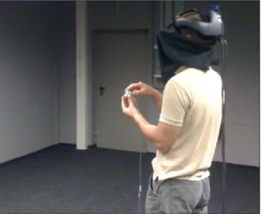
We used the same within-subject design in the exper-iment E2. In contrast to the experexper-iment E1 (described in Section 4) subjects were equipped with a physical view restriction to simulate a limited field of view in the real world. Therefore, we disassembled a pair of passive stereo glasses and adapted them in such a way that subjects were able to view the laboratory through a peephole with an effective vertical field of view of 20 degrees for each eye (see Figure 7) and a ratio of 4/3. We tested only a view restriction of 20 degrees since this was the largest difference between the visual angle of the eyes and the limited viewing condition in our experiment. For this experiment we chose only subjects who had not seen the VR laboratory before the experiment. They were equipped with the view limiting glasses outside the laboratory. We calibrated the glasses for each subject by positioning subjects at a distance of 2m from a wall. We attached a stripe to the wall with a length of 1.73m and told the subjects to adjust the glasses until the stripe fitted entirely into the view. Then, a subject was guided to the center of the real laboratory. The remainder of this experiment was performed similar to the experiment E1 described in Section 4. Each subject was instructed to visualize and memorize the size of
Fig. 7. Photo of a user with a view restriction. The glasses limit the field of view to20◦. During the experiment a cloth was attached to the glasses to avoid that subjects could perceive visual information from beyond the glasses.
the laboratory as well as the sizes of objects within the laboratory, e. g., chairs, doors and cupboards. Therefore, subjects were allowed to move around the laboratory for 2 minutes.
Afterwards, each subject was guided outside the lab-oratory and had to put on the HMD which displayed a virtual view of the one-to-one virtual replica of the real laboratory with respect to the subject’s tracked position and orientation in the real laboratory. Hence, we ensured that the subjects were able to view the real laboratory only with a restricted field of view.
As described in Section 4.1 subjects were equipped with a PowerMate input device to adjust the geometric field of view until they thought the view matched the view to the previously experienced real-world situation with a limited field of view. We tested the smallest GFOV of 20 degrees. We tested this FOV 10 times, five trials started with a gain gF = 1.5 and five trials with a gain gF = 0.5.
Participants
10male (age 23-38,∅: 28.5) subjects participated in the
experiment E2. None of the subjects had seen the labo-ratory before the experiment. Subjects were students or members of the computer science, mathematics, psychol-ogy, geoinformatics, and physics departments. All had normal or corrected to normal vision; three wore glasses or contact lenses. Four of the subjects had experience with walking in VR environments using a HMD setup. Three had much video game experience, four some, and three none. All subjects were na¨ıve to the experimental conditions. The total time per subject including pre-questionnaire, instructions, training, experiment, breaks, and debriefing took one hour. Subjects were allowed to take breaks at any time.
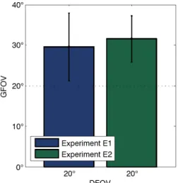
Fig. 8. Pooled results of experiments E1 and E2 showing the displays’ fields of view (20◦) on the horizontal axis plotted against the GFOVs on the vertical axis.
5.2 Results
Figure 8 plots the DFOV of 20◦ against the subjects’ adjustment for the most natural geometric field of view (left) for the unlimited real-world viewing condition (cf. experiment E1) and (right) the limited real-world viewing condition. The bars represent the PSEs, i. e., the GFOVs that subjects perceived as natural. The error bars show the standard errors pooled over all subjects. There was no difference between starting a trial with an initial gain gF = 1.5 or gF = 0.5, so we pooled the results for these two conditions.
The results show that the subjects’ average judgment of a “natural” GFOV deviates significantly from the tested DFOV of20◦. The PSE in this experiment is given
at a diagonal geometric field of view of 31.5360◦ for a HMD with a diagonal DFOV of20◦. This corresponds to an overestimation of57.6799% (SD= 28.53,SE= 9.02). The results show that the geometric field of view which appears most natural to the subjects is larger than the display’s field of view.
From the subjects’ answers we computed lower and upper thresholds at the points of intensity around the PSEs where subjects answered with75%probability that the presented perspective projections were natural (cf. Section 4.2). In this experiment for a HMD with 20◦ diagonal field of view the lower and upper thresholds for GFOVs are 23.70◦ and 38.80◦.
We used a t-test analysis to reveal whether or not the results from this experiment significantly deviate from the findings of the experiment E1 described in Section 4. There was no statistically significant difference in the judgements between subjects, who inspected the real laboratory with a limited field of view and those sub-jects, who viewed the laboratory without view restriction (p >0.46).
In summary, the results of this experiment indicate that the deviation between the real-world visual angle
and the limited field of view caused by the viewing condition in an IVE system cannot explain the subjects’ overestimation of the natural GFOV.
6
D
ISCUSSIONThe psychophysical calibration method described in Sec-tion 3 shows that subjects are quite accurate at discrim-inating the DFOV of a HMD from the GFOV used for rendering of the virtual scene when they can compare the virtual view directly with the corresponding view to the real world. However, the experiments described in Section 4 and Section 5 shows that subjects do not nec-essarily estimate a GFOV that is identical to the DFOV as most natural. Subjects tended to judge a significantly larger geometric field of view as natural in case the DFOV was rather small; in some cases up to50%. This observation was confirmed even when the subject’s view to the real laboratory was reduced according to the field of view of the DFOV. One reason for this bias might be that users in HMD environments in general tend to underestimate distances to scene objects visible on the HMD. Since a GFOV that is larger than the DFOV leads to minification of scene objects (cf. Appendix), users might estimate objects to be farther away. Therefore, an increased GFOV may appear more natural in contrast to a GFOV that is identical to the DFOV. When sub-jects have to judge natural perspectives, another reason for the deviation between the display and a geometric field of view might originate in various consciously or subconsciously perceived advantages of a large FOV. As stated above, humans have a much larger field of vision than most HMDs support. With a larger FOV it is easier for humans to detect, localize and acquire visual information about the environment compared to a situation with a more restricted FOV, in which humans have to observe different regions of interest using head movements. The “unnatural” need to rotate the head in order to see objects that would have been in their normal field of vision in the real world also might have influenced their answers. Furthermore, fatigue due to continuously required head movements as well as sim-ulator sickness introduced by latency or inaccuracies in head-tracking may have affected the results and have to be considered carefully. Those influences are underlined by the fact that the deviation between the DFOV and the GFOV adjusted by the subjects increases even more for displays with small FOVs.
In summary, increasing the GFOV by the amount determined in our experiments causes the rendering system to display more information in a user’s view, and furthermore, the user perceives such a distorted perspective projection as more natural in contrast to the situation when the GFOV is identical to the field of view of the display. This result suggests that if a GFOV, which is larger than the DFOV, is intentionally used in some application (for example, to reduce compressed distance judgments [22]), some amounts of distortion will likely go unnoticed by subjects.
7
C
ONCLUSION ANDF
UTUREW
ORKIn this article we have presented a psychophysical cal-ibration method that allows to determine the DFOV of a HMD as perceived by users, and we have conducted two experiments to identify geometric fields of view that appear most natural to users in such a HMD environ-ment. We found that the GFOVs users judge as most natural are not identical to the FOVs supported by the HMDs; for all tested FOVs subjects reported a larger geometric than display’s FOV as natural. We determined how much a GFOV has to deviate from a DFOV in order for subjects to estimate the virtual perspective projection as natural. We believe that increasing the GFOV to the point where users perceive the perspective as most natural–though this may lead to perspective distortions that influence the perceived size of objects, distances and optical flow patterns–has the potential to enhance the overall VR experience. Increased GFOVs afford more information into the limited field of view of a HMD, which leads to more visual information in a user’s view. Furthermore, it has been shown that a larger field of view (resulting in an increased overlap of visual information during camera motions) supports a user’s ability to form a cognitive map of unknown virtual worlds [5]. Kuhl et al. [21] further showed that slightly increased GFOVs and the resulting minification of the displayed graphics (compared to a view from the real world) reduces the distance compression effects in VEs. We compared the results of different tested FOVs, and we found that the PSEs between a DFOV and GFOV are shifted towards increased GFOVs for HMDs with a small FOV. The results provide interesting insights for the specification of GFOVs in HMD environments. In order to render a VE so that the scene appears most natural to users, for HMDs with 20◦ diagonal DFOV the GFOV should be set to 29.53◦ , respectively 53.85◦ for HMDs with 40◦ diagonal DFOV, 72.33◦ for HMDs with60◦DFOV, and88.34◦for HMDs with76.88◦ DFOV (the largest DFOV we have tested). However, in certain situations the geometric field of view desired by users may be much larger in order to get a better impression of an unknown VE or even smaller, since in this case the display resolution is increased because less pixels are mapped to the same display area. It is a challenging question whether the display’s optimal field of view for arbitrary environments and situations can be predetermined. In the future we will pursue these questions more deeply and explore the effects of geometric fields of view, which deviate from displays’ FOVs, on spatial perception in VEs. In particular, we will examine in how far the increased geometric fields of view, which appear natural to VR users, reduce distance compression effects, when the virtual world is displayed with a corresponding perspective projection.
8
A
CKNOWLEDGMENTSThe authors of this work are supported by the Ger-man Science Foundation DFG 29160938, DFG 29160962, DFG LA-952/3 and DFG LA-952/4, the German Federal Ministry of Education and Research project Visuo-spatial Cognition, and the EC Project Eyeshots.
A
PPENDIXThe nominal field of view for most HMDs is specified by the manufacturers as visual angleαacross the diag-onal of the screen with a given aspect ratio in screen space denoted by ratio. Assuming a symmetrical view frustum, the horizontal and vertical fields of view fovx and fovy can then be calculated with equations (3) and (4): fovx= 2·atan tan(α/2) q 1 +ratio1 2 (3) fovy= 2·atan tan(α/2) √ 1 +ratio2 (4) In a computer graphics system usually only the ver-tical geometric field of view (fovy) has to be specified from which the vertical extent of the near plane is calculated, and then the horizontal extent of the near plane is derived using theratio. Mini- or magnification of the graphics is caused by changing the size of the near plane, e. g., by adjusting the vertical and horizontal geometric field of view (see Figure 9). As stated above such a mini- or magnification changes several visual cues that provide distance information. In particular, minification changes three specific cues in a way that can potentially increase perceived distances to objects [20]: (1) it reduces the visual angle, (2) familiar size cues may make objects appear more distant, and (3) minification causes binocular convergence to indicate that objects are more distant. On the other hand, magnification changes these cues in an opposite direction and can potentially decrease perceived distance.
The described mini- and magnification can be imple-mented as follows. Letfovydenote the vertical geometric field of view before mini- or magnification. We assume that the horizontal geometric field of viewfovxis defined according to theratio. Iffovyis scaled by a gaingF (and fovxis modified accordingly using ratio), we can deter-mine the amountm of mini- respectively magnification with the following equation:
m= tan(fovy/2) tan((gF·fovy)/2)
(5) As illustrated in Figure 9, the mini-/magnificationm denotes the amount of uniform scaling that is required to map the viewport (rendered with a certain GFOV) to the display (defined by its DFOV and ratio). If this mini-/magnification equals1.0, a person will perceive a
GFOV GFOV
display display
Fig. 9. Illustration of the relationship between the dis-play’s FOV and the viewport, and the GFOV used for perspective rendering. The left image illustrates a mag-nification (m >1), the right image illustrates a minification (m <1).
spatially accurate image, as defined by the spatial dimen-sions of the virtual space model. When the geometric field of view is increased (gF >1), the resulting image is minified (m <1), whereas a decreased geometric field of view (gF <1) results in a magnified image (m >1).
R
EFERENCES[1] P. L. Alfano and G. F. Michel. Restricting the field of view: Perceptual and performance effects. Perceptual and Motor Skills, 70:35–45, 1996.
[2] R. S. Allison, I. P. Howard, and J. E. Zacherx. Effect of field size, head motion and rotational velocity on roll vection and illusory self-tilt in a tumbling room.Perception, 28:299–306, 1999. [3] K. Arthur. Effects of field of view on task performance with
head-mounted displays. InConference on Human Factors in Computing Systems, pages 29 – 30, 1996.
[4] S. H. Creem-Regehr, P. Willemsen, A. A. Gooch, and W. B. Thompson. The influcences of restricted viewing conditions on egocentric perception: Implications for real and virtual environ-ments. Perception, (34):2, 2005.
[5] H. Dolezal.Living in a world transformed: Perceptual and performa-tory adaptation to visual distortion. Academic Press, 1982. [6] M. H. Draper, E. S. Viirre, T. A. Furness, and V. J. Gawron. Effects
of image scale and system time delay on simulator sickness within head-coupled virtual environments.Human Factors: The Journal of the Human Factors and Ergonomics Society, 43(1):129–146, 2001. [7] S. Ellis and K. Nemire. A subjective technique for calibration
of lines of sight in closed virtual environment viewing systems. Proceedings of Society for Information Display, 1993.
[8] W. G. Furnas. Generalized fisheye views: Visualizing complex information spaces. In Proceedings of CHI, pages 16–23. ACM Press, 1986.
[9] B. Gillam. Geometrical illusions. American Journal of Science, 242:102–111, 1980.
[10] S. Gilson, A. Fitzgibbon, and A. Glennerster. Spatial calibration of an optical see-through head mounted display. Journal of Neuroscience Methods, 173:140–146, 2008.
[11] A. A. Gooch and P. Willemsen. Evaluating space perception in NPR immersive environments. InProceedings of Symposium on Non-Photorealistic Animation and Rendering, pages 105–110, 2002. [12] M. A. Hagen, R. K. Jones, and E. Reed. On a neglected variable
in theories of pictorial perception: Truncation of the visual field. Perception & Psychophysics, 23:326–330, 1978.
[13] S. Hassan, J. Hicks, L. Hao, and K. Turano. What is the minimum field of view required for efficient navigation? Vision Research, 47(16):2115–2123, 2007.
[14] C. Hendrix and W. Barfield. Presence within virtual environments as a function of visual display parameters. Presence: Teleoperators and Virtual Environments, 5(3):274–289, 1996.
[15] C. Hendrix and W. Barfield. Perceptual biases in spatial judge-ments as a function of eyepoint elevation angle and geometric field of view. InProceedings of the European Symposium on Space Environment Control Systems, volume 3, pages 87–109, 2000.
[16] V. Interrante, B. Ries, J. Lindquist, and L. Anderson. Elucidating the Factors that can Facilitate Veridical Spatial Perception in Immersive Virtual Environments. InProceedings of Virtual Reality, pages 11–18. IEEE, 2007.
[17] S. E. M. Jansen, A. Toet, and N. J. Delleman. Effects of horizontal field-of-view restriction on manoeuvring performance through complex structured environments.Proceedings of the 5th symposium on Applied Perception in graphics and Visualization, pages 189–189, 2008.
[18] L. Kjelldahl and M. Prime. A study on how depth perception is affected by different presentation methods of 3d objects on a 2d display.Computers & Graphics, 19(2), 199-202., 19(2):199–202, 1995. [19] J. Knapp and J. Loomis. Limited field of view of head-mounted displays is not the cause of distance underestimation in virtual environments. In 13, editor,Presence: Teleoperators Virtual Environ-ments, volume 5, pages 572–577, 2004.
[20] S. Kuhl, W. Thompson, and S. Creem-Regehr. Minification influ-ences spatial judgments in virtual environments. In Proceedings Symposium on Applied Perception in Graphics and Visualization, pages 15–19, 2006.
[21] S. Kuhl, W. Thompson, and S. Creem-Regehr. HMD calibration and its effects on distance judgments. In Proceedings of the 5th symposium on Applied Perception in Graphics and Visualization, 2008. [22] S. A. Kuhl, W. B. Thompson, and S. H. Creem-Regehr. HMD cal-ibration and its effects on distance judgments. ACM Transactions on Applied Perception, 6(3):1–20, 2009.
[23] J. M. Loomis and J. M. Knapp. Visual perception of egocentric distance in real and virtual environments. InVirtual and adaptive environments, volume Virtual and adaptive environments, pages 21–46. Mahwah, 2003.
[24] E. McGarrity and M. Tuceryan. A method for calibrating see-through head-mounted displays for AR. IEEE Proceedings of International Workshop on Augmented Reality, pages 75–84, 1999. [25] M. McGreevy, C. Ratzlaff, and S. Ellis. Virtual space and
two-dimensional effects in perspective displays. InProceedings of the 21st Annual Conference on Manual Control, 1985.
[26] R. Messing and F. H. Durgin. Distance perception and the visual horizon in head-mounted displays. ACM Transaction on Applied Perception, 2(3):234–250, 2005.
[27] J. Murray. Some perspectives on visual depth perception. In ACM SIGGRAPH Computer Graphics, Special issue on interactive entertainment design, implementation and adrenaline, volume 28, pages 155–157, 1994.
[28] D. C. Neale. Spatial perception in desktop virtual environments. In In Proceedings of Human Factors and Ergonomics, pages 1117– 1121, 1996.
[29] K. Nemire and S. Ellis. Calibration and evaluation of virtual environment displays. In IEEE 1993 Symposium on Research Frontiers in Volume, pages 33–40, 1993.
[30] J. Psotka, S. A. Lewis, and D. King. Effects of field of view on judgments of self-location: Distortions in distance estimations even when the image geometry exactly fits the field of view. Presence: Teleoperators and Virtual Environments, 7(4):352–369, 1998. [31] E. Rinalducci, D. Mapes, S. Cinq-Mars, and K. Higgins. Deter-mining the field of view in HMDs: A psychophysical method. Presence: Teleoperators and Virtual Environments, 5(3):353–356, 1996. [32] J. Rolland, W. Gibson, and D. Ariely. Presence. Towards quantify-ing depth and size perception in virtual environments. Presence, 4(1):24–48, 1995.
[33] C. Rosenberg and W. Barfield. Estimation of spatial distortion as a function of geometric parameters of perspective.IEEE Transactions on Systems, Man and Cybernetic, 25, 1995.
[34] A. F. Seay, D. M. Krum, L. Hodges, and W. Ribarsky. Simulator sickness and presence in a high field-of-view virtual environment. InConference on Human Factors in Computing Systems, pages 784 – 785, 2002.
[35] D. Shreiner. OpenGL Programming Guide: The Official Guide to Learning OpenGL, Versions 3.0 and 3.1 (7th Edition). Addison-Wesley, 2009.
[36] K. M. Stanney and R. S. Kennedy. The psychometrics of cyber-sickness. Communications of the ACM, 40(8):66–68, 1997.
[37] F. Steinicke, G. Bruder, S. Kuhl, P. Willemsen, M. Lappe, and K. Hinrichs. Judgment of natural perspective projections in head-mounted display environments. InProceedings of ACM Symposium on Virtual Reality Software and Technology (VRST), pages 35–42, 2009.
[38] W. B. Thompson, P. Willemsen, A. A. Gooch, S. H. Creem-Regehr, J. M. Loomis, and A. C. Beall. Does the quality of the computer graphics matter when judging distances in visually immersive environments? Presence: Teleoperators and Virtual Environments, 13(5):560–571, 2004.
[39] M. Usoh, E. Catena, S. Arman, and M. Slater. Using presence questionaires in reality. Presence: Teleoperator in Virtual Environ-ments, 9(5):497–503, 1999.
[40] R. Warren and A. H. Wertheim.Perception & Control of Self-Motion. Lawrence Erlbaum Associates, 1990.
[41] P. Willemsen, M. B. Colton, S. Creem-Regehr, and W. B. Thomp-son. The effects of head-mounted display mechanical properties and field-of-view on distance judgments in virtual environments. ACM Transactions on Applied Perception, 2(6), 2009.
[42] P. Willemsen and A. A. Gooch. Perceived egocentric distances in real, image-based, and traditional virtual environments. In Proceedings of the IEEE Virtual Reality, pages 275–276, 2002. [43] B. G. Witmer and P. B. Kline. Judging perceived and traversed
distance in virtual environments.Presence: Teleoperators and Virtual Environments, 7(2):144–167, 1998.
[44] B. G. Witmer and J. W. Sadowski. Nonvisually guided locomotion to a previously viewed target in real and virtual environments. Human Factors, 40(i3):489–484, 1998.
[45] U. Yang and G. J. Kim. Increasing the effective egocentric field of view with proprioceptive and tactile feedback. InProceedings of the IEEE Virtual Reality, pages 27–34, 2004.
Frank Steinickereceived the diploma in math-ematics with a minor in computer science in 2002, and the Ph.D. degree in 2006 in computer science from the University of M ¨unster, Ger-many. He is currently a research associate in the Visualization and Computer Graphics (VisCG) research group at the University of M ¨unster. His research interests include computer graphics and human-computer interaction with focus on virtual reality, as well as perception and cognition in computer-generated environments.
Gerd Bruder received the diploma degree in computer science from the University of M ¨unster in 2009. Currently, he is a Ph.D. student in the VisCG research group at the University of M ¨unster and works in the LOCUI project funded by the German Research Foundation. His re-search interests include computer graphics, VR-based locomotion techniques, human-computer interaction and perception in immersive virtual environments.
Scott Kuhlreceived his Ph.D. in computer sci-ence from University of Utah’s School of Com-puting in 2009. He also has bachelor degrees in computer science and mathematics from Augs-burg College in Minneapolis, Minnesota. He is currently an assistant professor of Computer Science at Michigan Technological University. His research interests include space perception, immersive virtual environments, and computer graphics.
Pete Willemsenearned his Ph.D. in computer science from the University of Iowa in 2000. He continued as a post-doctoral researcher and research assistant professor in the School of Computing at the University of Utah. Currently, he is an associate professor of computer sci-ence at the University of Minnesota Duluth. His research interests are in human-computer inter-action with an emphasis on virtual environments, applied perception in graphics and visualization, and real-time virtual environment simulation.
Markus Lappeholds a Ph.D. in physics from the University of T ¨ubingen, Germany. He did research work on computational and cognitive neuroscience of vision at the MPI of Biological Cybernetics in T ¨ubingen, the National Institutes of Health, Bethesda, USA, and the Department of Biology of the Ruhr-University Bochum, Ger-many. Since 2001 he is a full professor of ex-perimental psychology, and member of the Otto Creutzfeldt Center for Cognitive and Behavioral Neuroscience at the University of M ¨unster.
Klaus Hinrichsreceived the diploma in math-ematics with a minor in computer science from the University of Hannover, Germany, and the PhD degree in 1985 from the Swiss Federal Institute of Technology (ETH) in Zurich. He is a full professor of computer science at the Univer-sity of M ¨unster, Germany. His research interests include visualization, computer graphics, algo-rithms and data structures for geometric compu-tation, and spatial data bases.