Abstract— Common engineering approaches and modelling approaches from software engineering are brought together. For the domain of process automation an implementation oriented approach for an object oriented software development for heterogeneous distributed systems is introduced. Model elements for control are added to UML as well as small-scale patterns for plant automation. Besides large-scale patterns are introduced as well as implementational models. The adoption of UML regarding applied diagrams and stereotypes for process automation will be introduced and evaluated.
I. INTRODUCTION
oday the development of software in plant industry is confronted with an increasing complexity of problems. Traditional engineering procedures, following a centralized cpu concept where software is developed and coded without modeling are overstrained by the challenges of growing requirements and the chances of modern, highly potent hardware.
Within the framework of the research project DisPA (Distributed Process Automation) we created an UML based media for describing, modeling and implementing distributed systems. With UML-PA (UML for process automation) a modeling language is created, which is not new in every integral part, but is a mature customization to fit the needs of automation industry. Although the upcoming standard UML 2.0 has forged progresses in modeling real time systems, an UML profile which is adopted for process automation can improve existing weaknesses in this domain. The UML-PA provides improvements to supply a less ambiguous modeling language for several aspects of process automation. Some ideas are already published elsewhere, but there is still no integrated UML model.
Manuscript received September 15, 2004. This work was supported in part by the Deutsche Forschungsgemeinschaft (German Research Foundation) under Grant VO 937/2-1.
B. Vogel-Heuser is Head of the Chair of Process Control Engineering, faculty of electrical, information and media engineering, University of Wuppertal, D-42119 Wuppertal, Germany, 202-439-1945; fax: +49-202-439-1944 (e-mail: [email protected]).
U. Katzke is with the Chair of Process Control Engineering, address see above (e-mail: [email protected]).
II. REQUIREMENTS
An overview of requirements of process automation is listed in table I [1]. The criteria can be structured regarding process requirements, automation system architecture, and project. In process automation, different kinds of processes are possible. In the following, a brief overview of those categories is given. A process automation system represents a type of process, e.g. batch, continuous, or discrete. Sometimes processes are composed of different process types. They are called hybrid, since they consist of different process kinds. These process types require different control strategies and as a result they require different modeling notation features, e.g. block diagrams or state charts.
Moreover overall requirements are real time, the integration of I/O peripherals directly via a backplane bus
Design and Application of an Engineering
Model for Distributed Process Automation
Uwe Katzke, Birgit Vogel-Heuser,
Member, IEEE
T
TABLE I
OVERVIEW OF REQUIREMENTS IN PROCESS AUTOMATION
Categories / Criteria Functionality / Notation
Aspects
batch (continuous) transfer functions, block
diagrams, differential equation
discrete status model, flow chart,
continuous function chart, Petri Net
process
hybrid continuous and discrete process
distribution, communication, network / central unit different hardware platforms different software platforms heterogeneous or
homogeneous
HMI, diagnostics, no screen
time hard and soft real time; time
and event controlled systems IEC 61131-3 for PLC (embedded system), implementation
Proprietary for DCS; C, C++, Personal Java, Embedded Java, RT Java, Ada95 automation system level of automation In product automation 100%
Qualification Easy to handle for engineers
and technicians Top down design
Modularity, component base, object orientation
System life cycle
Reusability Project
Tool support Along entire life cycle
2005 American Control Conference
system or a field bus and interrupts from the process. Furthermore it is required to describe the automation architecture and the mapping from software to hardware. Multiprocessor systems like VMEbus may be included as well.
Regarding an automation project, there are typically different engineers or technicians involved with different qualification levels and subjects. By that fact, the notation has to be easy to use to a certain level for process, mechanical, and electrical engineers as well as for technicians. A more visionary requirement is to support the entire life cycle with one consistent model, but there should be an appropriate notation for each phase of the project.
Today plant manufacturing industry requires standardized automation devices for automation systems, e.g. PLCs (Programmable Logic Controller), which are programmed in IEC 61131-3 [2] Therefore, the transfer of modeling results into IEC 61131-3 is necessary. The IEC 61131-3 contains languages, which follow a function-oriented or procedural-imperative paradigm. The increasing use of these languages causes a growing dependency on the accepted standard, because existing implemented systems must be expanded and the developers are familiar with the practice of “accustomed” programming techniques.
The cumulative expertise about home made modules allows a limited reuse and orientation. Without the knowledge of the experience from building modules, the acceptance of reusable modules is very low [3].
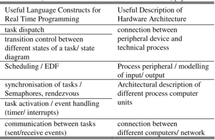
TABLE II REAL TIME REQUIREMENTS
(FUNCTIONAL /IMPLEMENTATIONAL MODEL) [1] Useful Language Constructs for
Real Time Programming
Useful Description of Hardware Architecture task dispatch
transition control between different states of a task/ state diagram
connection between peripheral device and technical process
Scheduling / EDF Process peripheral / modelling
of input/ output synchronisation of tasks /
Semaphores, rendezvous task activation / event handling (timer/ interrupts)
Architectural description of different process computer units
communication between tasks (sent/receive events)
connection between different computers/ network
For special tasks such as safety related tasks or hard real time requirements additional automation devices may be used, such as process control computers with a real time operating system (RTOS). For hard real time systems specific requirements need to be realized. A list of implementation oriented real time requirements is depicted in table II. The aspects of real time development like reactivity, multi-threading, time-based behavior and real time environment need to be met. In the past efficient and machine-intimate but Gordian programming was necessary
to fulfill these requirements. Actual controllers show better performance than their predecessors.
In plant automation, communication between several (embedded) systems is realized via different bus systems. In the level of field control buses like PROFIbus and Interbus are deployed. Whereas the communication between and inside the level of process control, plant management, and enterprise administration normally is based on Ethernet and TCP/IP. For operation and maintenance, a PC-based human machine interface is used. By that fact the architecture of the automation system is heterogeneous.
Prior investigation compared modelling techniques for distributed process control engineering (table I). The research analysed UML and Idiomatic Control Language (ICL) regarding cognitive models and user acceptance [4]. The results of these approaches show the lack in an appropriate accepted modelling technique for the design of plant automation integrating hardware and software as well as architectural aspects (table II)[5]. For automatic code generation a prototype has been developed, which generates IEC 61131-3 code (ST and SFC) automatically from the UML model modelled in an UML tool. This code generation prototype allows to evaluate the weaknesses of standard UML by expert rating [6].
III. NOTATIONS FOR DISTRIBUTED SYSTEMS IN PROCESS
AUTOMATION
UML's advantages, e.g. applicability across different development phases or degree of familiarity among developers as well as users, are also of value in embedded software engineering.
In the following some approaches relevant for embedded systems with real time requirements will be discussed in comparison with this paper. ISILEIT [7] integrates SDL as an extended specification formalism into UML and realizes code generation to Structured Text. The application is neither decentralized nor distributed and the real time requirements are compared with this report weak or soft.
ODEMA [8] provides a UML-based concept without a special focus on distributed real-time systems or the domain of process automation. Braatz strengthened the necessity of automatic code generation for industrial automation as introduced in this paper.
AUTOFOCUS [9] provides a concept of a component oriented architecture combined with a model driven, incremental development process. This approach is dissociated from UML as a complete set of diagram types. Instead the “AutoFocus modeling language & framework” has been created using parts of UML, UML-RT and other common notations. The development process and language support an incremental refinement combined with an increasing detail level of the model. Indeed the targeted
industry (automotive) differs from the requirements of process automation, especially the point of reuse is not worked out.
UML 2.0 [10] specifies with the Profile for Schedulability, Performance and Time Specification [11] some useful constructs for real time systems. But it has no formal semantics as Berkenkötter et al. [12] analyzed. Licht [13] proposed the integration of timed automata, which seems to be a very promising approach, regarding comprehensibility for engineers and formal specification.
Giotto is a programming language for embedded hard-real time control systems with periodic behavior. “Giotto is a domain-specific high-level programming language: domain-specific, as it addresses embedded control applications; high-level, as it abstracts platformdependent implementation details. Giotto-based control systems separate the two concerns (reactivity vs. scheduling; timing vs. functionality)” [14]. The concepts for scheduling and timing aspects need to be evaluated for this project. Giotto worked also on distributed systems, but didn’t focus on process automation specific requirements or large scale software for plants.
Ptomely [15] facilitates functional description by providing various models of computations and hence it allows different domains, but up to now process automation is not included.
Within the framework of DisPA we have created an UML based media for describing, modeling and implementing distributed systems. Based on the requirements analysis a specialized profile of the UML for process automation (UML-PA) has been accomplished and evaluated for hybrid processes and heterogeneous control systems.
IV. ADAPTING UML FOR PROCESS AUTOMATION
(UML-PA)
The adaption of UML for distributed control systems, i.e. modeling of controllers handles time constraints, dynamic redundancy, time triggered synchronization of distributed systems, communication structures between encapsulated modules (from the UML-RT profile), structures for clear multiple inheritance relations and an enlargement of the deployment diagram to describe the mapping of software and hardware architecture. In detail the UML-PA contains the following enhancements:
Time constraints on architectural level Timed Statemachines
Clearness in multiple inheritances
Unambiguous expressions and instructions Communication by ports and protocols and Mapping between software and hardware.
A. Time constraints on architectural level
The UML provides several diagrams for identifying objects and their collaboration. They provide either architectural design (i.e. deployment diagrams) or simple scenarios with real time requirements (i.e. sequence diagrams of UML 2.0). During design many time dependant decisions have to be taken. Engineers need to determine the power of necessary devices as well as their number. Each device will fulfill requirements of other connected devices and their contained processes. Concurrently each device has a limited capacity for fulfilling the claimed requirements.
fieldbus pressure sensor distance controller pressure controller operation mode controller distance sensor valve
closed loop control
(100,8) (100,16) pressure sensor 1 (15) distance controller 1 pressure controller 1 operation mode controller 1 distance sensor 1 (25) valve 1
closed loop control
(100,8) (100,16) pressure sensor distance controller pressure controller operation mode controller distance sensor valve
closed loop control
(100,8) (100,16) pressure sensor n (15) distance controller n pressure controller n operation mode controller n distance sensor n (25) valve n
closed loop control
(100,8) (100,16) (100,16) (100,16)
...
...
(100,8) (100,8)Fig. 1. Communication requirements stress the fieldbus
The load of a certain component (i.e. a fieldbus, fig. 1) is partly given from each connected neighbor. Additionally real time requirements raise the charge. Distributed systems allow parallel execution on different devices. Most single devices operate only sequentially. The different requirements have to be organized by a scheduling.
Fig. 2. Scheduled communication requirements of the fieldbus in a timing diagram (UML 2.0)
The scheduled view (fig. 2) is only a scenario. It is designed from estimated behavior by the experience of engineers. It gives an advice for the composition of the necessary devices. A detailed and traceable view need to be more detailed. This is given by timed statemachines.
B. Timed Statemachines
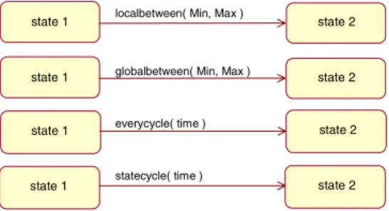
The UML provides only fuzzy defined constructs for the description of real time behavior. Timed statemachines offer a clear media for describing real single and circular time events. Based on the concepts of timed automata [12] certain events and constraints are defined to provide a clear notation for formulating a definite real time behavior.
state 2 state 1 everycycle( time )
state 1 localbetween( Min, Max ) state 2
state 1 globalbetween( Min, Max ) state 2
state 2 state 1 statecycle( time )
Fig. 3. Events of timed statemachines
The events localbetween and globalbetween are forced in the given interval, either after the origin state is reached or after a global defined reference time. The event statecycle occurs periodically and it performs the transition, if the statemachine has reached the origin state. So it is possible to describe processes with edge triggered synchronization. The event everycycle is similar to statecycle, but it demands that the statemachine has reached the origin state. It allows modeling clocked circuits.
C. Clearness in multiple inheritances
Actually multiple inheritances are unpopular, as there is no way to decide competing elements in case of multiple inheritances. The UML-PA offers dominant and subordinate inheritance relations to solve this problem.
class p-controller
dominant inheritance subordinate inheritance
class pi-controller controllfunction
class i-controller controllfunction initialize vp: integer vi: integer
Fig. 4. Domination inheritance
Multiple inheritances are limited to two ancestor classes. The dominant inheritance (marked with a solid dot) inherits as usual all attributes and operations. The subordinate inheritance (marked with an empty dot) only adds undefined items to the inherited class. In the simple example of Fig. 4 the P-controller only inherits the attribute vp, because all other attributes and operations are inherited from class I-controller. This concept is similar to FBS in IEC 61131-3.
D. Unnambiguous expressions and instructions
The UML lacks of well defined notations for the definition of conditions and actions in statemachines. Currently the combination of the used tool and target language determine the rules for the syntax of expressions and single instructions (used as actions in the UML).
E. Communication by ports and protocols
The need of well defined communication is evident in distributed (automation) systems. The first steps when designing a distributed system are embossed by the identification of entities and their interaction. In a process of refinement new entities are generated and applied with additional communication links. These need to be equipped with protocols and the roles of each participant have to be defined. Therefore the UML-PA is supplemented with the extensions ports, capsules, protocols and roles from the UML-RT profile. frame control pressure controller pressure setpoint operation mode controller distance controller pressure sensor distance sensor proportional valve distance setpoint
Fig. 5. First identified entities of the application
Fig. 5 shows the communication dependencies between several entities of a single hydraulic cylinder.
+ controlled system -distance control G iLs GiL Kp TN PICyiL S-set value
Fig. 6. First identified entities of the sample application
incompletely, but the missing parts (i.e. protocols and the links between hardware and software) are modeled in other diagrams. The links between different controllers, sensors and actuators in UML-PA conforms to the presentation of controller links in block diagrams (Fig. 6).
F. Mapping between software and hardware
Deployment diagrams and component diagrams as the current media for modeling relations between hardware and software don’t fit the requirements of process automation. These systems operate with widely distributed hardware.
Identical hardware is used very often at different places. It must be possible to instantiate multiple occurrences of the same hardware, to provide it with its unique record of attributes (i.e. addresses for identification) and to link it to the instance of a connector of the model.
Fig. 6 shows the example application of a continuous fiber board press. It is composed of up to 80 separately controlled frames. Each frame consists of 5 separately controlled cylinders with sensors for pressure and distance. The controllers are situated locally on small single board computers. Each performs a small number of frames. The single board computers, sensors and actuators are physically linked with, e.g. CAN. Beyond it controllers, sensors and actuators are logical linked.
Therefore a specialized object diagram contains model external entities (i.e. hardware entities). Predefined classes for typical hardware objects like sensors, actuators or field busses facilitate the mapping of inputs and outputs to the connectors to the corresponding hardware. The benefits of these UML extensions are demonstrated by implementing a closed loop control system which realizes the press of a fiber board plant as a prototype of an industrial application.
The techniques of multiple inheritances are used to design successive closed loop controller modules (i.e. PI and D controllers) by combining simple units to more complex blocks (i.e. PID controllers). The abstraction level of the object oriented approach allows the construction of virtual devices. They are used to establish a service for the online reconfiguration of a system to displace defective hardware (i.e. sensors). Designed controllers are instances of predefined capsules. The links between different controllers, sensors and actuators in UML-PA conforms to the presentation of controller links in block diagrams.
G. Autoreconfiguration
The reconfiguration service can be used in new or already existing models to improve the functionality (i.e. safety) of target systems. A controller pattern consists usually of a sensor, an actuator and a controller device. The failure of one of the components results in failure of the entire control chain. This safety problem can be prevented by usage of redundant devices. However, the integration of redundant devices into an existing model is one of the main
challenges, often the model structure and also already implemented code have to be changed. An inherited reconfiguration class is designed to solve this problem. It is a virtual representation of a defective device. Any deviation is corrected by an adjustment function (fig. 7).
Sensor Left : Sensor = NULL Right : Sensor = NULL DefectFlag : Boolean Hardware_Relations : Variant GetValuet() : Double SetDefectflag(SetFlag : Boolean) GetNextRight() : Sensor InsertRight(Sr : Sensor) InsertLeft(Sr : Sensor) Virtual_Sensor Distance : Double Assign(Sr : Sensor) SetDistance(NewDistance : Double) Adjustment(InputValue : Double) : Double GetValue() : Double
Fig.7. Virtual_Sensor as an inherited reconfiguration class
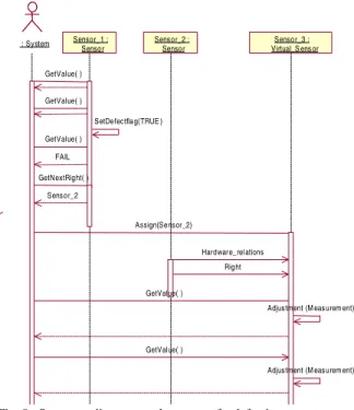
As an example we suppose an additional sensor or an already existing is needed to improve the steadiness of a system, e.g. a sensor. In this case the reconfiguration class will simply replace the primary sensor device. The whole procedure is shown in fig. 8.
: System Sensor_1 : Senso r Sensor_2 : Sensor Sensor_3 : Virtual_S ens or GetValue( ) GetValue( ) SetDefectflag(TRUE ) GetValue( ) FAIL GetNextRight( ) Sensor_2 Assign(Sensor_2) Hardware_rel ations Right GetValue( )
Adjustment (M easurem ent) GetValue( )
Adjustment (M easurem ent)
Fig. 8. Sequence diagram: replacement of a defective sensor
The configuration class Virtual_Sensor instantiates the physically existing device Sensor_2, but it corrects the measurement in a way, that the system’s handling of the substitute is identical to the original device. Therefore the reconfiguration class uses the mechanisms of inheritance and overriding.
V. EVALUATION
The application of a continuous hydraulic press for particle board production has been used to evaluate the UML-PA itself and the developed procedures. Each hydraulic group is controlled by a distributed control device
with several closed loop controllers. Due to global safety constraints some higher-ranking global functions require a synchronized controller switch in all hydraulic groups, i.e. in all distributed systems simultaneously.
The closed loop controls, implemented from the UML-PA model for press control are performed on a simulated process model (Matlab / Simulink) of the press. Both types of systems, the process model and the controller are connected via CAN as fieldbus system. To evaluate reconfiguration using dynamic redundancy (to displace defective hardware) the process model could simulate faulty sensors, which require a replacement of sensors using the sensor data of a neighbor hydraulic system. Bus load is monitored as well as the compliance with timing and the functionality constraints.
VI. SUMMARY
At first we find the successful development of notation elements for open and closed loop control, interlocking and redundant hardware aspects, which are part of characteristic aspects of embedded systems. We designed intuitive applicable elements on the basis of typical modeling constructs in control automation. In addition we show a possibility to bridge the gap between the function oriented paradigm used in plant automation industry and the object oriented approach, which is an important aspect for adoption in industry. This aspect is not at least shown by the usage of reusability.
At this point the presented parts of UML-PA may look fragmental, but the complete UML-PA will bridge the gap between process automation and computer science. The composition of these parts is the result of the detailed requirements analysis, which was made already in the forefront of the UML-PA elements’ development. These requirements are based on one hand on different interviews with software developers and users [5] and on the other hand on the evaluation of UML tools [16].
VII. OUTLOOK
Most UML-PA extensions can be realized through annotations within such tools. Based on the UML code generator the UML-PA should be interpreted. By this it will be implemented in such a tool. To develop distributed systems the timing of bus systems needs to be included in such a model. The integration of tool simulating bus systems, e.g. Ethernet, should be coupled with an UML-PA approach. Outside the scope of this project, but nevertheless an interesting enhancement of software, that is designed using UML-PA are the aspects dynamic reloading during runtime, automatic (re-) configuration and decoupling of software fragments. UML-PA offers promising fundaments to realize such features, due to their supported
characteristics concurrency, structural independence, and immutability (by a third party). The challenge to realize the above mentioned abilities is the required communication infrastructure of the software components. Today, this is usually accomplished by communication interfaces, which are also supported by UML-PA. Reconfigurable software would need additional features like the ability to negotiate with other parties and to dynamically adapt to given needs. Therefore, continuative methods for software development are necessary.
REFERENCES
[1] B. Vogel-Heuser, K. Fischer, P. Göhner, F. Gutbrodt and U. Katzke:
“Conceptual Design of an Engineering Model for Product and Plant
Automation” in Ehrig et al. (Eds.) Integration of Software
Specification Techniques for Applications in Engineering, Lecture Notes of Computer Science, vol. 3147, Springer, Berlin, 2004.
[2] F. Bonfatti, P. D. Monari and U. Sampietri: IEC 1131-3
Programming Methodology. CJ International, Seyssins, 1997.
[3] Stützle, R.: Wiederverwendung ohne Mythos: Empirisch fundierte
Leitlinien für die Entwicklung wiederverwendbarer Software, PhD Thesis, faculty of computer science, University of Munich, 2002.
[4] D. Friedrich, B. Vogel-Heuser and E. Bristol, “Evaluation of
Modeling Notations for Basic Software Engineering in Process Control” in: 29th Annual Conference of the IEEE Industrial Electronics Society (IECON 03) Roanoke, VA, USA, 2003.
[5] U. Katzke, B. Vogel-Heuser and K. Fischer, “Analysis and State of
the Art of Modules in Industrial Automation” in atp international, 2(2004), issue 1, Oldenbourg Verlag, Munich, 2004.
[6] B. Vogel-Heuser, D. Friedrich, U. Katzke and D. Witsch, „Usability
and benefits of UML for plant automation – some research results“ accepted paper ” in atp international, 3(2005), issue 1, Oldenbourg Verlag, Munich, 2005.
[7] U. Nickel, W. Schäfer and A. Zündorf, „Integrative Specification of
Distributed Production Control Systems for Flexible Automated
Manufacturing” in M. Nagl, B. Westfechtel (Eds.) Modelle,
Werkzeuge und Infrastrukturen zur Unterstützung von Entwicklungsprozessen, Wiley-VCH Verlag, Weinheim, 2003.
[8] A. Braatz, „Entwicklung eines UML-basierten
Funktionsblock-modells für den objektorientierten Steuerungsentwurf“ in Auto-matisierungstechnische Praxis (atp) 45 (2003), issue 6, pp. 38-44
[9] F. Huber and B. Schätz, „Integrated Development of Embedded
Systems with AutoFocus”, Technical Report TUM-I0107, TU München, Institut für Informatik, Munich, 2001
[10] OMG Unified Modeling Language Specification, Version 2.0. Available: http://www.omg.org/cgi-bin/doc?ptc/2004-10-02 [11] OMG UML Profile for Schedulability, Performance, and Time,
Version 1.1, Available: http://www.omg.org/technology/documents/
formal/schedulability.htm
[12] B. Berkenkötter, S. Bisanz, U. Hannemann and J. Peleska,
HybridUML Profile for UML 2.0, SVERTS, workshop hold in conjunction with UML 2003, San Francisco, 2003
[13] T. Licht, Ein Verfahren zur zeitlichen Analyse von UML-Modellen
beim Entwurf von Automatisierungssystemen. PhD Thesis, faculty of computer science and automation, Technical University of Ilmenau, Ilmenau, 2004
[14] T. A. Henzinger, C. M. Kirsch, M. A. A. Sanvido and W. Pree, „From Control Models to Real-Time Code Using Giotto“, IEEE Control System Magazine 23(1), pp.50-64, 2003
[15] Overview of the Ptolemy project, technical memorandum UCB/ERL M03/25, http://ptolemy.eecs.berkeley.edu
[16] K. Fischer and B. Vogel-Heuser, „UML in der automatisierungs-technischen Anwendung – Stärken und Schwächen“ in Automatisierungstechnische Praxis (atp) 44 (2002), issue 10, Oldenbourg Verlag, Munich, 2002, pp. 63-69