UNIFIED FACILITIES CRITERIA (UFC)
EXTERIOR ELECTRICAL POWER
DISTRIBUTION
EXTERIOR ELECTRICAL POWER DISTRIBUTION
Any copyrighted material included in this UFC is identified at the point of use. Use of the copyrighted material apart from this UFC must have the permission of the copyright holder.
NAVAL FACILITIES ENGINEERING COMMAND (Preparing Activity) U.S. ARMY CORPS OF ENGINEERS
AIR FORCE CIVIL ENGINEER SUPPORT AGENCY
Record of Changes (changes are indicated by \1\ ... /1/)
Change No. Date Location
1 01 Jul 2012 Incorporates changes associated with the issuance of UFC 3-575-01; NFPA 70 and IEEE C2 delineation; grounding requirements and miscellaneous changes throughout.
FOREWORD
The Unified Facilities Criteria (UFC) system is prescribed by MIL-STD 3007 and provides The Unified Facilities Criteria (UFC) system is prescribed by MIL-STD 3007 and provides planning, design, construction, sustainment, restoration, and modernization criteria, and applies to the Military Departments, the Defense Agencies, and the DoD Field Activities in accordance with USD (AT&L) Memorandum dated 29 May 2002. UFC will be used for all DoD projects and work for other customers where appropriate. All construction outside of the United States is also governed by Status of forces Agreements (SOFA), Host Nation Funded Construction Agreements (HNFA), and in some instances, Bilateral Infrastructure Agreements (BIA.)
Therefore, the acquisition team must ensure compliance with the more stringent of the UFC, the SOFA, the HNFA, and the BIA, as applicable.
UFC are living documents and will be periodically reviewed, updated, and made available to users as part of the Services’ responsibility for providing technical criteria for military
construction. Headquarters, U.S. Army Corps of Engineers (HQUSACE), Naval Facilities Engineering Command (NAVFAC), and Air Force Civil Engineer Support Agency (AFCESA) are responsible for administration of the UFC system. Defense agencies should contact the
preparing service for document interpretation and improvements. Technical content of UFC is the responsibility of the cognizant DoD working group. Recommended changes with supporting rationale should be sent to the respective service proponent office by the following electronic
form: Criteria Change Request (CCR). The form is also accessible from the Internet sites listed
below.
UFC are effective upon issuance and are distributed only in electronic media from the following source:
• Whole Building Design Guide web site http://www.wbdg.org/.
Hard copies of UFC printed from electronic media should be checked against the current electronic version prior to use to ensure that they are current.
______________________________________ JAMES C. DALTON, P.E.
Chief, Engineering and Construction U.S. Army Corps of Engineers
______________________________________ JOSEPH E. GOTT, P.E.
Chief Engineer
Naval Facilities Engineering Command
______________________________________ DENNIS FIRMAN
Director of the Air Force Center for Engineering and the Environment
Department of the Air Force
______________________________________ MICHAEL McANDREW
Director, Facility Investment and Management
Office of the Deputy Under Secretary of Defense (Installations and Environment)
UNIFIED FACILITIES CRITERIA (UFC) NEW DOCUMENT SUMMARY SHEET Document: 3-550-01, Exterior Electrical Power Distribution
Superseding:
• UFC 3-501-03N, Electrical Engineering Preliminary Considerations
• UFC 3-550-03FA, Design: Electrical Power Supply and Distribution
• UFC 3-550-03N, Design: Power Distribution Systems
Description: This UFC 3-550-01 provides design guidance for the design of exterior distribution systems.
Reasons for Document:
• Provide technical requirements.
• Incorporate new and revised industry standards.
Impact: There are negligible cost impacts associated with this UFC. However, the following benefits should be realized.
• Standardized guidance has been prepared to assist engineers with unique installation requirements.
• Exterior electrical equipment design criteria are specified to ensure that a reliable installation is realized.
CONTENTS
Page
CHAPTER 1 GENERAL ... 1
1-1 PURPOSE. ... 1
1-2 APPLICABILITY. ... 1
1-3 GENERAL BUILDING REQUIREMENTS. ... 2
1-4 CRITERIA AND EXEMPTION WAIVER PROCESS. ... 2
1-5 REFERENCES. ... 2
1-6 UTILITY-OWNED AND OPERATED DISTRIBUTION SYSTEMS ON FEDERAL PROPERTY. ... 2
CHAPTER 2 ELECTRICAL POWER REQUIREMENTS ... 3
2-1 ELECTRICAL POWER REQUIREMENTS: GENERAL. ... 3
2-2 SELECTION OF PRIMARY VOLTAGE. ... 3
2-3 DESIGN FOR MAINTENANCE. ... 3
CHAPTER 3 DESIGN CRITERIA ... 4
3-1 MAIN AND ELECTRIC SUPPLY STATIONS/SUBSTATIONS. ... 4
3-1.1 Main Electric Supply Stations. ... 4
3-1.2 Utilization Electric Supply Stations. ... 4
3-2 GENERAL ELECTRICAL REQUIREMENTS. ... 4
3-3 PRIMARY UNIT SUBSTATIONS. ... 5
3-4 SECONDARY UNIT SUBSTATIONS. ... 6
3-5 PAD-MOUNTED DISTRIBUTION TRANSFORMERS. ... 7
3-5.1 Reference Criteria. ... 7
3-5.2 Configuration. ... 7
3-5.3 Transformer Connections. ... 8
3-5.4 Surge Protection. ... 8
3-5.5 Drawing Details. ... 8
3-6 MEDIUM VOLTAGE SWITCHGEAR. ... 8
3-6.1 Metal-Clad Switchgear. ... 8
3-6.2 Metal-Enclosed Switchgear. ... 9
3-7 PAD-MOUNTED SWITCHGEAR (SWITCHES). ... 9
3-8 PAD-MOUNTED SECTIONALIZING TERMINATION CABINETS. ... 10
3-9 CAPACITORS. ... 10
3-10 OVERHEAD POWER DISTRIBUTION. ... 10
3-10.1 Pole Types. ... 11
3-10.2 Conductors. ... 11
3-10.3 Pole-Mounted Transformers. ... 12
3-10.4 Pole Top Switches. ... 12
3-10.5 Surge Arresters. ... 13
3-10.6 Fuse Protection. ... 13
3-10.7 Automatic Circuit Reclosing. ... 13
3-10.8 Grounding Connections. ... 13
3-11.1 Underground Distribution General Criteria. ... 14
3-11.2 Ductbanks. ... 15
3-11.3 Direct Buried Wiring Methods. ... 16
3-11.4 Directional Boring. ... 18
3-11.5 Underground Structures (Manholes and Handholes). ... 19
3-11.6 Locating Underground Structures. ... 20
3-11.7 Pull Boxes. ... 20
3-11.8 Medium Voltage Cable... 20
3-12 CONCRETE FOR UNDERGROUND ELECTRICAL SYSTEMS. ... 21
3-13 HOUSING DISTRIBUTION. ... 21
3-14 DISTRIBUTION SYSTEM GROUNDING. ... 22
3-14.1 Main Electric Supply Station ... 22
3-14.2 Utilization Electric Supply Station ... 22
3-14.3 Separation of Grounding Conductors... 22
3-14.4 Materials and Special Requirements ... 23
3-14.5 Low Voltage Grounding Interface With Utilization Electric Supply Stations ... 23
3-14.6 Grounding Requirements – Fences ... 24
3-15 METERING. ... 24
3-16 EXTERIOR SITE LIGHTING. ... 24
3-17 CATHODIC PROTECTION SYSTEMS. ... 24
3-18 ENVIRONMENTAL CONSIDERATIONS. ... 24
3-19 FIRE PROTECTION CONSIDERATIONS. ... 25
GLOSSARY ... 26
APPENDIX A REFERENCES ... 29
APPENDIX B DIRECTIONAL BORING ... 32
B-1 CONDUIT TYPE. ... 32
B-2 INSTALLATION METHODS. ... 32
B-3 DOCUMENTATION. ... 44
APPENDIX C BEST PRACTICES – GENERAL ELECTRICAL POWER REQUIREMENTS ... 45
FIGURES Figure B-1. HDPE or Rigid Conduit Electrical Equipment Transition ... 34
Figure B-2. Pavement Covered Area to Electrical Equipment Transition – Rigid Conduit (45˚–90˚) ... 35
Figure B-3. Pavement Covered Area to Electrical Equipment Transition – HDPE Conduit (20˚–45˚) ... 36
Figure B-4. Non-Pavement Covered Area to Electrical Equipment Transition – Rigid Conduit (45˚–90˚) ... 37
Figure B-5. Non-Pavement Covered Area to Electrical Equipment Transition –
HDPE Conduit (20˚–45˚) ... 38 Figure B-6. HDPE-to-PVC Pavement Covered Area Concrete Ductbank
Transition ... 40 Figure B-7. HDPE-to-PVC Non-Pavement Covered Area Concrete Ductbank
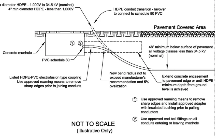
Transition ... 41 Figure B-8. HDPE-to-Manhole Pavement Covered Area Transition ... 42 Figure B-9. HDPE-to-Manhole Pavement Covered Area Transition ... 43
CHAPTER 1 GENERAL 1-1 PURPOSE.
This UFC provides policy and guidance for design criteria and standards for electrical power and distribution systems.
The information provided here must be utilized by electrical engineers in the
development of the plans, specifications, calculations, and Design/Build Request for Proposals (RFP) and must serve as the minimum electrical design requirements. It is applicable to the traditional electrical services customary for Design-Bid-Build
construction contracts and for Design-Build construction contracts. Project conditions may dictate the need for a design that exceeds these minimum requirements.
UFC 3-501-01 provides the governing criteria for electrical systems, explains the delineation between the different electrical-related UFCs, and refers to UFC 3-550-01 for exterior electrical system requirements. Refer to UFC 3-501-01 for design analysis, calculation, and drawing requirements.
Onsite generation is not addressed by this UFC. 1-2 APPLICABILITY.
The design criteria and standards contained within are the minimum requirements acceptable for military installations for efficiency, economy, durability, maintainability, and reliability of electrical power supply and distribution systems. The criteria and standards herein are not intended to be retroactively mandatory.
Comply with the requirements of NFPA 70 and IEEE C2. Generally, IEEE C2 is the basis for UFC 3-550-01 and NFPA 70 is the basis for UFC 3-520-01. However, there are exceptions to which standard applies to each UFC, including:
• Systems covered by other UFCs, such as airfield lighting and shore power systems.
• Exterior circuits such as lighting and service entrance (overhead and underground), which are covered by NFPA 70.
Comply with UFC 3-560-01 for electrical safety requirements applicable to the installation and operation of electrical systems.
Comply with UFC 4-010-01 and UFC 4-020-01 for security requirements related to exterior electrical distribution systems.
Codes and standards are referenced throughout this UFC. The publication date of the code or standard is not routinely included with the document identification throughout the text of the document. In general, the latest issuance of a code or standard has been
assumed for use. Refer to Appendix A to determine the publication date of the codes and standards referenced in this UFC.
\1\
1-3 GENERAL BUILDING REQUIREMENTS.
UFC 1-200-01, "General Building Requirements", provides applicability of model
building codes and government-unique criteria for typical design disciplines and building systems, as well as for accessibility, antiterrorism, security, sustainability, and safety. Use this UFC in addition to UFC 1-200-01 and the UFCs and government criteria referenced therein.
1-4 CRITERIA AND EXEMPTION WAIVER PROCESS.
The criteria and exemption waiver process is provided in MIL-STD 3007. /1/
1-5 REFERENCES.
Appendix A contains a list of references used in this UFC. References applicable to a specific topic are also listed and described in the appropriate sections of this UFC. \1\ /1/
1-6 UTILITY-OWNED AND OPERATED DISTRIBUTION SYSTEMS ON FEDERAL PROPERTY.
This UFC does not apply to:
• Utility-owned and operated distribution systems with right-of-way or easements on Federal property.
CHAPTER 2 ELECTRICAL POWER REQUIREMENTS 2-1 ELECTRICAL POWER REQUIREMENTS: GENERAL.
Virtually all military bases have an existing overhead and underground distribution system that has been in service for many years. As part of any new design project, review the existing design with base personnel to determine which existing features should not be duplicated in future designs. Address design preferences with
responsible engineering and operations personnel as part of the system design analysis.
2-2 SELECTION OF PRIMARY VOLTAGE.
NEMA C84.1 establishes typical voltages and voltage ranges for 60 Hz systems. Facilities located outside of the United States must also comply with the applicable host nation standards; refer to UFC 3-510-01 for additional information.
2-3 DESIGN FOR MAINTENANCE.
Design primary distribution system equipment installations with future periodic
maintenance as a principal consideration. Equipment must be capable of removal from service while minimizing the outage time of affected facilities and missions. Looped and alternate feed designs are essential to allow periodic maintenance.
Provide maintenance criteria with the design analysis as part of the basis for the design as specified in UFC3-501-01.
CHAPTER 3 DESIGN CRITERIA \1\
3-1 MAIN AND ELECTRIC SUPPLY STATIONS/SUBSTATIONS.
All main and electric supply stations/substations shall conform to the requirements of IEEE C2 Part 1, Rules for the Installation and Maintenance of Electric Supply Stations and Equipment, as follows:
• Electric Supply Stations shall be defined as stations that transform the energy level (voltage) for further bulk distribution at medium voltage levels.
• The low voltage equipment in a main or electric supply station (equipment that is being served from a Utilization Electric Supply Station) shall conform to the requirements of NFPA 70.
3-1.1 Main Electric Supply Stations.
The main electric supply station is the installation/utility interface point where further transmission, distribution and utilization of electrical power, the monitoring and control of such power or equipment and the protection of electrical equipment or systems usually becomes the sole responsibility of the Government or their contracted representatives. Coordinate the design of new stations, or modifications to existing stations with the supplying utility and with any other suppliers or users of power supplied through the station.
3-1.2 Utilization Electric Supply Stations.
Utilization Electric Supply Stations are defined as equipment such as pole or pad-mounted transformers or secondary unit substations that transforms the energy level (voltage) to a utilization voltage for consumer use. Some examples of Utilization
Electric Supply Stations are station service transformers (serving low voltage equipment in a Main Electric Supply Station), a lighting transformer (serving equipment for a
roadway lighting system), a pole or pad-mounted transformer (serving a building), or a secondary unit substation (serving piers and wharfs electrical systems).
3-2 GENERAL ELECTRICAL REQUIREMENTS.
Overhead facilities shall conform to the requirements of IEEE C2 Part 2, Safety Rules for the Installation and Maintenance of Overhead Electric Supply and Communication Lines.
Underground facilities shall conform to the requirements of IEEE C2 Part 3, Safety Rules for the Installation and Maintenance of Underground Electric Supply and Communication Lines.
Refer to UFC 3-560-01 Section 1-4.1.1 for arc-flash criteria and the delineation points between IEEE C2 and NFPA 70E conformance requirements.
Design new primary distribution systems as four wire, multi-grounded systems that are wye connected at the source transformer. Provide a system grounded neutral
conductor throughout the system. The neutral shall be bare conductor for overhead systems.
Note: For the Navy, the neutral shall be 600 volt insulated conductor for pole riser and underground systems.
When a project is limited to connecting to an existing three wire system and the primary electrical characteristics are established and defined, continuation of the existing
system shall be permitted with the following requirements:
• For extensions from underground structures, provide a four wire extension. Bond the grounded neutral conductor at each end of the extension to the applicable grounding electrode systems.
• For extensions from overhead pole lines, provide a four wire extension. Bond the grounded neutral conductor at each end of the extension to the applicable
grounding electrode systems.
Note: Design of the extensions as four wire systems does not change any circuit classifications. It provides an extended grounding electrode system to facilitate any future circuit conversions to four wire systems.
Provide equipment foundation pads and ensure a minimum of 10 ft (3 m) clear
workspace in front of pad-mounted equipment for hot stick work. Orient equipment so that adjacent equipment will not interfere with the clear workspace. Provide bollards in areas where equipment is subject to vehicular damage.
Refer to Appendix C for general electrical system criteria. /1/ 3-3 PRIMARY UNIT SUBSTATIONS.
Provide primary unit substations to distribute underground medium voltage circuits. Primary unit substations shall comply with the following industry standards as applicable for the specified configuration:
• IEEE C37.06, AC High-Voltage Circuit Breakers Rated on a Symmetrical Basis – Preferred Ratings and Related Required Capabilities.
• IEEE C37.46, High Voltage Expulsion and Current-Limiting Type Power Class Fuses and Fuse Disconnection Switches.
• IEEE C57.12.28, Pad-Mounted Equipment – Enclosure Integrity.
• IEEE C57.12.00, General Requirements for Liquid-Immersed Distribution, Power, and Regulating Transformers.
• IEEE C57.12.80, Terminology for Power and Distribution Transformers.
• IEEE C57.12.90, Test Code for Liquid-Immersed Distribution, Power, and Regulating Transformers.
• IEEE C57.96, Loading Dry-Type Distribution and Power Transformers.
• IEEE C57.98, Guide for Transformer Impulse Tests.
• IEEE C37.74, IEEE Standard Requirements for Subsurface, Vault, and Padmounted Load- Interrupter Switchgear and Fused Load-Interrupter Switchgear for Alternating Current Systems up to 38 kV.
3-4 SECONDARY UNIT SUBSTATIONS.
Provide secondary unit substations when secondary currents exceed 3,000 amperes. Secondary unit substations shall comply with the following industry standards as applicable for the specified configuration:
• IEEE C57.12.28, Pad-Mounted Equipment – Enclosure Integrity.
• IEEE 57.12.50, Ventilated Dry-Type Distribution Transformers, 1 to 500 kVA, Single-Phase, and 15 to 500 kVA Three-Phase, with High-Voltage 601 to 34,500 Volts, Low-Voltage 120-600 Volts.
• IEEE 57.12.51, Ventilated Dry-Type Power Transformers, 501 kVA and larger, Three-Phase, with High-Voltage 601 to 34,500 Volts, Low-Voltage 208Y/120 to 4160 Volts.
• IEEE C57.12.00, General Requirements for Liquid-Immersed Distribution, Power, and Regulating Transformers.
• IEEE C57.12.01, General Requirements for Dry-Type Distribution and Power Transformers Including Those with Solid-Cast and/or Resin-Encapsulated Windings.
• IEEE C57.12.80, Terminology for Power and Distribution Transformers.
• IEEE C57.12.90, Test Code for Liquid-Immersed Distribution, Power, and Regulating Transformers.
• IEEE C57.12.91, Test Code for Dry-Type Distribution and Power Transformers.
• IEEE C57.96, Loading Dry-Type Distribution and Power Transformers.
• IEEE C57.98, Guide for Transformer Impulse Tests.
• IEEE C57.124, Detection of Partial Discharge and the Measurement of Apparent Charge in Dry-Type Transformers.
3-5 PAD-MOUNTED DISTRIBUTION TRANSFORMERS. 3-5.1 Reference Criteria.
Pad-mounted transformers shall comply with the following industry standards:
• IEEE C57.12.28, Pad-Mounted Equipment – Enclosure Integrity.
• IEEE C57.12.00, General Requirements for Liquid-Immersed Distribution, Power, and Regulating Transformers.
• IEEE C57.12.34, Pad-Mounted, Compartmental-Type, Self-Cooled, Three-Phase Distribution Transformers (2500 kVA and Smaller) – High-Voltage, 34,500 GrdY/19,200 Volts and Below; Low-Voltage: 480 Volts and Below.
• IEEE C57.12.80, Terminology for Power and Distribution Transformers.
• IEEE C57.12.90, Test Code for Liquid-Immersed Distribution, Power, and Regulating Transformers.
• IEEE C57.98, Guide for Transformer Impulse Tests.
• IEEE C57.12.22, Transformers – Pad-Mounted, Compartmental-Type, Self-Cooled, Three-Phase Distribution Transformers with High-Voltage Bushings, 2500 kVA and Smaller: High Voltage, 34,500 Grd Y/19,920 Volts and Below; Low Voltage, 480 Volts and Below.
3-5.2 Configuration.
Use dead-front construction for pad-mounted transformers unless not available within system parameters. Use pad-mounted transformers, separately protected with vacuum fault interrupter equipped switches for 34.5 kV systems.
Do not use pad-mounted transformers with secondary currents exceeding 3,000 amperes because of the size and quantity of secondary conductors. Transformers rated above 1,000 kVA serving 208Y/120 volt loads and above 2,500 kVA serving 480Y/277 volt loads must be in a secondary unit substation configuration.
Minimize double transformations to reduce energy consumption and to minimize items of equipment. Provide two oil-filled pad-mounted transformers in lieu of one 480Y/277 volt service if the required 208Y/120 volt load using dry-type transformers exceeds 40
percent of the 480 volt service transformer capability. Connect equipment at the highest available voltage to minimize the capital cost and energy losses of transformation
equipment.
Three-phase pad-mounted transformers must be loop-feed capable with 6 bushings. Provide two-position, oil-immersed, load break switches that are appropriate for the application. If the transformer might be used as part of a loop-feed design, provide three switches to permit closed transition loop feed and sectionalizing. If the
transformer will be installed at the end of a radial supply with no intention of future loop feed capability, provide a single on-off switch. Provide a spare conduit in the high voltage section extending 5 ft (1.5 m) out from the transformer pad.
3-5.3 Transformer Connections.
Connections shall be delta-wye for three phase systems. 3-5.4 Surge Protection.
Provide bushing-mounted elbow type arresters at the ends of all radials and in normally open locations in loops. Provide arresters for all voltage levels above 5 kV.
3-5.5 Drawing Details.
When using a pad-mounted transformer, select the applicable pad-mounted transformer detail in AutoCAD format from http://www.wbdg.org/ccb/browse_cat.php?o=78&c=232, supply the missing data, and incorporate that detail onto the contract drawings. These details are also provided in a PDF format at
http://www.wbdg.org/ccb/browse_cat.php?o=29&c=248. These drawing details represent typical situations but may not meet all requirements. Modify transformer details as required to indicate the actual requirements for each particular installation. In rare cases when “live front construction” is required due to equipment ratings (available system fault current values), obtain approval from the \1\ Authority Having Jurisdiction (AHJ). /1/ Do not use the pad-mounted transformer details to show secondary unit substations.
3-6 MEDIUM VOLTAGE SWITCHGEAR. 3-6.1 Metal-Clad Switchgear.
Metal-clad switchgear can include either SF6 or vacuum style breakers and must consist of a single section or multiple section line-up of NEMA 1 or NEMA 3R enclosures. Either walk-in or non-walk-in construction can be provided. Medium voltage metal-clad switchgear can be provided as unit substation construction or as stand-alone switchgear. The sections must contain the breakers and the necessary accessory components. The equipment must be factory-assembled (except for necessary shipping splits) and be operationally checked before shipment. Consider remote racking device designs (robots) to rack breakers in and out.
Metal clad switchgear shall comply with the following industry standards:
• IEEE C37.06, AC High-Voltage Circuit Breakers Rated on a Symmetrical Current Basis – Preferred Ratings and Related Required Capabilities.
• IEEE C37.121, Switchgear – Unit Substations Requirements.
• IEEE C37.04, Rating Structure for AC High-Voltage Circuit Breakers Rated on a Symmetrical Current Basis.
• IEEE C37.20.2, Metal-Clad Switchgear.
• IEEE C37.90, Relays and Relay Systems Associated with Electric Power Apparatus.
Provide batteries for dc opening and closing of circuit breakers. Do not use ac or capacitor control methods.
3-6.2 Metal-Enclosed Switchgear.
Do not use metal-enclosed switchgear. Instead, use either a vacuum fault interrupter (VFI) in a unit substation configuration or an upstream pad-mounted switchgear. 3-7 PAD-MOUNTED SWITCHGEAR (SWITCHES).
\1\ For the Navy, utilize multi-way pad-mounted switchgear when switching, isolation, or electrical protection is required. Specify SF6 gas or high fire point liquid
(non-temperature dependent) insulation technology and vacuum bottle interruption
technology. Specify dead front construction with stainless steel tanks and operator full size viewing windows for each switching way. Specify three position (On/Off/Ground) switch ways for all new construction. For switch replacements when existing switching arrangement is On/Off/Tie, a similar arrangement without ground position is permissible. Specify switch design which incorporates operating handles on the opposite side of the tank from the cable entrance bushings, terminations and cables. Specify 600 ampere dead break connectors with 200 ampere interface bushings for each switch way. Air Insulated (fused or non-fused) technology is not permitted. Pad-mount switchgear shall comply with the following industry standards: /1/
• IEEEC57.12.28, Pad-Mounted Equipment – Enclosure Integrity.
• IEEE C37.60, Requirements for Overhead, Pad-Mounted, Dry Vault, and Submersible Automatic Circuit Reclosers and Fault Interrupters for Alternating Current Systems Up to 38 kV.
• IEEE C37.74, IEEE Standard Requirements for Subsurface, Vault, and Padmounted Load- Interrupter Switchgear and Fused Load-Interrupter Switchgear for Alternating Current Systems up to 38 kV.
For the Army and Air Force, \1\ air-insulated and fused switches can be used in either a live-front or dead-front configuration. Do not use air-insulated switches in corrosive /1/and high humidity areas as defined in UFC 3-501-01 unless the installation
experience for the installed location confirms that switch corrosion and tracking is not a problem.
3-8 PAD-MOUNTED SECTIONALIZING TERMINATION CABINETS.
Apply pad-mounted sectionalizing termination cabinets only when switching, isolation, or electrical protection for the downstream circuit is not required or anticipated.
Sectionalizing termination cabinets can be used instead of in-line splices in manholes or for minor loads that do not warrant the expense of pad-mounted switchgear.
Sectionalizing cabinets are available up to 35 kV. Provide low profile sectionalizing termination cabinets when the conductor size is 4/0 awg or smaller.
3-9 CAPACITORS.
Do not use capacitors unless they are needed for power factor correction or to minimize line losses. Verify the need by a system analysis; the analysis must consider the
potential adverse effects of transients caused by capacitor switching. Refer to TSEWG TP-2: Capacitors for Power Factor Correction, at
http://www.wbdg.org/ccb/browse_cat.php?o=29&c=248 for additional information if power factor correction is considered.
Underground distribution has more capacitance than equivalent overhead distribution. When converting from overhead distribution to underground distribution, provide pad-mounted capacitors on a distribution system only if supported by the design analysis. Do not automatically replace existing pole-mounted capacitors with equivalent pad-mounted capacitors.
For safety purposes, include an oil switch disconnect with pole-mounted capacitors. 3-10 OVERHEAD POWER DISTRIBUTION.
\1\ Design overhead lines to IEEE C2 Grade B construction complying with the following:
a. Limit the initial loaded conductor tension to a maximum of 50% of the conductor rated breaking strength. Lesser tensions are usually applicable and generally more preferred. Utility distribution line design is generally in the range of 25% to 35% of the rated breaking strength.
b. Provide clearance requirements using final sag values in conformance with IEEE C2 Part 2.
c. Limit the maximum design tensions for any conductors to 4,750 pounds (2,154 kg). All clearance values shall be based on the following maximum conductor
temperatures.
• Copper phase conductors – 167 degrees F (75 degrees C).
• Aluminum/aluminum alloy phase conductors – 194 degrees F (90 degrees C).
• Neutral conductors for multi-phase circuits – 120 degrees F (49 degrees C).
• The maximum conductor temperature for single-phase neutral conductors shall be identical to the phase conductors.
/1/
Match the existing base construction methods. Match those construction methods used by the local utility when directed. Where new overhead distribution is required, route the overhead distribution along roadways and other major topographical features; the poles must be accessible for future maintenance or work. Coordinate pole locations with land-use planning to ensure that new poles do not interfere with future facility plans. \1\ /1/
Use NAVFAC pole details OH-1.1 through OH-41 whenever applicable. NAVFAC pole details are available in Adobe PDF format and in AutoCAD format
http://www.wbdg.org/ccb/NAVGRAPH/graphtoc.pdf. In situations where an applicable pole detail has not been developed, provide new detail drawings as required. Designer developed details shall contain a level of detail equivalent to NAVFAC pole details and include material requirements. Refer to UFC 3-501-01 for additional pole detail
requirements.
3-10.1 Pole Types.
Use solid wood poles for electric distribution lines; concrete and steel poles can be used for roadway or area lighting circuits carried underground or separately from distribution lines. Concrete or steel poles may be justified for medium-voltage distribution circuits where wood poles do not provide adequate strength, or where climatic conditions cause wood poles to deteriorate rapidly. Do not use laminated wood poles for electric
distribution lines.
3-10.2 Conductors.
\1\ Due to the increasing technology improvements with aluminum conductors and connectors, and the economic disadvantage of providing copper conductors, provide aluminum conductor steel reinforced (ACSR) or aluminum alloys for new overhead lines and extensions of existing lines. Except for grounding systems, the use of copper conductors is prohibited without specific approval and documentation by the applicable local engineering authority. Do not use ACSR conductors in corrosive and high
humidity areas. For corrosive and high humidity areas, provide Type ACSS conductors. For the Navy, the Facilities Engineering Command (FEC) organization’s chief engineer shall have the authority to use copper product for their applicable jurisdiction. Provide
documented correspondence, that supports this decision, to the technical criteria office (NAVFAC LANT CI47) responsible for issuing subject criteria.
For the Army, the Installation Department of Public Works Chief Engineer shall have the authority to use copper product for their applicable jurisdiction if documented in the planning process and the design analysis.
For the Air Force, the Base Civil Engineer shall have the authority to exercise the criteria option of copper product for their applicable jurisdiction if documented in the planning process and the design analysis. /1/
3-10.3 Pole-Mounted Transformers.
\1\ Provide pad-mounted transformers rather than pole-mounted transformers for new three-phase installations larger than 75 kVA.
Use only single phase transformers for pole-mounted installations. For single phase installations and when banking single phase transformers for three phase applications, apply phase-to-neutral primary connections unless installed on three wire distribution systems.
Limit pole-mounted transformer sizes (except for projects involving system conversions to a different operating voltage) as follows:
• Three-phase installations – limited to three 25 kVA transformers or smaller.
• Single-phase installations – limited to one 75 kVA transformer or smaller. Do not use pole-platform mounting (two-pole structure or H-frame). /1/
Do not use self-protected transformers. Self-protected transformers have internal primary fuses that must be replaced by experienced personnel.
Aerially mounted installations might supply several buildings. When that is the case, install the transformers at the pole location closest to the building with the greatest load. Secondary wiring should drop directly to the buildings served, if the span does not
exceed 125 feet; otherwise, intermediate poles are required. 3-10.4 Pole Top Switches.
Pole top switches are installed at important system locations to allow either isolation of the downstream circuit or cross-connection to a different circuit. Where ground
operated, gang type, three phase, air break switches are used with non-insulated
operator handles, provide a metal plate or grate at ground level for the operator to stand on when operating the switch. Connect the metal plate or grate to the pole ground conductor as well as through a braided conductor connection to the switch handle mechanism. Include a provision for locking ground accessible switch handles in the open and closed position.
Single-pole knife blade switches and copper barrels inside distribution cutouts are only acceptable for use in locations where frequent switching is not expected.
3-10.5 Surge Arresters.
Provide surge arresters on the line side of:
• Pole mounted transformers.
• Overhead to underground terminal poles.
• All “normally open” switch ways of pad-mounted sectionalizing switches connected to and served from overhead lines.
• Underground primary metering installations connected to and served from overhead lines.
Provide surge arresters on the line and load sides of:
• Gang operated airbreak switches on overhead lines.
• Primary metering applications on overhead lines.
• Recloser/sectionalizer applications on overhead lines. 3-10.6 Fuse Protection.
Provide IEEE C37.41 rated backup current limiting fuses in series with Type K expulsion fuses on systems that are:
• Greater than 15 kV.
• 15 kV and lower that have available fault currents equal to or greater than 7,000 asymmetrical amperes.
Note: Existing systems should continue to use the expulsion fuse link type that represents the standard for that system.
3-10.7 Automatic Circuit Reclosing.
Do not provide automatic circuit reclosing on underground distribution circuits. 3-10.8 Grounding Connections.
3-11 UNDERGROUND ELECTRICAL SYSTEMS. 3-11.1 Underground Distribution General Criteria. Provide underground distribution as follows:
• In areas where the primary distribution is already underground.
• In locations where overhead distribution is operationally hazardous, such as within airfield clearance zones.
• As required to supply pad-mounted equipment and transformers.
• Near electronics or munitions facilities that have clearance requirements for overhead power lines.
• Near piers and loading areas where overhead cranes operate.
• In congested industrial areas.
• In areas where storm and hurricane damage can damage \1\ /1/overhead distribution.
\1\ Due to the increasing technology improvements with aluminum conductors and connectors and the economic disadvantage of providing copper conductors, provide aluminum conductors for new underground lines and extensions of existing lines. This includes all new medium voltage system designs that do not require interface (splicing copper to aluminum in underground structures) with existing copper infrastructure. Grounding electrode systems shall always be copper.
The use of copper conductors is authorized for extensions of existing systems in which the use of aluminum results in technical limitations, such as:
• Maintaining required circuit ampacity, including derating associated with number of circuits in a common ductbank or burial depth.
• Maintaining base infrastructure capacity, including feeder cross-tie capability.
• Conduit size. All phases are required to be installed in the same conduit.
• Undersized or congested structures necessitating tape splices of aluminum cable to existing copper cable. Note: If adequate space exists for the use of improved technology “heat shrink or cold shrink” splices, or if proper
aluminum to copper compression connectors designed for the natural offset of size difference between the conductor materials is available as a standard manufactured product, provide the copper to aluminum cable extension.
For the Navy, the Facilities Engineering Command (FEC) organization’s chief engineer shall also have the authority to use copper product for applications within their
applicable jurisdiction, in addition to the above authorized use for extensions. In this case, provide documented correspondence, that supports this decision, to the technical criteria office (NAVFAC LANT CI47) responsible for issuing subject criteria.
For the Army, the Installation Department of Public Works Chief Engineer shall also have the authority to use copper product, in addition to the above authorized use for extensions, within their applicable jurisdiction if documented in the planning process and the design analysis.
For the Air Force, the Base Civil Engineer shall also have the authority to exercise the criteria option of copper product, in addition to the above authorized use for extensions, within their applicable jurisdiction if documented in the planning process and the design analysis. /1/
Do not route primary underground utilities under buildings. Systems greater than 600 volts shall also not be routed under buildings except as a direct service entrance to a single interior transformer.
Tag all underground cables in all accessible locations such as in manholes, transformers, switches and switchgear. Install a detectable locator tape above all buried underground circuits. Marking must meet the base utility standards.
3-11.2 Ductbanks.
The definition of the terms ductbank, conduit, and duct are often confused. Within this UFC, a ductbank consists of two or more conduits (or ducts) routed together in a common excavation with or without concrete encasement. Refer to paragraph \1\ 3-11.4 /1/ for criteria applicable to directional boring.
3-11.2.1 Conduit Size.
Minimum conduit sizes must be as follows:
• \1\ Primary Distribution Conduits (along main run between underground structures) – 6 in concrete encased (155 mm).
Note: For the Army and Air Force, this conduit size can be 5 in (127 mm) if the conductor size is 500 kcmil or smaller for 15 kV and below.
Primary Distribution Conduits (on laterals) and Secondary Distribution Conduits – 4 in (103 mm).
Secondary distribution conduits refer to the conduit routing from the
not apply to street lighting circuits, housing service drops, or secondary circuits originating from an interior panel. /1/
• Telecommunication Conduits – 4 in (103 mm). 3-11.2.2 Installation.
• Use Type EB Schedule 20 PVC conduits (minimum thickness) for conduits installed in concrete encasement. Provide at least 3 in (75 mm) of concrete encasement.
• Use Schedule 40 PVC conduit (minimum thickness) for conduits that are not installed in concrete encasement.
• Bury conduit at a minimum depth of 18 in (450 mm) below grade. Conduits must be 24 in (600 mm) minimum depth under roads and pavement, and for voltages between 22 kV and 40 kV. Apply conductor ampacity derating when exceeding the NFPA 70 maximum burial depths.
• Provide 3 in (75 mm) clearance between conduits utilizing interlocking plastic spacers.
• Provide spare conduits such that at least 1/3 of the ductbank contains empty conduits.
• Include pull wires (pull string or pull rope) in all spare ducts.
• Provide a transition from Type EB conduit to Schedule 40 PVC conduit before emerging from underground.
• Use directional boring or jack-and-bore techniques for routing conduit(s)
under existing pavement for roadways, aircraft aprons, runways and taxiways. Directional boring can be used for other locations where excavation can
adversely affect daily operations.
Note: Comply with Appendix B for the use of directional boring for conduit installations.
• For permafrost locations, use ductbank installation methods that are the standard for the base, post, or local utility.
3-11.3 Direct Buried Wiring Methods.
The term direct buried wiring refers to the direct burial of conductors without any conduit or concrete encasement. \1\
3-11.3.1 Army and Air Force Criteria.
Direct buried wiring for medium voltage systems is not allowed.
Direct buried wiring for low voltage systems from the distribution transformer to the facility service entrance is not allowed.
Direct buried wiring for low voltage systems is acceptable in large open areas only, such as ranges or outlying training areas.
Sleeve all direct buried conductors under existing roads, paved areas and railroad tracks. Use galvanized rigid steel conduit.
Sleeve all direct buried conductors under new roads and use concrete encased
conduits extending 5 ft (1.5 m) beyond the edge of the pavement. Use galvanized rigid steel or minimum Schedule 40 PVC conduit.
3-11.3.2 Navy Criteria.
Direct buried wiring methods for low or medium voltage systems may be allowed for certain applications. as follows: All applications must be submitted by the using the criteria and exemption waiver process (Paragraph 1-4) and supported with the required documented justification during the planning process of subject design project. Any application which constitutes a part of the facility core distribution infrastructure will not be authorized.
All direct burial systems shall meet ANSI C2 requirements for multi-grounded systems and shall be energized at a maximum nominal system voltage of 34.5 kV.
All approved direct burial medium voltage systems shall be allowed to utilize standard concentric neutral cable design instead of the typical power cable design utilizing a separate 600 insulated volt neutral conductor.
Direct buried systems shall also provide a spare conduit system with associated
enclosures under all streets, roads, and parking areas to provide for future maintenance capability without having to disrupt pavements. Provide minimum Schedule 40 PVC extending 5 feet on each side and capped for future use.
For crossing existing paved areas, the direct boring (DB) technology referenced in Section 3-11.4 shall apply for installation of the direct buried system.
The following are examples of applications that merit consideration:
• Installations for special applications in remote or extremely controlled areas. Examples of such applications could be ranges or range facilities, renewable energy projects such as wind farms or bulk photovoltaic (PV) facilities provided for the purpose of supplementing system demand loading .
• Housing projects utilizing residential type distribution principles of single-phase, pad-mounted transformer designs and single-phase distribution principles for balanced three phase system loading.
• Bulk power transfer (feeder) from point to point crossing remote or controlled real estate which will revert to public utility ownership and maintenance upon
completion. /1/
3-11.4 Directional Boring.
Directional boring (DB) is a trenchless technology method to install high density polyethylene electrical (HDPE) conduit used for underground electrical distribution systems.
3-11.4.1 Authorized Locations.
DB methods shall not be chosen as an installation means in lieu of concrete encasement or other approved jack-and-sleeve techniques, based solely on cost. Concrete encasement and jack-and-sleeve techniques always provide the best means to protect conduit and conductors; therefore, DB is authorized only for crossing under the following:
• Roads.
• Parking lots.
• Airfield aprons, taxiways, or runways (not airfield lighting circuits).
• Bodies of water.
• Environmentally sensitive areas with appropriate federal, state, and local government approval.
• Historical preservation areas with appropriate federal, state, and local government approval.
3-11.4.2 Limitations.
DB is applicable to medium-voltage (HV) underground distribution systems between 1000 volts (V) and 34.5 kilovolts (kV) (nominal) and all low-voltage distribution systems (less than 1000 V). It is not applicable to airfield lighting circuits.
Use of DB techniques to install electrical conduit distribution for voltages greater than 34.5 kV (nominal) is prohibited.
Refer to Appendix B regarding depth of DB. The depth can be less if a detailed survey is performed and documented before starting boring.
3-11.5 Underground Structures (Manholes and Handholes). Provide separate power and communication manholes. When power and
communication duct lines follow the same route, use a common trench and locate power and communication manholes in close proximity to one another and staggered. Use manholes for main duct runs and wherever shielded medium voltage cable is installed. For the Air Force, pad-mounted sectionalizing termination cabinets can be used instead of manholes for locations that do not have multiple feeders.
Handholes can only be used for airfield lighting circuits, for other non-shielded medium voltage circuits, and for low-voltage and communication lines.
All in-line splices must be in underground structures. Do not use handholes for splicing shielded power cables.
The following equipment is prohibited inside underground structures:
• Load junctions.
• Separable splices (bolt-T connections).
• T-splices and Y-splices on systems rated for greater than 15 kV.
• For the Air Force, T-splices and Y-splices on medium voltage systems rated for less than 15 kV.
• Power distribution equipment, including transformers and switches. Individually fireproof medium voltage cables in all underground structures.
Specify H20 highway loading for most locations. Structures subject to aircraft loading must be indicated to the Contractor. Design decks and covers subject to aircraft loadings per FAA AC-150/5320-6D except as follows:
• Design covers for 100,000 lb (45,000 kg) wheel loads with 250 psi (1.72 MPa) tire pressure.
• For spans of less than 2 ft (0.6 m) in the least direction, use a uniform live load of 325 psi (2.24 MPa).
• For spans of 2 ft (0.6 m) or greater in the least direction, the design must be based on the number of wheels which will fit the span. Use wheel loads of 75,000 lb (34,000 kg) each.
Note: For the Air Force, do not install electrical manholes in aprons. Maintain a distance of 50 ft (15 m) from the edge of paving, 50 ft (15 m) from any hydrant lateral control pit, and 200 ft (60 m) from a fueling point for all manholes.
Determine the size of power manholes by the number of circuits, voltage ratings and splicing requirements of the cables within. Manholes shall be a minimum 2 m (6.5 ft) deep. Provide cable racks in all new manholes. When reworking cables in existing manholes, provide racks for new cables. Route cable installations inside manholes along those walls providing the longest route and the maximum spare cable lengths. For circuits rated above 15 kV, manholes shall be a minimum of 9 ft by 12 ft (2.8 m by 3.7 m) in interior size.
Size communications manholes for equipment and splices contained, including future projections. Manholes must accommodate racking of splice closure of largest multi-pair cable while keeping cable bending radii greater than 10 times cable diameter.
Provide manhole foldout details or exploded views for all multiple-circuit primary
systems and all primary systems requiring splices. Indicate the entrance of all conduits and the routing of all conductors in the manholes. Manhole details are available in Adobe PDF format at http://www.wbdg.org/ccb/NAVGRAPH/graphtoc.pdf and in AutoCAD format at http://www.wbdg.org/ccb/browse_cat.php?o=78&c=232. 3-11.6 Locating Underground Structures.
Provide where splices are required, where duct lines change direction, and within 100 ft (30 m) of every riser pole, pad mounted transformer, or unit substation unless a
calculation is provided to justify a greater distance. The distance must not exceed 200 ft (60 m).
Separation on straight runs must not exceed 400 ft (120 m). In situations where greater separation is desired and this greater separation is not prohibited by either excessive pulling tension or site requirements, separation of up to 600 ft (180 m) is permitted. 3-11.7 Pull Boxes.
Pull boxes are used for electric circuits supplying low-voltage electric loads which require conductors no larger than 1/0 awg and no more than one 2-inch (52 mm)
conduit entrance at each side. Wherever larger conduits are installed, use handholes or manholes. Do not use pull boxes in areas subject to vehicular traffic.
3-11.8 Medium Voltage Cable.
\1\ Medium voltage cables shall comply with NEMA WC 74, be type MV (105°C) aluminum or copper based on the specific applications as defined in Para. 3-11.1, and shall contain a 600 volt insulated neutral when required. For the Army and Air Force, concentric neutral conductors are also authorized.
Cables shall meet the following criteria:
• Insulation Type – Provide ethylene propylene rubber (EPR). For the Army and Air Force, cross-linked polyethylene is also authorized. Do not use paper insulated lead covered (PILC) for new installations.
• Insulation Level – The insulation level for all circuits classified as multi-grounded (4 wire systems throughout the entire circuit) shall be 100%
minimum. Insulation level for all other classification of circuits shall be 133%.
• Cable Shields – Use copper-tape shielded cables and ensure minimum bending radii of 12 times the overall cable diameter. Use copper-wire shielded cables only where existing manholes are utilized and the minimum cable bending radii of tape shielded cables cannot be realized. Refer to NEMA WC 74 for cable bending radii. /1/
• Number of Conductors – Use single conductor cable as a general rule. Three conductor cable may be used only when splicing to existing three conductor cable.
3-12 CONCRETE FOR UNDERGROUND ELECTRICAL SYSTEMS.
Concrete for encasement of underground ducts must be 3000 psi (20 MPa), minimum 28-day compressive strength. Concrete associated with electrical work for other than encasement of underground ducts must be 4000 psi (30 MPa), minimum 28-day compressive strength unless specified otherwise.
3-13 HOUSING DISTRIBUTION.
The following requirements shall be met for electrical distribution to housing units:
• Serve single dwelling units, duplexes and quadra-plexes in housing areas by single-phase, 240/120V transformers.
• Serve no more than 6 dwelling units; 4 duplexes; or 2 quadraplexes per transformer.
• Minimum conductor size from the transformer to the service entrance equipment should be 3/0 copper in underground conduit.
• Maximum length of service lateral conductors from the distribution
transformer to the service entrance device (or meter base) shall be 220 ft (67 m).
• Design the distribution system such that the available fault current at the service equipment is less than 10,000 amperes.
Where an underground 3-phase circuit is used to feed single-phase transformers, provide a separate 3-phase pad-mounted switch or sectionalizing cabinet with a radial supply to the single-phase transformers.
3-14 DISTRIBUTION SYSTEM GROUNDING.
\1\ Distribution system grounding (medium voltage systems classified as
multi-grounded, single point grounded at source transformer either solidly or with grounding resistors, and ungrounded) shall comply with the requirements of IEEE C2 Section 9 entitled Grounding Methods for Electric Supply and Communication Facilities.
3-14.1 Main Electric Supply Station
Main electric supply stations and all supply stations consisting of equipment for the purpose of transforming the voltage level for further bulk distribution shall be designed in conformance with IEEE Standard 80. The station grounding system shall require measurement prior to inter-connection with other systems and prior to station
energization to assure the limits of step and touch potentials as required by IEEE Standard 80 have been attained.
3-14.2 Utilization Electric Supply Station
A Utilization Electric Supply Station is defined as any station where the medium voltage system transforms the energy level (voltage) to utilization for consumer use on any kind of facility. Examples of some utilization electric supply stations are roadway lighting transformers, a building pad-mounted transformer, or a pier or wharf secondary unit substation.
3-14.3 Separation of Grounding Conductors
The requirement for separation of grounding conductors between classes of equipment operating in excess of 750 volts and below 750 volts shall be complied with for the design for all facilities. The exception for connecting the different classes of equipment “to a sufficiently heavy ground bus or system ground cable that is well connected to ground at more than one place” is the Government’s engineering basis for
interconnecting the different classes of equipment connected to existing systems. Note: The predominant classification of existing Government medium voltage systems is a classification of something other than multi-grounded. For designs on new systems or existing systems classified as multi-grounded, the standard grounding detail of a 4/0 ground ring and interconnecting ground rods on utilization electric supply stations may be omitted and replaced with a simpler system complying with the requirements of IEEE C2 Section 9.
3-14.4 Materials and Special Requirements 3-14.4.1 Ground Rods.
Ground rod composition, minimum spacing requirements and connections shall conform to requirements of IEEE C2 Section 9 except that minimum dimensions shall be 10 ft (3.0 m) in length and ¾ inch (19 mm) in diameter. Ground rods shall be copper-clad steel, solid copper, or stainless steel. Sectional ground rods are permitted.
All connections to ground rods below ground level must be by exothermic weld connection or with a high compression connection using a hydraulic or electric compression tool to provide the correct circumferential pressure. Accessible
connections above ground level and in test wells can be accomplished by clamping. Spacing for driving additional grounds must be a minimum of 10 ft (3.0 m). Bond these driven electrodes together with a minimum of 4 AWG soft drawn bare copper wire buried to a depth of at least 12 in (300 mm).
Pole–butt plates and wire wraps recognized by IEEE C2 Section 9 shall not be recognized as grounding electrodes.
3-14.4.2 Ground Rings.
Ground rings shall conform to the requirements of NFPA 70 Section 250.
If the system is not classified as multi-grounded, utilization electric supply stations, switchgear, and sectionalizing cabinets require a 4/0 bare copper ground ring with a minimum of four ground rods for three phase service. Single phase service installations can be modified to minimum 1/0 copper and two ground rods for the ground ring. Test wells are permitted on specific applications as required.
If metal bollards are installed and are within 8 feet of the pad-mounted equipment, bond each bollard to the ground ring.
3-14.5 Low Voltage Grounding Interface With Utilization Electric Supply Stations
For design purposes, the secondary terminals of the utilization electric supply station shall be the demarcation point between IEEE C2 and NFPA 70. The transition between the grounded neutral conductor (functioning as a neutral and a grounding conductor per IEEE C2) and the grounded conductor (functioning as a neutral conductor only per NFPA 70) shall be at the “service point” as defined by UFC 3-501-01 Chapter 2.
• The service point for low-voltage conductors from utilization electric supply stations containing no secondary overcurrent protection device shall be defined as the line side terminals for the facility service equipment.
• The service point for utilization electric supply stations containing an
overcurrent protection device shall be at the main breaker on the secondary side of the utilization electric supply station. This is the transition point from IEEE C2 to NFPA 70 grounding where the service main bonding jumper is located.
3-14.6 Grounding Requirements – Fences
Metal fences for electrical equipment and ordnance facilities shall be grounded in accordance with IEEE C2 Section 9.
Other metal fences that are electrically continuous with metal posts extending at least 24 inches (610 mm) into the ground require no additional grounding unless specifically required by other criteria.
For Army and Air Force, ground all metal fences at or near points crossed by overhead power lines in excess of 600 volts and also at distances of 150 ft (46 m) on each side of the line crossing.
Where plastic coated fabric is used, remove plastic coating where it overlaps the post to be grounded and braze or bolt conductor to post.
/1/
3-15 METERING.
Supply housing units with meter sockets only. Sockets must be single phase, four terminal, and ring-less with manual bypass device and polycarbonate blank cover plate. For all other services, provide electronic programmable watt-hour meters with solid-state demand registers. Include necessary KYZ initiation hardware for Energy Management and Control System (EMCS) coordinated with the mechanical Direct Digital Control System (DDC). Locate watt-hour meters directly on pad mounted transformers or integral to unit substations.
3-16 EXTERIOR SITE LIGHTING.
Provide exterior lighting in accordance with UFC 3-530-01. 3-17 CATHODIC PROTECTION SYSTEMS.
Provide cathodic protection in accordance with UFC 3-570-02N for the Navy and UFC 3-570-02A for the Army.
3-18 ENVIRONMENTAL CONSIDERATIONS.
Consider oil spill containment for substation transformers. Containment is not authorized for pad-mounted oil-filled distribution transformers and switches.
Do not use askarel-insulated and nonflammable, fluid-insulated transformers because of environmental concerns as to their insulation liquid.
3-19 FIRE PROTECTION CONSIDERATIONS.
Provide fire protection and specify installation location for oil-filled equipment in accordance with UFC 3-600-01.
Oil-filled transformers using mineral oil can only be used outdoors. Less-flammable liquid transformers may be used either outdoors or indoors; these liquids shall have a fire point of not less than 300 degrees C (575 degrees F).
GLOSSARY Acronyms and Abbreviations
AC Alternating Current
ACSR Aluminum Conductor Steel-Reinforced \1\ACSS Aluminum Conductor Steel Supported /1/ A/E Architect/Engineer
AFCESA Air Force Civil Engineer Support Agency AHJ Authority Having Jurisdiction
AL Aluminum
ASTM American Society for Testing and Materials AWG American Wire Gauge
UFC Unified Facilities Criteria BCE Base Civil Engineer BIL Basic Insulation Level CT Current Transformer
CU Copper
DB Directional Boring DDC Direct Digital Control
DIA Diameter
DoD Department of Defense
EMCS Energy Management and Control System \1\ ESS Electric Supply Station /1/
Degrees F Degrees Fahrenheit
fc Footcandles
ft Feet (or Foot) ft2 Foot Squared
GPS Global Positioning System
HDPE High Density Polyethylene Electrical
HQUSACE Headquarters, US Army Corps of Engineers HV High Voltage
HVAC Heating Ventilation and Air Conditioning
Hz Hertz
IEEE formerly Institute of Electrical and Electronic Engineers
in Inch
kcmil Thousand circular mils
kg Kilograms kV Kilovolts kVA Kilo-Volt-Ampere kVAR Kilo-Volt-Ampere-Reactive lb Pound LTC Load-Tap Changing m Meter m2 Meter Squared Max Maximum Min Minimum
mm Millimeter MPa Mega-Pascals
MTS Maintenance Testing Specifications MVA Mega-Volt-Ampere
NAVFAC Naval Facilities Engineering Command NEC National Electrical Code
NEMA National Electrical Manufacturers Association NETA InterNational Electrical Testing Association NFPA National Fire Protection Association
OH Overhead
O&M Operation and Maintenance PE Professional Engineer psi Pounds per square inch
PILC Paper Insulated Lead Covered PPE Personal Protective Clothing PT Potential Transformer
PVC Polyvinyl Chloride RFP Request for Proposal
SCADA System Control and Data Acquisition SF6 Sodium Hexafluoride
TSEWG Tri-Service Electrical Working Group \1\ UESS Utilization Electric Supply Station /1/ UL Underwriters Laboratories
UFC Unified Facilities Criteria
V Volt
VA Volt-Amp
VFI Vacuum Fault Interrupter W/ft2 Watts per Foot Squared W/m2 Watts per Meter Squared Terms
Activity – The end user of a facility. \1\
Contractor – Person(s) doing actual construction portion of a project.
Corrosive Area – An area identified by the Technical Reviewing Authority as requiring special equipment corrosion mitigation methods.
/1/
Designer of Record – The engineer responsible for the actual preparation of the construction documents.
\1\
Electric Supply Station – A station that transforms the energy level (voltage) for further bulk distribution at medium voltage levels.
Facility Core Distribution Infrastructure – System components that constitute a part of the base infrastructure system that are required to provide electrical service to multiple users.
/1/
Low Voltage System – An electrical system having a maximum root-mean-square (rms) voltage of less than 1,000 volts.
Medium Voltage System – An electrical system having a maximum RMS ac voltage of 1,000 volts to 34.5 kV. Some documents such as NEMA C84.1 define the medium voltage upper limit as 100 kV, but this definition is inappropriate for facility applications. Project Manager – Engineer charged with the administration of the project.
Service – The conductors and equipment for delivering electrical energy from the serving utility or Government-owned system to the wiring system of the premises served.
Site Electrical Utilities – Site Electrical Utilities are the primary electric power
distribution to the facilities and other electrical loads, all exterior lighting not attached to the building; and all telecommunication services (fiber optic, copper cable, CATV, etc.) required by the Facilities.
\1\
Utilization Electric Supply Station – Equipment such as pole or pad-mounted
transformers or secondary unit substations that transforms the energy level (voltage) to a utilization voltage for consumer use.
APPENDIX A REFERENCES
Note: The most recent edition of referenced publications applies, unless otherwise specified. 1
Military Publications
\1\ UFC 3-260-01, Airfield and Heliport Planning and Design. /1/ UFC3-501-01,Electrical Engineering.
UFC 3-510-01, Foreign Voltages and Frequencies Guide.
UFC 3-530-01, Design: Interior and Exterior Lighting and Controls. UFC 3-560-01, Electrical Safety, O&M.
UFC 3-570-02A, Cathodic Protection.
UFC 3-570-02N, Electrical Engineering Cathodic Protection.
\1\ UFC 3-575-01, Lightning and Static Electricity Protection Systems. /1/ UFC 3-600-01, Fire Protection Engineering for Facilities.
UFC 4-010-01, DoD Minimum Anti-Terrorism Standards for Buildings. UFC 4-020-01, DoD Security Engineering Facilities Planning Manual.
\1\ UFC 4-211-01N, Aircraft Maintenance Hangars: Type I, Type II and Type III. UFC 4-211-02NF, Corrosion Control and Paint Finishing Hangars. /1/
IEEE (formerly Institute of Electrical and Electronics Engineers) IEEE C2, National Electrical Safety Code.
IEEE C37.04, Rating Structure for AC High-Voltage Circuit Breakers Rated on a Symmetrical Current Basis.
IEEE C37.06, AC High-Voltage Circuit Breakers Rated on a Symmetrical Current Basis – Preferred Ratings and Related Required Capabilities.
IEEE C37.20.2, Metal-Clad Switchgear.
IEEE C37.41, Design Tests for High-Voltage Fuses, Distribution Enclosed Single-Pole Air Switches, Fuse Disconnecting Switches, and Accessories.
IEEE C37.46, High Voltage Expulsion and Current-Limiting Type Power Class Fuses and Fuse Disconnection Switches.
IEEE C37.60, Requirements for Overhead, Pad-Mounted, Dry Vault, and Submersible Automatic Circuit Reclosers and Fault Interrupters for Alternating Current Systems Up to 38 kV.
IEEE C37.74, IEEE Standard Requirements for Subsurface, Vault, and Padmounted Load- Interrupter Switchgear and Fused Load-Interrupter Switchgear for Alternating Current Systems up to 38 kV.
IEEE C37.90, Relays and Relay Systems Associated with Electric Power Apparatus.
1
Addresses for standards:
1. Institute of Electrical and Electronics Engineers, 3 Park Avenue, 17th Floor, New York, NY 10016 2. International Electrical Testing Association, 3050 Old Centre Ave., Suite 102 Portage, MI 49024 3. National Electrical Manufacturers’ Association, 1300 North 17th Street, Suite 1752, Rosslyn, VA
22209National Fire Protection Association, One Batterymarch Park, P.O. Box 9101, Quincy, MA 02269.
IEEE C37.121, Switchgear – Unit Substations Requirements.
IEEE C57.12.00, General Requirements for Liquid-Immersed Distribution, Power, and Regulating Transformers.
IEEE C57.12.01, General Requirements for Dry-Type Distribution and Power
Transformers Including Those with Solid-Cast and/or Resin-Encapsulated Windings. IEEE C57.12.22, Transformers – Pad-Mounted, Compartmental-Type, Self-Cooled,
Three-Phase Distribution Transformers with High-Voltage Bushings, 2500 kVA and Smaller: High Voltage, 34,500 Grd Y/19,920 Volts and Below; Low Voltage, 480 Volts and Below.
IEEE C57.12.28, Pad-Mounted Equipment – Enclosure Integrity.
IEEE C57.12.34, Pad-Mounted, Compartmental-Type, Self-Cooled, Three-Phase Distribution Transformers (2500 kVA and Smaller) – High-Voltage, 34,500 GrdY/19,200 Volts and Below; Low-Voltage: 480 Volts and Below.
IEEE C57.12.50, Ventilated Dry-Type Distribution Transformers, 1 to 500 kVA, Single-Phase, and 15 to 500 kVA Three-Single-Phase, with High-Voltage 601 to 34,500 Volts, Low-Voltage 120-600 Volts.
IEEE C57.12.51, Ventilated Dry-Type Power Transformers, 501 kVA and larger, Three-Phase, with High-Voltage 601 to 34,500 Volts, Low-Voltage 208Y/120 to 4160 Volts. IEEE C57.12.80, Terminology for Power and Distribution Transformers.
IEEE C57.12.90, Test Code for Liquid-Immersed Distribution, Power, and Regulating Transformers.
IEEE C57.12.91, Test Code for Dry-Type Distribution and Power Transformers. IEEE C57.96, Loading Dry-Type Distribution and Power Transformers.
IEEE C57.98, Guide for Transformer Impulse Tests.
IEEE C57.124, Detection of Partial Discharge and the Measurement of Apparent Charge in Dry-Type Transformers.
IEEE 80, IEEE Guide for Safety in AC Substation Grounding. National Fire Protection Association
NFPA 70, National Electrical Code.
NFPA 70B, Electrical Equipment Maintenance.
\1\ NFPA 70E-2012, Standard for Electrical Safety in the Workplace. The 2012 edition has been published and is under review by the Tri-Services Electrical Working Group. Additional applicable changes in the 2012 edition will be incorporated into criteria in the next revision. /1/
National Electrical Manufacturers’ Association
NEMA C84.1, Electric Power Systems and Equipment-Voltage Ratings (60 Hz). Miscellaneous Documents
ASTM D2447, Standard Specification for Polyethylene (PE) Plastic Pipe, Schedules 40 and 80, Based on Outside Diameter.
IEEE C57.12.22, Transformers – Pad-Mounted, Compartmental-Type, Self-Cooled, Three-Phase Distribution Transformers with High-Voltage Bushing, 2500 kVA and Smaller: High Voltage, 34,500 Grd Y/19,920 Volts and Below; Low Voltage, 480 Volts and Below.
NEMA WC 74, 5-46 KV Shielded Power Cable for Use in the Transmission and Distribution of Electric Energy.
NEMA TC7, Smooth-Wall Coilable Polyethylene Electrical Plastic Conduit. NETA MTS, Maintenance Testing Specifications.