D
rainage of rainwater has long been considered an essential attribute for the proper performance of any roof system. Long-term and excessive accumulation of water will contribute to the deterioration of most roofing systems and, in worst-case scenarios, has been responsible for exces sive live loads that can lead to structural collapse.Roofing systems commonly rely upon roof drains and through-wall scuppers for drainage. The effects of debris on the flow rate characteristics of roof drains and scup pers has not been well understood or stud ied.
Routine maintenance, which should include intermittent cleaning of debris from roof surfaces, has always been recommend ed within the roofing industry. An August 2009 article by Eddie Garcia in Western Roofing Magazine discusses the importance of roof maintenance and specifically the importance of keeping a roof free of debris.1 Numerous other authors, including Griffin and Fricklas,2 also address the importance of roof drainage and maintenance.
The reality, however, is that roof main tenance usually occurs only after a leak or
roof problem develops. The failure to rou tinely clean a roof can and has led to serious roof problems. Proper roof maintenance is the ultimate responsibility of the building owner.
This article reviews the effects of roof type and debris on the flow rate characteris tics of roof drains and scuppers. This study was limited to debris accumulation on roof surfaces and does not consider the effects of debris within drainpipe leader systems. The data generated assume that drain leaders are clear and free to flow.
BaCKgROuND
Drainage of roofing systems has typ ically been accomplished by a combina tion of slope, perimeter gutters, internal roof drains, and/or through-wall scuppers. Proper roof drainage has long been required by national building codes. Within the roofing industry, organizations such as the National Roofing Contractors Association (NRCA) and manufacturers have made long-standing recommendations and require ments for proper roof drainage.
Most roofing material manufacturers require a positive slope and that a new roof will drain and be free of ponding water within 48 hours after a rainfall event. A few
single-ply and old coal-tar manufacturers have permitted accumulation of water on their roofing systems.
INTeRNaTIONal BuIlDINg/ PlumBINg CODe
By law, roof construction has to be in compliance with locally adopted build ing codes. The International Building Code (IBC)3 is currently the most uniformly accepted code within the United States. The IBC requires positive slope for new con struction and incorporates the International Plumbing Code (IPC),4 which addresses requirements for roof drainage.
The required minimum size for roof drains and/or scuppers for a given roof area is dependent upon a number of factors, including the following:
• Geographic location
• 100-year one-hour rainfall rate • Below-deck drainpipe system (verti
cal or sloped)
PRImaRy DRaIN eXamPle
Orlando, Florida, falls within an area of the IPC, per Figure 1106.1, that indicates the maximum anticipated 100-year rainfall event could be up to 4.5 in. of rain per hour. The determination of the size of a roof drain
scupper system can accommodate the anticipated rainfall event.
The flow rate for a given condition in gallons per minute (gpm) can be calculated. For the Orlando roof with 6,795 sq. ft. that experiences a 4.5-in. rainfall in one hour, the roof drain system should be capable of with standing flow rates of up to 317 gpm during a maximum rainfall event (Table B). ROOf DRaIN STRaINeR
The IPC, in Section 1105.1, Strainers, also requires that roof drains have strainers with inlet openings equal to 150% of the cross-sectional area for a given drain pipe. As an example, for a 6-in. roof drain, the given cross-sectional area is approximately 28.3 sq. in. The strainer for a 6-in. roof drain would be required to have an inlet opening of at least 42.4 sq. in. The IPC does not distinguish between the vertical inlet open areas or horizontal sections on the top of the strainer. (See Photo 1.)
SeCONDaRy DRaINage
Under Section 1107 of the IPC, second
ary roof drains are required in addition to the primary drainage system. Secondary drainage systems are required for emer gency purposes in the event the primary drainage systems become blocked. The IPC requires that the secondary drainage system have separate points of discharge that are to be sized based on the same rainfall rates as that of the primary drainage system.
If scuppers are used, the size must be sufficient to prevent ponding to a depth that exceeds the design limits of the roof. The exact methodology for determining the sizing of scuppers used as the secondary drainage system is not specified under cur rent requirements of the IPC.
DeBRIS
The type of debris found on a roof sur face varies widely. Typical debris includes vegetation, leaves, trash, cans, bottles, plas tic bags, dirt, etc. Field experience has shown that debris will accumulate starting at the roof surface and will extend upwards along the sides of strainers or scuppers (Photo 2). Debris generated by some of the new “green” roofs may also be problematic. laBORaTORy TeSTINg
In order to evaluate the effects of debris on the performance of roof drains and scup pers, an elevated steel tank was construct ed and connected to pumps and a water reservoir. Different types of drain devices were flooded at incremental flow rates of 200, 400, 600, and 800 gpm. As water was pumped at different flow rates, the depth of water accumulation was measured.
The 6-in. and 8-in. diameter roof drains and four through-wall scupper assemblies were tested under varying conditions.
Properties of Water
1 cubic ft. of water = 62.42 pounds
1 cubic ft. of water = 7.48 gallons
1 gallon of water = 8.34 pounds
Table A
for a given roof area is dependent on the orientation of the below-deck drain piping. Assuming horizontal leader piping at ¼ in. per ft. of slope (Table 1106.3), the maximum area of drainage for a 6-in.-diameter drain would be 6,795 sq. ft. This square footage is based upon an extrapolation between the 4- and 5-in. rainfall rate. The properties of water are included in Table A.
The IPC also requires the installation of independent, separate-but-equal, primary, and secondary drainage systems. The pri mary and secondary systems are to be equal in cross-sectional drainage capacity and have independent discharge piping or lead ers. The theory is that if the primary drain/ scupper becomes blocked for whatever rea son, the secondary independent drain/
6,795 sq. ft. of roof X 4.5-in. rainfall/hr. = 2,548 cubic ft. of water/hr.
2,548 cubic ft. X 7.48 gallons/cubic ft. = 19,059 gallons/hr.
19,059 gallons/hr. = 317 gallons/min.
Table B
Photo 1 – Roof drain strainer.
Photo 2 – Debris at roof drain.
Photo 3 – Simulated debris.
SImulaTeD DeBRIS Simulated debris was placed over the vertical inlets of roof strainers (Photo 3). The vertical inlet strainer openings were restricted at rates of 25%, 50%, and 75%. The resultant accumulation of water, depth, and flow rate were measured. Data generated from this testing are included in Table C.
Testing verified that a relatively small amount of debris would substantially reduce the flow rate capa bilities of a primary drain assembly. As a result, water will accumulate and lead to increased structural loading. As an example, if the 6-in. roof drain installed in Orlando without a second ary drainage system is par tially obscured up to 25%, 50%, or 75%, water depth at the drain will increase
from 4.4 inches to 5.4, 6.3, and 9.8 inches, respectively. As the depth of water increas es, the secondary roof drainage system will engage to prevent excessive structural load ing and potential collapse.
ReTROfIT ROOf DRaINS
Within the single-ply community, a common method of reroofing involves the use of “retrofit roof drains.” The new retro fit roof drains are inserted within existing roof drains. The insert consists of a metal tube or drain stem with a horizontal flange
DRaIN flOW ReSeaRCH
that is welded to the single-ply membrane (Photo 4).
A gasket or backflow seal device placed within the vertical section of the stem expands, forcing the retrofit roof drain and the existing drainpipe to form a watertight seal. A performance standard to test this
laboratory Roof Drain flow Testing; Water level, Height in Inches
8-in. Drain, 14-in. Strainer Dome, 15 ft., 6 in. of 8-in. Drain/PVC Pipe – Horizontal Configuration
Condition – approx. flow rate, gpm Open area, in.2 100 200 300 400 500 600 700 800
Without strainer 48.7 1.7 2.3 2.5 2.7 2.8 3.1 3.4 3.5
With clear strainer 97.0 2.6 2.8 3.4 3.9 4.3 4.7 5.0 5.3
Debris, 25% of side opening 78.8 3.6 3.8 4.4 4.8 5.2 5.5 6.0 6.4
Debris, 50% of side opening 60.6 4.6 4.8 5.2 5.6 6.3 6.6 6.9 7.1
Debris, 75% of side opening 42.4 5.3 5.4 6.0 6.4 6.9 7.3 7.8 7.8
6-in. Drain, 9½-in. Strainer Dome, 15 ft., 6 in. of 6-in. Drain/PVC Pipe – Horizontal Configuration
Condition – approx. flow rate, gpm Open area, in.2 100 200 300 400 500 600 700 800
Without strainer 28.3 2.6 3.3 4.4 5.9 7.5 9.5 12.0 14.8
With clear strainer 51.0 2.6 3.3 4.4 5.9 7.5 9.7 12.8 16.8
Debris, 25% of side opening 40.3 4.9 4.9 5.4 6.3 7.7 9.8 12.4 >18
Debris, 50% of side opening 29.5 5.7 6.0 6.3 7.0 9.3 13.9 >18 >18
Debris, 75% of side opening 18.7 6.4 7.5 9.8 10.3 12.0 >18 >18 >18
eter (area) of the existing drain pipe is reduced. Manufacturers have not ana lyzed the effect the retrofit roof drains have on the reduction of flow rates and/ or increased water accumu lation.
A 6-in. roof drain was ret rofitted with a typical drain insert. The new assembly was then flooded with water. Data seal has been developed by the American generated from the testing of the retrofit roof National Standard Institute (ANSI) and the drains are included in Table D. A compari Single-Ply Roofing Institute (SPRI).5 son of the 6-in. drain with and without the
The net result of installing a retrofit insert is shown in Figure 1. roof drain is that the cross-sectional
diam-DRaIN flOW ReSeaRCH
Photo 4 – Retrofit drain.
ICe DeBRIS
Common debris that accumulates on a roof can be addressed by roof maintenance. In some instances, a hail or snow event can create an accumulation of ice at a roof drain and/or scupper. The accumulation of hail, ice, or snow, in effect, becomes meteorolog ically supplied debris.
During some hail events, a roof drain/ scupper can rapidly become obscured, resulting in an ice dam at the drain/scup per assembly. Water accumulates, backs up, and can produce leakage at roof defects. In worst-case scenarios, water accumula tion can result in roof collapse.
Testing the 6-in. roof drain, 240 pounds of ice was deposited in the testing device in order to observe this phenomenon. At 200 gpm of flow, the water level quickly rose from 3.25 in. to 6 in. In real-world situa tions, the amount of ice accumulation as a result of hail or snow can be significantly greater than the amounts used in testing.
laboratory Roof Drain flow Testing; Water level, Height in Inches
6-In. Retrofit Drain, 9½ In. Plastic Strainer Dome, 15 ft., 6 In. of 8-In. Drain/PVC Pipe – Horizontal Configuration
Condition – Approx. Flow Rate, gpm Open Area, in.2 100 200 300 400 500 600 700 800
Without strainer 19.6 5.2 5.3 5.8 7.3 8.2 9.8 12.7 16.0
With clear strainer 48.4 5.2 5.3 5.6 7.3 8.2 9.8 13.7 >18
Debris, 25% of side opening 35.1 5.5 5.8 5.8 6.8 7.8 10.0 14.7 >18
Debris, 50% of side opening 24.3 5.6 6.5 7.6 8.8 12.4 16.5 >18 >18
Debris, 75% of side opening 15.0 7.2 8.3 10.3 13.3 17.1 >18 >18 >1
Table D
RCI is looking for photography of consultants in action:
• On ladders and roofs
• Using technology: IR tools, wind-uplift chambers, computers, etc.
• Performing inspections: roofs, walls, and waterproofing
Selected photos will be used in publication, in advertising, on websites, and in e-mails. Photo credit will be given to the photographer or company.
Please submit high-resolution digital photos as well as photographer Once submitted, copyright is owned by RCI, Inc. Contact William Myers, director of marketing information and a short caption to wmyers@rci-online.org. communications, at 919-389-1088 or wmyers@rci-online.org for more information.
Figure 1 – Comparison of 6-in. drain with and without insert.
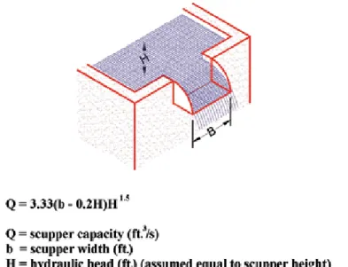
SCuPPeRS
The study of flow rates through rectan gular perimeter openings, scuppers, or weirs is a common subject in the study of fluid dynamics.6 Scuppers can be constructed with either an open top (a channel) or a closed top with four sides. The theoretical flow of water through channels has been reported by Griffin and Fricklas. (See Figure 2.)
Other groups have reviewed the proper ties of flow-through scuppers, including the American Society of Civil Engineers (ASCE)7 and RCI, Inc.8 Theoretical flow rates have been published for various channel/scup per configurations.
Four different sizes of through-wall scuppers were utilized for this study:
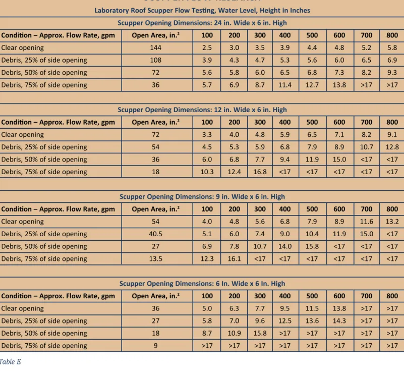
• 6 in. x 6 in. • 6 in. x 9 in. • 6 in. x 12 in. • 6 in. x 24 in. The scuppers were initially flooded with water at rates of 100 to 800 gpm until steady-state conditions were reached. Each configu ration was tested with a clear opening and then partially obscured at rates of 25%, 50%, and 75%. The height of water accumulation for each
combination of factors was measured. Data generated from the testing of the scuppers are included in Table E.
From a fluid dynamics standpoint, the flow rate characteristics change as the depth or accumulation of water increases. As the scupper is flooded, the water depth is less than the vertical element of the scupper. Water flows as in an open-sided channel. Once the scupper becomes sub merged, the flow rate characteristics change as a result of the increased hydraulic head and the friction with all four sides of the scupper.
Scupper flow rate characteristics are not
Figure 2 – The theoretical flow of water through channels has been explained by Griffin and Fricklas.
SCuPPeR flOW ReSeaRCH
laboratory Roof Scupper flow Testing, Water level, Height in Inches Scupper Opening Dimensions: 24 in. Wide x 6 in. High
Condition – approx. flow Rate, gpm Open area, in.2 100 200 300 400 500 600 700 800
Clear opening 144 2.5 3.0 3.5 3.9 4.4 4.8 5.2 5.8
Debris, 25% of side opening 108 3.9 4.3 4.7 5.3 5.6 6.0 6.5 6.9
Debris, 50% of side opening 72 5.6 5.8 6.0 6.5 6.8 7.3 8.2 9.3
Debris, 75% of side opening 36 5.7 6.9 8.7 11.4 12.7 13.8 >17 >17
Scupper Opening Dimensions: 12 in. Wide x 6 in. High
Condition – approx. flow Rate, gpm Open area, in.2 100 200 300 400 500 600 700 800
Clear opening 72 3.3 4.0 4.8 5.9 6.5 7.1 8.2 9.1
Debris, 25% of side opening 54 4.5 5.3 5.9 6.8 7.9 8.9 10.7 12.8
Debris, 50% of side opening 36 6.0 6.8 7.7 9.4 11.9 15.0 <17 <17
Debris, 75% of side opening 18 10.3 12.4 16.8 <17 <17 <17 <17 <17
Scupper Opening Dimensions: 9 in. Wide x 6 in. High
Condition – approx. flow Rate, gpm Open area, in.2 100 200 300 400 500 600 700 800
Clear opening 54 4.0 4.8 5.6 6.8 7.9 8.9 11.6 13.2
Debris, 25% of side opening 40.5 5.1 6.0 7.4 9.0 10.4 11.9 15.0 <17
Debris, 50% of side opening 27 6.9 7.8 10.7 14.0 15.8 <17 <17 <17
Debris, 75% of side opening 13.5 12.3 16.1 <17 <17 <17 <17 <17 <17
Scupper Opening Dimensions: 6 In. Wide x 6 In. High
Condition – approx. flow Rate, gpm Open area, in.2 100 200 300 400 500 600 700 800
Clear opening 36 5.0 6.3 7.7 9.5 11.5 13.8 >17 >17
Debris, 25% of side opening 27 5.8 7.0 9.6 12.5 13.6 14.3 >17 >17
Debris, 50% of side opening 18 8.7 10.9 15.8 >17 >17 >17 >17 >17
Debris, 75% of side opening 9 >17 >17 >17 >17 >17 >17 >17 >17
Table E Percentage of Primary Drain Blockage Percentage of Secondary Drain Blockage approximate Discharge at Roof Drain (gpm) approximate Discharge at Scupper (gpm) approximate accumulation at Roof Drain, Hydraulic Head (in.)
0 0 269 48 3.9 25% 0 264 53 5.1 50% 0 211 106 6.1 75% 0 151 166 7.1 100% 0 0 317 9.0 100% 25% 0 317 11.0 100% 50% 0 317 17.2 100% 75% 0 317 >18
Table F – Accumulation depending on blockage of test drain.
Cl ien t/F ilename: Fir es tone 2458 IS O T ra de Ad_4 .93 75x7 .5 Job #: AF IR E-2 458 Job N ame: Tr ade Ad - P olyi so CD: Siz e/Specs: 4. 93 75" x 7 .5" (h alf p age i sland); 4C AD : Ins er tion D ate: N ov embe r 2 01 3 CW: P ub: RC I A cct .S er v. 11 1 M o n u m e n t C ir c le , S u it e 4 15 0 / In d ia n a p o lis , IN 4 6 2 0 4 / t 31 7/ 6 3 2/ 6 5 0 1 / C VR in dy .c o m /
included within the building codes. In order to design a scupper with sufficient capabil ity to match the drainage requirements of the primary roof drainage system, reverse engineering may be required using either actual testing or available theoretical flow rate data.
PRImaRy – SeCONDaRy DRaIN mODel
One scenario was studied based on test data: a 6-in. primary drain with ¼-in. hor izontal leaders located in Orlando, Florida. Prior data show one drain for 6,795 sq. ft. of roof. In this situation, 317 gallons of water per minute would be generated during a 4.5-in.-per-hour rainfall event. If the sec ondary drainage system consists of 6- by 6-in. through-wall scuppers (1 in. higher than the primary drain), then the following accumulation would develop, depending upon the percentage of debris present at the primary roof drain. (See Table F.)
Based upon test data, a 6- by 6-in. through-wall scupper may not be sufficient, depending upon the live-load capability of the structural deck. When the primary roof drain is blocked, water accumulates up to 9 inches. This amount of water would create a live load that could not be supported by most structural decks.
CONCluSIONS
Several conclusions can be reached as a result of this study:
• Compliance with code requirements for drainage in new roofing and reroofing is critical for proper roof performance.
• In geographical areas prone to hur ricane events, designers should consider increasing the capacity of the drainage system due to poten tial blockage as a result of airborne debris.
• Periodic roof maintenance, includ ing debris removal, is necessary for proper roof drain and scupper performance. Removal of debris from the roof surface is the responsibility of the owner.
• “Green” roof assemblies most likely will require increased debris remov al to ensure proper and consistent drainage.
• Width is the dominant factor in flow-rate performance of roof scuppers. • The use of roof scuppers as the pri mary and secondary drainage sys
tems may require reverse engineer ing to determine the proper height and size. Flow rates through scup pers obviously are dependent upon the height of the water accumula tion. The depth of water and subse quent loading of the roof structure should be taken into consideration by the building designer.
RefeReNCeS
1. Eddie Garcia, “Got Drain?,” Western
Roofing, July 2009.
2. C.W. Griffin and R. Fricklas,
“Draining the Roof,” Chapter 3, Manual of Low-Slope Roof Systems, McGraw Hill, 2006.
3. International Building Code, 2006.
4. International Plumbing Code, 2006.
5. ANSI/SPRI RD-1, Performance
Standard for Retrofit Roof Drains, April 7, 2004.
6. Frank M. White, Fluid Mechanics,
7. American Society of Civil Engineers,
Flow Rate of Various Drainage Systems at Various Hydraulic Heads, ASCE 7-02, Page 338.
8. RCI Foundation, Roof Drainage,
Publi-cation No. 02.03.
This article was originally published in the Proceedings of the RCI 25th International Convention, March 25-30, 2010, Orlando, FL.
Jim D. Koontz, rrC, pe
Jim D. Koontz, president of Jim D. Koontz & Associates, Inc., is a graduate of Tulane University with a bachelor’s degree in engineering and a master’s in business administration. Koontz has been involved in the roofing industry since 1960 and began testing roofing materials in 1976. He has experi ence as a roofer, estimator, consultant, lecturer, researcher, and expert witness. He has been publishing articles related to roofing since 1984.
New mandatory green building regulations went into effect on October 1, 2013, in Dallas, Texas, intended to aggressively cut energy and water use with a goal of reaching carbon neutrality by 2030. The regulations are the culmination of the five-year Dallas Green Building Construction Ordinance for all new residential and commercial buildings.
New construction projects must meet either Leadership in Energy and Environmental Design (LEED®), Green Built Texas, or International Green Construction Code (IgCC) certification requirements.
To combat ongoing droughts, the regulations require that 70% of the built area for new homes either be permeable or capture runoff. All new homes may only use drip irrigation systems and must have high-efficiency fixtures. Commercial buildings are required to reduce water use by 20%, restrict outdoor lighting, and use cool or green roofing systems. New construction must divert at least 50% of waste material from landfills; and 45% of materials must be recycled, recyclable, bio-based, or locally sourced materials. Developers are required to pass a green builder certification exam.
The new regulations are expected to boost the regional economy, as building asset values rise when builders invest in sustainable development. To date, Dallas has more than 140 LEED-certified buildings, and 59 million sq. ft. of Energy Star-certified space.
— Cleantechnica.com
— Dallas goes green With Building Regulations —
RCI Foundation – United States
Web site: www.rcifoundation.org
E-mail: foundation@rci-online.org
The RCI Foundations –
Supporting The Industry
RCI Foundation – Canada
Web site: www.rcifoundation.ca
E-mail: info@rcifoundation.ca
R
ooftoppV S
yStemSG
ettinGC
heapeR According to a September report by the Solar Energy Industries Association (SEIA) and GTM Research, “the average cost of a solar panel…has dropped by 60% since 2011. The average residential PV system now costs only $4.81/watt, and the aver-age nonresidential system costs only $3.71/watt.”SolarCity, Verengo and Wall, and Trinity Solar have emerged as the leading mass-market installers, for a combined 29.8% of the residential solar installa-tion market in 2012.
At the same time, electric utilities, concerned that widespread installation of rooftop solar will reduce demand for utility-supplied electricity, are exploring how to enter the market.
In many states, laws allow only regulated utili-ties to sell power to customers. That remains a major hindrance to the expansion of rooftop solar across the U.S. Rooftop-solar leasing is thriving in states such as Arizona, Colorado, and Masschusetts, but it is illegal in most of the Southeast.
Competition is growing. Jonathan Bass, spokes-man for SolarCity in San Mateo, CA, says compa-nies will have to include high levels of customer service, fast and simple installation, and solar-power costs that are lower than what customers get from their local utilities.
— ENR