NFV ISG PoC Proposal
A.1
NFV ISG PoC Proposal
A.1.1 PoC Team Members
PoC Project Name:o Multi-vendor Distributed NFV
Network Operators/ Service Providers: o CenturyLink
Contact: Kevin McBride (Project Lead) (Kevin.M.Mcbride@centurylink.com)
Contact: Michael K Bugenhagen (Coordination Architect) (Michael.K.Bugenhagen@centurylink.com)
Manufacturer A:
o Certes Contact: Walt Halasowski (walt.halasowski@certesnetworks.com)
Manufacturer B:
o Cyan Contact: Nirav Modi (nirav.modi@cyaninc.com)
Manufacturer C:
o Fortinet Contact: Chris Lopez (clopez@fortinet.com)
Manufacturer D:
o RAD Contact: Yuri Gittik (yuri_g@rad.com)
This PoC will be conducted in several phases. This document provides detailed description of Phase 1 and outlines the Phase 2 scope. We are open to inclusion of other operators/vendors in our process subject to resource constraints in subsequent phases.
A.1.2 PoC Project Goals
Introduction
The advantages of Network Function Virtualization is well understood and several Proof-of-Concepts (PoC) are being developed based on centralized NFVI architectures and centralized VNF deployment. This type of centralized
architecture leverages economies of scale and enables efficient resource sharing. VNFs such as virtualized BGP route-reflectors, virtualized evolved-packet core (EPC), virtualized IP multimedia-subsystem (IMS) are traditional distributed in a few physical locations today and can benefit from high-scale and centralized NFVI.
However, there is also a need to deploy some functions out at the customer edge – functions that don’t necessarily require the scale and elasticity available in a large-scale centralized NFVI, and conversely, require highly specialized and often localized configuration and deployment. The ability to support the deployment of virtualized functions at the customer edge requires a Distributed NFV (D-NFV) architecture. D-NFV enables the placement of virtualized network functions (VNFs) throughout the network, where they are most effective and highly customized to a specific application or user. VNFs may be located in data centers, network nodes and at the customer premises. Running VNFs at the customer site is justified in certain cases, for example, when the network function is most effective when located as close as possible to the end-user. Such is the case for firewalls, diagnostic tools, WAN optimizer, security encryption, NATs, to name a few. An omniscient D-NFV orchestrator handles all VNFs and virtual machine (VM) infrastructure, wherever they may be located, and exploits SDN-like mechanisms to achieve optimal VNF placement.
It is well-understood that the NFV Orchestration platform must be designed to be network-function and vendor neutral. This flexible approach enables network operators to deploy best-in-breed VNFs, without creating management and operational silos that are so prevalent in their networks today.
This PoC aims to validate the requirements, behaviour as well as general architecture (interfaces, associated information models, etc.) of an innovative and open D-NFV deployment model comprised of multiple vendors collaborating to deliver various physical and virtual components and single/multi-function VNFs that are deployed in high-volume. This PoC will demonstrate:
1. The Cyan orchestrator that manages and orchestrates a network comprised of a physical (NID and VM infrastructure) and virtual (firewall and encryption appliances) components.
2. The RAD NID with built-in compute infrastructure that integrates physical and virtual components and enables NFV deployment at the customer edge (site).
3. The Fortinet next generation firewall and unified threat management functions are delivered as VNFs utilizing FortiGate VM appliances and virtual domains (VDOMs) to support dynamic routing protocols in both IPv4 and IPv6 (including BGP and OSPF) networks, providing separate security policies, enhanced levels of security and data segregation needed, including running VNFs at the customer premises for improve service delivery.
4. How the Certes Networks virtual encryptors (vCEPs) can be deployed by an NFV orchestration platform and coexist successfully with other VNF’s while being customized by the end user. The vCEP will be able to encrypt and decrypt network traffic via L2, L3 or L4 using standard AES 256bit cipher and can be either be point to point or point to multipoint. The control of the keys and policies can be managed by the end user using Certes Networks TrustNet Manager, the key and policy manager.
PoC Phase 1 Goals
PoC Project Goal #1: Validate suitability of the ETSI NFV ISG architecture framework, as described in ETSI GS NFV 002 v1.1.1 (2013-10) for a multi-NFVI distributed environment, comprised of both centralized and remote virtualized resources.
PoC Project Goal #2: Demonstrate real-world deployable VNF cases, specifically the vE-CPE solutions (defined in Use Case #2 in ETSI GS 001 “Use Cases” document), based on D-NFV deployment at the customer edge. These cases include the following VNFs:
Firewall
Encryption engine
PoC Project Goal #3: Demonstrate the orchestration components required to realize a distributed NFV (D-NFV) architecture, including:
Format and content of the VNF descriptor for two different VNFs (multi-vendor orchestration)
Variety of deployment topologies of VNFs and flows therein
Interactions with the virtualized infrastructure manager to organize/place and manage a distributed NFV environment
PoC Project Goal #4: Demonstrate service chaining between physical network functions (PNFs) and single/multiple VNFs. Specifically, MEF Carrier Ethernet (CE2.0) capabilities are service-chained with a virtual firewall or/and virtual encryption implemented as VNF . Such implementation will also
demonstrate possibility to provide multiple service offering with different options per-flow service creation.
PoC Project Goal #5: Test and document the inter-VNF interactions and work required to ensure that two different VNFs, from independent VNF vendors can co-exist and function properly within a single D-NFV compute server (node).
PoC Project Goal #7: Validate the ability for OpenStack to support a D-NFV infrastructure and identify gaps and operational procedures that are required to support this innovative use-case.
PoC Subsequent Phase Goals
In subsequent phases of the PoC, we are open to including other operator sponsors as well as other VNF vendors. Focus in subsequent phases will be on the operational aspects of D-NFV as well as the orchestration of VNFs in a multi-domain environment, comprised of decentralized and centralized NFVIs.
A.1.3 PoC Demonstration
The PoC will be initially hosted in Cyan’s Lab located in Petaluma, California, USA, with a replicated environment being available in the CenturyLink Integrated Testing Facilities in Littleton, Colorado, USA. Demonstration of the PoC will occur at the following industry events:
Venue for the demonstration of the PoC:
Phase 1
Official - PoC Demo:
o Network Virtualization and SDN World, 27-30 May, 2014 (London) http://sdnworldevent.com/
Additional demonstrations:
o OpenStack Summit, 12-16 May, 2014
http://www.openstack.org/summit/openstack-summit-atlanta-2014/
Phase 2
The official scope and final timeline for Phase 2 are to be determined. The current plan is to showcase additional features and functionality for this D-NFV use-case in 2H2014.
A.1.4 Publication
What would be the publication channel(s) for the PoC. The PoC results document will be published to the ETSI NFV ISG mailing group as well as on the PoC participant (operator sponsor and vendors) websites.
What would be the planned publication date(s)? A PoC report will be published after each completed phase. The target date for the Phase 1 report is 1 August, 2014.
URLs where applicable: TBD
A.1.5 PoC Project Timeline
What is the PoC start date: The project is already in progress.
Demonstration target date: 27-30 May, 2014 (http://sdnworldevent.com)
PoC Report target date: 1 August, 2014
When is the PoC considered completed: Phase 1 completion date once the PoC report has been published on 1 August, 2014.
A.1.6 Call for Participation for Phase 2
In 2H2014, we are planning to augment the PoC platform with other VNFs to show additional uses cases. The
additional use-cases will include NFV orchestration of both centralized and decentralized NFVI resources – effectively combining D-NFV with centralized DC-based NFV deployment. Phase 2 will also focus on the operational aspects of NFV.
Other service providers who are interested in D-NFV architectures and use-cases are also invited to become sponsors and submit their use-cases.
A.2
NFV PoC Technical Details
A.2.1 PoC Overview
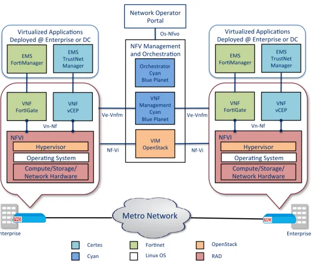
The following diagram illustrates the functional components that will make up the multi-vendor, multi-function D-NFV PoC for Phase 1. For Phase 2, we will include centralized NFVI.
Figure 1: Overall PoC Framework for Phase 1
Metro Network
Enterprise Enterprise NFV Management and Orchestra on Orchestrator Cyan Blue Planet VNF Management Cyan Blue Planet VIM OpenStack NFVI Compute/Storage/ Network Hardware Hypervisor VNF For Gate VNF vCEP Vn-Nf EMS For Manager EMS TrustNet Manager NFVI VNF For Gate VNF vCEP Vn-Nf EMS For Manager EMS TrustNet Manager Nf-Vi Ve-Vnfm Nf-Vi Ve-Vnfm For net Certes RAD Cyan OpenStack Opera ng System Compute/Storage/ Network Hardware Hypervisor Opera ng System Linux OSVirtualized Applica ons Deployed @ Enterprise or DC
Virtualized Applica ons Deployed @ Enterprise or DC Network Operator
Portal
NFV Component Vendor Contribution
NFVI1 RAD ETX-205A/NFV
(Virtualized with OpenStack/KVM hypervisor) NFVI2 Centrally located x86 server serving VIM function
(OpenStack Controller)
VIM OpenStack
VNF1 Certes vCEP (virtual encryption) VNF2 Fortinet FortiGate (virtual firewall)
EMS1 Certes TrustNet Manager
EMS2 FortiManager
VNF Manager(s) Cyan Blue Planet
NFV Orchestrator Cyan Blue Planet
Table 1: PoC Components
A.2.2 PoC Scenarios
Phase 1 Scenarios
Scenario 1 – Service Definition
Demonstrate how a Service Provider administrator can define and create two service offerings for their Enterprise Customers. The products that the Service Provide would sell are described below.
1. Firewall Service 2. Encryption Service
Demonstrate the flexibility and innovation enabled by NFV – an a la carte offering of services, both via a portal and via RESTful APIs that can be leveraged by the enterprise-customer – thus enabling a level of automation that is absolutely not possible in a PNF-based solution.
Scenario 2 - VNF Instantiation
Demonstrate the instantiation of the specified VNF when a enterprise customer has selected on of the products offered by the Service Provider. This scenario includes the service-chaining and assembly of a VNF-FG between the virtual firewall and virtual encryption appliances, as well as the instantiation of either VNF on it’s own.
We will also demonstrate powerful service applications where multiple service chains are created:
Flows that filtered through the firewall (e.g. internet-bound traffic)
Flows that are encrypted/decrypted (e.g. inter-Enterprise traffic)
Flows that pass transparently through the CPE (e.g. flows that may be subject to policy enforcement in a DC or centralized enforcement point).
This type of capability requires rich and flexibility classification capabilities on the vE-CPE devices, and intelligent orchestration of the service-chain.
and virtual encryption applications will be identified and documented. The information models required (consumed by the orchestrator), network service description, VNF descriptors and VNF-FG models will be presented.
Orchestration of the encryption engine:
1. The Certes management implementation uses a single console to administer multiple encryption enforcement points. This simplifies policy management and maintenance.
2. Logging and report functions of the encryption engines will also be demonstrated.
Scenario 3 - VNF Fault and Performance Management
In an D-NFV architecture, redundancy may not always be available nor offered. However, it is still important to detect, isolate and report failure events and conditions and if possible pre-emptively act before the failure. In this scenario we will demonstrate the management and orchestration of the following:
o VNF Fault o NFVI Fault
o Performance monitoring (VM/CPU utilization for each VNF, as well as any other specified KPIs by the VNF vendor)
Recovery may often not be possible in case of D-NFV since there may not be redundant compute (server) hardware available at edge deployment (NFVI). Nevertheless, we will explore recovery techniques (some last-resort techniques) as well as concepts such as “dying-gasp” to alert the orchestrator of impending failure.
Scenario 4 - D-NFV NFVI Deployment
One of the fundamental challenges with D-NFV is management of the distributed NFVI. This includes discovery and boarding of NFVI as well as the management thereafter. As part of this scenario, we will demonstrate the on-boarding of a new distributed compute node (server) and identify the interface requirements between the orchestrator and the VIM to perform the turn-up of a new compute node. In Phase 1, some base assumptions will be made regarding the nature of the remote device and available computing platform. In a subsequent phase, we will study the possibilities to auto-discover and on-board the NFVI.
Phase 2 Scenarios
The tentative plan for the Phase 2 is to enhance the architecture with centrally-located VNFs (in addition to the VNFs at the customer edge) and add new capabilities, in order to explore the following scenarios:
o Orchestration of a subset of the Phase 1 scenarios between a D-NFVI and centralized NFVI – showing the flexibility of a multi-domain orchestration platform, the rich services enabled by vE-CPEs, as well as the versatility of the firewall and encryption VNFs.
o Auto-discovery of NFVI type, on-boarding of NFVI
o Power-saving modes – selective power-down of components when not in use or during idle periods o Migration of applications/services between centralized and distributed NFVI
o Fault isolation/recovery, including VNF chain-rebuilding, migration to centralized NFVI as a work-around, etc.
o High-availability o VNF scaling
o Certes encryption engine allows dynamic reallocation of x86 resources (CPU cores, for example) o VNF load-balancing
o Orchestration of multiple VNFs (e.g. Certes encryption engine) and load-balancing across the VNF instances
o VNF snapshotting (rapid backup/restore for VNF + configuration) o VNF commissioning performance test/birth certificate (turn-up and test)
In Phase 2 we will introduce a combination of both central and remote VNF deployment. As such, we will demonstrate the orchestration of VNFs across vE-CPEs and a central DC location. The following figure shows this topology.
Virtualized Applica ons Deployed @ Enterprise or DC Virtualized Applica ons
Deployed @ Enterprise or DC
Metro Network
VNF For Gate VNF vCEP Vn-Nf EMS For Manager EMS TrustNet Manager VNF For Gate VNF vCEP Vn-Nf EMS For Manager EMS TrustNet Manager Nf-Vi Ve-Vnfm Nf-Vi Ve-VnfmData Center
NFVI Compute/Storage/ Network Hardware Hypervisor Opera ng System NFVI Compute/Storage/ Network Hardware Hypervisor Opera ng System NFV Management and Orchestra on Orchestrator Cyan Blue Planet VNF Management Cyan Blue Planet VIM OpenStack Network Operator Portal Os-NfvoA.2.3 Mapping to NFV ISG Work
Describe how this PoC relates to the NFV ISG work:1) Specify below the most relevantNFV ISG end-to-end concept from the NFV Use Cases [Error! Reference source not found.], Requirements [Error! Reference source not found.], and Architectural Framework functional blocks or reference points [Error! Reference source not found.] addressed by the different PoC scenarios:
Use Case Requirement E2E Arch Comments Scenario 2 UC#2 –
VNFaaS
This PoC will demonstrate the vE-CPE use-case
Scenario 2 UC#4 – VNF-FG
This PoC will demonstrate several unique
service-chains that span both PNFs and VNFs, as well as multiple service-flows through the same x86 HW showcasing the flexibility of the D-NFV
architecture and innovation enabled by NFV
A.2.4 PoC Success Criteria
This proof-of-concept will be conducted in phases. As such, Phase 1 will be considered successful when all included scenarios have been successfully implemented, integrated and demonstrated and findings published in the PoC report.
A.2.5 Expected PoC Contribution
List of contributions towards specific NFV ISG Groups expected to result from the PoC Project:
PoC Project Contribution #1: VNF on-boarding requirements and process NFV Group: MAN
PoC Project Contribution #2: Orchestrator/VIM interface requirements NFV Group: MAN