operator
701P24790
April, 2005
Global Knowledge and Language Services 800 Philips Road Bldg. 845-17S
Webster, New York 14580 USA
©2005 by Xerox Corporation. All rights reserved.
Copyright protection claimed includes all forms and matters of copyrightable material and information now allowed by statutory judicial law or hereinafter granted, including without limitation, material generated from the software programs displayed on the screen such as icons, screen displays, or looks.
Printed in the United States of America.
XEROX® and all Xerox product names mentioned in this publication are trademarks of XEROX CORPORATION. Other company trademarks are also acknowledged.
Changes are periodically made to this document. Changes, technical inaccuracies, and typographic errors will be correctedin subsequent editions.
Table of contents
Safety
Laser safety . . . v
Ozone information: U. S. only . . . v
Operation safety: U. S. . . . v
Operation safety: Europe . . . .vi
Warning markings . . . vii
Electrical supply . . . vii
Ventilation . . . vii
Operator accessible areas . . . viii
Maintenance . . . viii
Before cleaning your product . . . viii
CE mark: Europe only . . . viii
Radio and telecommunications equipment directive (Europe only) . . . .ix
For further information . . . x
Introduction
About this guide . . . .xiContents . . . .xi
Conventions . . . .xi
Documentation . . . xii
DocuPrint 100/115/135/155/180 EPS documentation . . . xiii
1 Overview
Functional overview . . . 1-1 Host connectivity options . . . 1-2 Data formats supported . . . 1-3 Stock specifications . . . 1-3 Stock sizes . . . 1-4 Paper weights . . . 1-4 Special stocks . . . 1-5 General paper characteristics to look for . . . 1-5 Printing process and job flow . . . 1-6 Printer overview . . . 1-8 Printer components . . . 1-10 Processor Feeder Trays . . . 1-10 Sample tray . . . 1-10 Attention light . . . 1-11 Purge tray . . . 1-11 Feeder trays . . . 1-11 Stacker bins . . . 1-12 Feeder/stacker modules . . . 1-14 Printer control console (not shown). . . 1-15 Printer configurations . . . 1-15 Printer options . . . 1-16 Bypass transport . . . 1-16 Support and interface with feeders . . . 1-17
7 by 10 inch enablement kit . . . 1-18 Paper paths . . . 1-18 Printer paper path . . . 1-18 Bypass transport paper path . . . 1-20 Controller overview . . . 1-20 Controller components . . . 1-21 Sun workstation. . . 1-21 External components and options. . . 1-26 Controller stand . . . 1-26 Online and offline interfaces . . . 1-26 Moving the controller . . . 1-27 Tape drives overview . . . 1-29 Paper sizing and print speed . . . 1-30 Long and short edge feeding . . . 1-31 Paper width and throughput speed (LCDS printing only) . . . 1-31 Paper size and pitch mode minimum and maximum . . . 1-33 Feed direction for standard paper sizes . . . 1-35
2 Managing the printer
Controlling the printer . . . 2-1 Interrupting printing . . . 2-1 Resuming printing . . . 2-1 Powering on the printer . . . 2-1 Powering off the printer . . . 2-1 Powering off the printer immediately . . . 2-2 Adjusting the registration transport roll levers for heavy paper . . . 2-2 Loading paper . . . 2-3 Unloading a stacker bin . . . 2-8
3 Managing the system
Starting, stopping, and rebooting the system . . . 3-1 Powering on the controller . . . 3-1 Powering on the printer . . . 3-1 Holding queues . . . 3-2 Releasing queues . . . 3-2 Rebooting the system (warm boot) . . . 3-2 Performing a deferred shutdown and reboot . . . 3-3 Performing an immediate shutdown and reboot . . . 3-3 Restarting the DocuSP software . . . 3-4 Powering off the system . . . 3-4 Performing an emergency power off . . . 3-5 Powering off the controller . . . 3-5 Powering off the printer . . . 3-6 Operating the 18/36 track tape drive . . . 3-7 Powering on the tape drive . . . 3-7 Powering off the tape drive . . . 3-8 Placing the tape drive online . . . 3-9 Loading a tape . . . 3-9 Unloading a tape . . . 3-10 Guidelines for handling cartridges . . . 3-11 Setting file protection . . . 3-12 Printing the online Help documentation . . . 3-13
4 Maintaining the system
Paper care . . . 4-1 Storing paper . . . 4-1 Conditioning paper . . . 4-3 Paper curl . . . 4-3 Using consumables . . . 4-4 Adding fuser agent . . . 4-4 Replacing the dry ink waste container . . . 4-7 Replacing the dry ink cartridge . . . 4-11 Using the custom transfer assist blade . . . 4-13 Cleaning the system and its components . . . 4-14 Cleaning the 18/36-track cartridge tape drive . . . 4-15 Cleaning the 26-track cartridge tape drive . . . 4-15 Cleaning the DVD drive . . . 4-16 Cleaning the diskette drive . . . 4-16 Cleaning the sensors and the reflecting surfaces . . . 4-16 Cleaning the Q850 sensor . . . 4-16 Cleaning the Q1011 sensor and mirror . . . 4-18 Cleaning additional sensors . . . 4-19 Cleaning the display . . . 4-22 Cleaning the exterior surfaces of the system . . . 4-225 Troubleshooting
Undeclared faults . . . 5-1 Problem classifications . . . 5-1 Troubleshooting client problems . . . 5-2 Solving FreeFlow Prepress problems . . . 5-2 Troubleshooting Graphical User Interface (GUI) problems . . . 5-2 Troubleshooting print quality problems . . . 5-3 Resolving print quality problems on a PostScript job . . . 5-3 Isolating and resolving printer-driven print quality problems . . . 5-4 Resolving font problems . . . 5-4 Troubleshooting job flow problems . . . 5-5 Troubleshooting job integrity problems . . . 5-5 Troubleshooting PDL problems . . . 5-6 Isolating HP PCL file problems . . . 5-6 Isolating PostScript file problems . . . 5-6 Isolating TIFF file problems. . . 5-7 Isolating PDF file problems . . . 5-8 Troubleshooting process problems . . . 5-8 Troubleshooting productivity and performance problems . . . 5-9 Troubleshooting problems with saving jobs . . . 5-10 Crash recovery . . . 5-10 Streaming mode . . . 5-10 UI recovery messages . . . 5-11 Recovery message examples . . . 5-11 Spooling mode . . . 5-12 Points to note . . . 5-12 Clearing online print data . . . 5-13 Online gateway faults/submitting a job from the host . . . 5-13 Obtaining information about a job . . . 5-14 Data type on the Online Manager window . . . 5-15 Streaming queue release setup . . . 5-15 Incorrect printer state on host . . . 5-15
Clearing paper jams . . . 5-15 Aids to paper jam clearance . . . 5-16 Clearing paper jams in all printer areas . . . 5-16 Checking job integrity following a paper jam . . . 5-17 Clearing paper jams in printer areas 2 through 20 . . . 5-18 Clearing a paper jam in the bypass transport . . . 5-29 Clearing a misfeed (feeder tray fault) . . . 5-31 Troubleshooting frequent misfeeds (processor feeder trays) . . . 5-33 Incorrect paper size message . . . 5-36 Generating a test page . . . 5-36 Troubleshooting stacker problems . . . 5-37 Troubleshooting paper curl problems . . . 5-37 Checking paper curl . . . 5-37 Adjusting the decurler lever . . . 5-40 Troubleshooting the 36-track tape drive . . . 5-41 Performing basic recovery . . . 5-41 Troubleshooting initial program load (IPL) failure . . . 5-41 Solving other cartridge tape drive problems . . . 5-42 Calling for service . . . 5-45
6 Supplies
Available supplies . . . A-1 How to order supplies . . . A-5
Safety
Laser safety
WARNING: Adjustments, use of controls, or performance of
procedures other than those specified herein may result in hazardous light exposure.
The Xerox DocuPrint printers are certified to comply with the performance standards of the U.S. Department of Health, Education, and Welfare for Class 1 laser products. Class 1 laser products do not emit hazardous radiation. The DocuPrint printers do not emit hazardous radiation because the laser beam is completely enclosed during all modes of customer operation. The laser danger labels on the system are for Xerox service representatives and are on or near panels or shields that must be removed with a tool.
DO NOT REMOVE LABELED PANELS OR PANELS NEAR LABELS. ONLY XEROX SERVICE REPRESENTATIVES HAVE ACCESS TO THESE PANELS.
Ozone information: U. S. only
This product produces ozone during normal operation. The amount of ozone produced depends on copy volume. Ozone is heavier than air. The environmental parameters specified in the Xerox installation instructions ensure that concentration levels are within safe limits. If you need additional information concerning ozone, call 1-800-828-6571 to request the Xerox publication 600P83222, OZONE.
Operation safety: U. S.
Your Xerox equipment and supplies have been designed and tested to meet strict safety requirements. They have been
approved by safety agencies, and they comply with environmental standards. Please observe the following precautions to ensure your continued safety.
WARNING: Improper connection of the equipment grounding
conductor may result in risk of electrical shock.
• Always connect equipment to a properly grounded electrical outlet. If in doubt, have the outlet checked by a qualified electrician.
• Never use a ground adapter plug to connect equipment to an electrical outlet that lacks a ground connection terminal. • Always place equipment on a solid support surface with
adequate strength for its weight.
• Always use materials and supplies specifically designed for your Xerox equipment. Use of unsuitable materials may result in poor performance and may create a hazardous situation. • Never move either the printer or the controller without first
contacting Xerox for approval.
• Never attempt any maintenance that is not specifically described in this documentation.
• Never remove any covers or guards that are fastened with screws. There are no operator-serviceable areas within these covers.
• Never override electrical or mechanical interlocks.
• Never use supplies or cleaning materials for other than their intended purposes. Keep all materials out of the reach of children.
• Never operate the equipment if you notice unusual noises or odors. Disconnect the power cord from the electrical outlet and call service to correct the problem.
If you need any additional safety information concerning the equipment or materials Xerox supplies, call Xerox Product Safety at the following toll-free number in the United States:
1-800-828-6571
For customers outside the United States, contact your local Xerox representative or operating company.
Operation safety: Europe
This Xerox product and supplies are manufactured, tested and certified to strict safety regulations, electromagnetic regulations and established environmental standards.
Any unauthorised alteration, which may include the addition of new functions or connection of external devices, may impact the product certification.
Please contact your Xerox representative for more information.
Warning markings
All warning instructions marked on or supplied with the product should be followed.
This WARNING alerts users to areas of the product where there is the possibility of personal damage.
This WARNING alerts users to areas of the product where there are heated surfaces, which should not be touched.
Electrical supply
This product shall be operated from the type of electrical supply indicated on the product’s data plate label. If you are not sure that your electrical supply meets the requirements, please consult your local power company for advice.
This product must be connected to a protective earth circuit. This product is supplied with a plug that has a protective earth pin. This plug will fit only into an earthed electrical outlet. This is a safety feature. Always connect equipment to a properly grounded electrical outlet. If in doubt, have the outlet checked by a qualified electrician.
To disconnect all electrical power to the product, the disconnect device is the power cord. Remove the plug from the electrical outlet.
Ventilation
Slots and opening in the enclosure of the product are provided for ventilation. Do not block or cover the ventilation vents, as this could result in the product overheating.
This product should not be placed in a built-in installation unless proper ventilation is provided, please contact your Xerox
representative for advice.
Never push objects of any kind into the ventilation vents of the product.
Operator accessible areas
This product has been designed to restrict operator access to safe areas only. Operator access to hazardous areas is restricted with covers or guards, which would require a tool to remove. Never remove these covers or guards.
Maintenance
Any operator product maintenance procedures will be described in the user documentation supplied with the product. Do not carry out any maintenance on the product, which is not described in the customer documentation.
Before cleaning your product
Before cleaning this product, unplug the product from the electrical outlet. Always use materials specifically designated for this product, the use of other materials may result in poor performance and may create a hazardous situation. Do not use aerosol
cleaners, they may be flammable under certain circumstances.
CE mark: Europe only
January 1, 1995: Council Directive 73/23/EEC, amended by Council Directive 93/68/EEC, approximation of the laws of the member states related to low voltage equipment.
January 1, 1996: Council Directive 89/336/EEC, approximation of the laws of the member states related to electromagnetic
compatibility.
March 9, 1999: Council Directive 99/5/EC, on radio equipment and telecommunications terminal equipment and the mutual
recognition of their conformity.
A full declaration of conformity, defining the relevant directives and referenced standards, can be obtained from your Xerox
representative.
In order to allow this equipment to operate in proximity to Industrial, Scientific and Medical (ISM) equipment, the external
radiation for the ISM equipment may have to be limited or special mitigation measures taken.
This is a Class A product. In a domestic environment this product may cause radio frequency interference, in which case the user may be required to take adequate measures.
Shielded interface cables must be used with this product to maintain compliance with Council Directive 89/36/EEC.
Radio and telecommunications equipment directive
(Europe only)
Certification to 1999/5/EC Radio Equipment and Telecommunications Terminal Equipment Directive:
This Xerox product has been self-certified by Xerox for pan-European single terminal connection to the analog public switched telephone network (PSTN) in accordance with Directive 1999/5/ EC.
The product has been designed to work with the national PSTNs and compatible PBXs of the following countries:
In the event of problems, contact your local Xerox representative in the first instance.
This product has been tested to, and is compliant with, TBR21, a specification for terminal equipment for use on analog switched telephone networks in the European Economic area.
The product may be configured to be compatible with other country networks. Please contact your Xerox representative if your product needs to be reconnected to a network in another country. This product has no user-adjustable settings.
NOTE: Although this product can use either loop disconnect (pulse) or DTMF (tone) signaling, it should be set to use DTMF signaling. DTMF signaling provides reliable and faster call setup.
Modification or connection to external control software, or to external control apparatus not authorized by Xerox, invalidates its certification.
• Austria • Germany • Luxembourg • Sweden • Belgium • Greece • Netherlands • Switzerland • Denmark • Iceland • Norway • United Kingdom • Finland • Ireland • Portugal
For further information
For more information on Environment, Health and Safety in relation to this Xerox product and supplies, please contact the following customer help lines:
Europe: +44 1707 353434 USA: 1 800 8286571 Canada: 1 800 8286571
Introduction
This document provides information on how to perform operator tasks for the DocuPrint 100/115/135/155/180 Enterprise Printing System (EPS).
About this guide
Before using this documentation, become familiar with its contents and conventions.
Contents
This guide contains the following:
• Chapter 1, “Overview,” provides a functional overview of the system; describes the controller and printer components; and explains the printing process, and the job flow.
• Chapter 2, “Managing the printer,” provides information specific to the printer, including management of paper stock and programming of the various trays.
• Chapter 3, “Managing the system,” provides management-related information that pertains to the system as a whole, such as starting, stopping, and rebooting the system and operating the tape drives.
• Chapter 4, “Maintaining the system,” provides information on adding and replacing consumable supplies, such as dry ink, and on cleaning the various areas of the system, including the tape drives.
• Chapter 5, “Troubleshooting,” provides information that will assist users in solving problems.
• Appendix A, “Supplies,” provides a summary of the paper that are used most often and the necessary supplies, their order numbers, and how to order them from Xerox.
• An index is provided at the end of this document.
Conventions
• Initial capital and angle brackets: Within procedures, the
names of keys are shown with an initial capital and within angle brackets (for example, press <Enter>).
• Angle brackets: Variable information, or the position of a
specified argument in the command syntax, appears in angle brackets (for example, List Fonts <pattern>).
• Fixed pitch font: Within procedures, text and numbers that
you enter are shown in a bold, fixed pitch (“computer”) font (for example, enter privilege operator).
• Messages that appear on the controller screen are shown in the medium weight fixed pitch font (for example, Online Gateway disabled).
• The word “enter” within procedures: The two-step process
of keying in data and pressing <Enter> (for example, enter y).
• Italics: Document and library names are shown in italics (for
example, the Xerox DocuPrint NPS/IPS Guide to Managing
Print Jobs).
Variable elements in a command or directory path are also shown in italics (for example, var/spool/XRXnps/ filename).
• Vertical bars: Alternatives to specified arguments are
separated by vertical bars (for example, Set Time <Time | Remote Host Name | IP Address>).
NOTE: Notes are hints that help you perform a task or understand the text.
CAUTION: Cautions alert you to an action that could damage
hardware or software.
WARNING: Warnings alert you to conditions that may affect the
safety of people.
Documentation
DocuPrint 100/115/135/155/180 EPS documentation
The following documents contain information on the Xerox DocuPrint 100/115/135/155/180 EPS:
• Customer Documentation CD
• Xerox DocuPrint 100/115/135/155/180 EPS Operator Guide • Xerox Document Services Platform Using LCDS Print
Description Language
• Xerox DocuPrint 100/115/135/155/180 EPS Installation Planning Guide
• Xerox DocuPrint 100/115/135/155/180 EPS NPS/IPS Extension Operations Guide
• Xerox DocuPrint EPS Font Reference Manual
• Xerox DocuPrint 100/115/135/155/180 EPS Operator Quick Reference Card
• Xerox DocuPrint 100/115/135/155/180 EPS Customer Information Quick Reference Card
• Xerox DocuPrint 100/115/135/155/180 EPS Job Submission Quick Reference Card
1
Overview
This chapter provides a functional overview of the entire system, as well as an overview of the controller and the printer portions of the system.
Functional overview
The Xerox DocuPrint 100/115/135/155/180 EPS prints high quality, high resolution monochrome documents in simplex or duplex mode at high production speeds, from LCDS, PostScript, PCL, and other data streams. The system can switch between printing different types of data streams without a need for rebooting or reconfiguring software.
The printer supports: • Duplex printing
• Media handling of multiple weights, sizes, and types
• Optional modules for enhanced finishing and output to third-party finishing devices
• Optional enabling of a third-party roll feeder
• Optional high-capacity feeder/stacker modules, which provide additional feeder trays and output bins
• High resolution of LCDS, PostScript, and PCL data streams (shown in the following table)
Table 1-1 Data stream resolution
* Requires additional equipment to enable.
** 600 by 600 dpi input resolution supported for full page IOCA only
Data
stream Input resolution
Print resolution: DP155 and DP180
Print resolution: DP100, DP115,
and DP135
LCDS 300 by 300 dpi 600 x 2400 dpi 600 by 600 dpi PostScript and PCL 300 by 300 dpi or 600 by 600 dpi 600 x 2400 dpi 600 by 600 dpi IPDS* 240 by 240 dpi* or 300 by 300 dpi or 600 by 600 dpi** 600 x 2400 dpi 600 by 600 dpi
Host connectivity options
The Xerox DocuPrint 100/115/135/155/180 EPS can receive data from a host in the following ways:
• Over a channel with bus and tag cable connection • Through a network interface, using Novell, TCP/IP, or
AppleTalk protocols
Your system may have one or both of these configurations.
Figure 1-1 Configurations supported for the Xerox DocuPrint 100/115/135/155/180 EPS
1. Sun UNIX client workstation
2. Apple Macintosh client workstation 3. Network connection
4. Controller
5. PC client workstation 6. Mainframe host computer
7. Bus and tag cables (channel connection) 8. Printer
Data formats supported
The Xerox DocuPrint 100/115/135/155/180 EPS can print the following data formats:
• ASCII • LCDS • PCL • PDF • PostScript • TIFF • IPDS • PPML
The system prints LCDS data from a mainframe host computer, emulating an IBM 4245 or 3211 page printer. The printing system can receive data over a channel through bus and tag cables, and through the Socket Gateway or lpr using TCP/IP protocol.
The system also prints PostScript and PCL data submitted over a network (Ethernet or AppleTalk) from a variety of clients:
• PCs (Windows and Windows NT) • Sun workstations (UNIX)
• UNIX command line clients: lp and lp
• NetWare Q-Server through a Novell print server (bindery mode only)
• Apple Macintosh workstations
Stock specifications
The success of any print run depends on proper selection, care, and handling of the paper or other stock that is used. It is very important to select, store, condition, and load print media properly in order to keep your printer running at optimum efficiency.
The printer functions best and produces the best print quality when using stocks that have the correct:
• Size • Weight • Type • Color
For more comprehensive information on paper stocks for Xerox printers, refer to Helpful Facts about Paper.
Stock sizes
The Xerox DocuPrint 100/115/135/155/180 EPS supports the following sizes of stock:
Table 1-2 Stock sizes
NOTE: To feed papers smaller than 8 inches / 203.2 mm in width, a 7 by 10 inch paper option kit must be installed.
Paper weights
The DP 100/115/135/155/180 EPS supports the following range of paper weights:
16–110 pound / 60–200 gsm
Other paper weights should not be used.
Name of
stock Size in inches Size in millimeters
Special requirements US Letter 8.5 by 11 inches 216 by 279 mm US Legal 8.5 by 14 inches 216 by 356 mm US Ledger US Tabloid 11 by 17 inches 17 by 11 inches 279 by 432 mm 432 by 279 mm A3 11.69 by 16.54 inches 297 by 420 mm A4 8.27 by 11.69 inches 210 by 297 mm B4 (European) 9.84 by 13.89 inches 250 by 353 mm JIS B4 (Japanese) 10.12 by 14.33 inches 257 by 364 mm ––
7 by 10 inches 178 by 254 mm With 7 by 10 inch option kit B5 7.17 by 10.12 inches 182 by 257 mm With 7 by 10 inch option kit
NOTE: The equivalent grams per square meter of 20 pound paper is actually 75 gsm. However, there is no standard 75 gsm paper. The available stock that is closest in weight to 20 pound paper is 80 gsm.
Special stocks
The following special stocks can be used with the DP 100/115/ 135/155/180 EPS:
• Labels: Must be the type designed for high-speed printers and
must meet the specifications described in the section above. Loading instructions are printed on all paper trays.
• Transparencies: Must be the type designed for high-speed
printers and must meet the specifications described in the section above. Loading instructions are printed on all paper trays.
• Colored paper: Available in a variety of colors, colored paper
has many uses, including calling attention to certain printed material, separating special sections, or dividing chapters of a report.
• Preprinted paper: May be letterhead, forms, or logos. (Refer
to Helpful Facts about Paper to verify that the preprinting inks used on your stock are the kind formulated for use in laser printers.)
• Predrilled paper: Has holes for use in binders or binder rings.
Before loading predrilled paper, fan it to remove any loose plugs that could cause paper jams.
• Perforated paper
• Precut or full tabs
• Carbonless paper
General paper characteristics to look for
When selecting paper, look for the following:
• Low moisture content (a paper to moisture ratio below 5.7 percent). Paper with higher moisture content may curl and jam.
• Smooth surface
• Moisture resistant wrapping
• No defects such as bent edges or uneven surfaces • Grain runs parallel with the long side of paper
Printing process and job flow
This section describes how the system software processes are used as a typical job flows through the system.
Figure 1-2 Job flow 1. Job
2. Input Queue 3. Decomposer 4. Output queue 5. Printer
Refer to the Job Flow diagram above for the following work flow process.
1. Job: The job and the job ticket (if applicable) are received from
the network by one of the protocol gateways.
2. Input queue: The Job Pool Manager (JPM) process transfers
the job into the input queue. The virtual printer name and job attributes are attached to the job. The job remains in the Input Queue until it can be printed; for example, “held” and “faulted” jobs reside in the input queue.
3. Decomposer: The Job Chooser (DC process) reconciles the
job attributes with the virtual printer attributes. Once the job is ready for print, the Job Chooser gives the job to the
appropriate decomposer (ps_cdf process, pcl_cdf process).
4. Output queue: After decomposition, the job is stored in the
output queue.
5. Printer: The marker (marker process) transfers the job from
printer). After the job has successfully printed, it is removed from the Output Queue and also from the Input Queue, if the Input Property for the queue is set to spool.
The ps –e or ps –ef commands can be used to list the system software processes. A varying process identification number is listed along with each process.
NOTE: The printing process and job flow is different for
PostScript, PCL, TIFF, ASCII, PDF jobs (that is, non-LCDS jobs) and for LCDS jobs.
PostScript, PCL, TIFF, ASCII, and PDF jobs
When the job is sent from the application for printing, a print data file is created. This file becomes the job that is submitted to the printer for printing. The print data file and the job request are submitted to the selected queue. Jobs are processed by priority within the designated queue once the job reaches the queue from a given application.
The following graphic illustrates the priority that each setting has in printing the job. For example, queue override settings in a job take precedence over exception page or job ticket settings.
Figure 1-3 Submission and print order of jobs in a queue 1. Queue overrides
2. Exception pages 3. Job ticket
4. Submission print protocol (lp, lpr, nprint) 5. Set page device values/PCL copy count 6. Queue defaults
You can make changes to the printing attributes of a PostScript, PCL, TIFF, ASCII, and PDF job (that is, a non-LCDS job), as long as the job is not streaming. This includes changing the type of paper on which it is printed or specifying printing order from last page to first (N to 1).
Printer overview
The printer receives data from the controller and prints the
document according to the print options specified by the user. The printer also stacks the printed output, collates it, and, if configured with one of the available optional third-party finishing devices, performs finishing functions such as binding, stitching, or perforating.
The Xerox DocuPrint 100/115/135/155/180 EPS printer is a monochrome printer. If it receives print jobs that contain color commands, it prints them in black or shades of gray.
Throughput speeds The Xerox DocuPrint 100/115/135/155/180 EPS prints LCDS data from a mainframe host computer, emulating an IBM 4245 or 3211 line printer. The printing system can receive data over a channel through bus and tag cables and through the Socket Gateway or lpr using TCP/IP.
Table 1-3 Throughput speeds
NOTE: Pages per minute refers to sides of a printed sheet (actually impressions per minute).
Using the smaller papers, such as 7 by 10 inch / 178 by 254 mm or B5, the printer can print at maximum speed. To print these sizes, the printer requires the optional small paper kit.
Monthly print volume
The monthly print volume for the Xerox DocuPrint Enterprise Printing Systems is up to 6 million impressions.
Table 1-4 Minimum and Maximum monthly print volume
Roll feeder support The roll feeder option may be installed in the inverter feeder/ stacker module, replacing the feeder tray. This option does not require DFA software or any additional hardware. The maximum number of feeder/stacker modules supported for this configuration is four, including the inverter module with the roll feeder. With the two processor feeder trays, this makes a total of six input trays possible.
Jam recovery The printer engine monitors the print job so that, if a paper jam occurs, the job resumes on the correct page, at the correct tab, using the same color paper, and so forth, providing complete document integrity.
Printing system throughputMaximum
Maximum throughput with 7 by 10 in / 178 by 254 mm paper DP100 EPS 100 ppm 100 ppm DP115 EPS 115 ppm 115 ppm DP135 EPS 135 ppm 154 ppm DP155 EPS 155 ppm 155 ppm DP180 EPS 180 ppm 206 ppm
Printing system Minimum Maximum
DP100 EPS 800 thousand 3 million DP115 EPS 1 million 3.5 million DP135 EPS 1.2 million 4 million DP155 EPS 1.4 million 4.5 million DP180 EPS 1.8 million 6 million
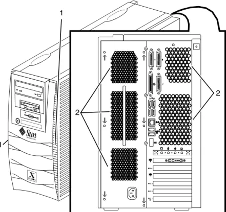
Printer components
The components and special features of the Xerox DocuPrint 100/ 115/135/155/180 EPS printer are shown in the following figure.
Figure 1-4 Printer components 1. Processor feeder trays 2. Sample tray
3. Attention light 4. Purge tray
5. Feeder/stacker module 6. Inverter feeder/stacker
NOTE: Some printer configurations may include a control console (not shown).
Processor Feeder Trays
Two processor feeder trays (trays 1 and 2) are located in the main part of the printer and are not part of a feeder/stacker module. Trays 1 and 2 can handle paper sized from 8 by 10 inches / 203 by 254 mm to 9.02 by 14.02 inches / 230 by 356 mm.
Sample tray
The sample tray, located on top of the printer, receives output such as transparencies, sample sheets from printing jobs, prints from system files such as forms, and waste sheets that cannot be sent to the purge tray.
Monitor the sample tray and empty it when it contains 100 sheets.
Attention light
An Attention light is mounted on top of the inverter module. This light either blinks or modulates (alternately brightens and dims) when the printer requires operator attention. The light has three states:
• Off: No printer problems exist that require attention.
• Steady light: A situation exists that needs attention soon.
• Flashing: The printer has stopped and requires your attention
immediately.
NOTE: When the Attention light starts flashing, an explanatory message appears in the Console window on the controller screen.
Purge tray
The purge tray is located on top of the last feeder/stacker module. Aborted sheets (for example, damaged sheets or sheets cleared after a paper jam) are sent to this tray. The purge tray should be emptied when it has received 100 sheets of paper.
NOTE: The system does not notify you when the tray is full.
Feeder trays
Multiple feeder trays can be configured to feed paper for jobs in the most effective manner. For example, the trays can provide nonstop printing of a complex job that requires many paper stocks, or only a few stocks, by using the trays continuous loading capability. A different input tray can also be selected for each copy of a specific page in a print job, for example, to provide different paper colors for specific pages.
The printing system may have up to six feeder trays: two processor feeder trays and two to four high-capacity trays. Four addressable input trays are standard with the system, and two additional high-capacity trays are optional.
Feeder tray capacity The feeder trays have the following capacities, based on 20 pound or 80 gsm (grams per square meter) paper:
• Tray 1: 1100 sheets
• Tray 2: 600 sheets
• Trays 3, 4, 5, and 6 (high-capacity trays): 2600 sheets each
An elevator moves each tray up or down when it is in use. In each tray, a control panel consisting of a button, indicators, and paper level displays controls the elevator tray and indicates its status.
Figure 1-5 Feeder tray control panel
1. Ready to Open indicator on feeder trays 2. Please Wait indicator on feeder trays 3. Tray Unlock button (feeder)
4. Paper Level indicators on feeder trays
Ready to Open indicator on feeder trays
Glows green when the tray can be pulled out and paper can be added to it.
Please Wait indicator on feeder trays
Shows that the tray is in motion. This indicator is lit red when the Tray Unlock button is pressed, while the tray is lowering, and while the tray is rising. The indicator goes off when the tray elevator reaches its destination.
Tray Unlock button (feeder)
Enables the feeder tray to be opened.
• If the tray is in use when this button is pressed, the feed selection switches to the backup tray if one has been identified. Otherwise, printing stops.
• If the tray is in use and selected as a backup tray, pressing the Tray Unlock button causes the tray elevator to lower and the tray to be unavailable for auto switching.
• If the tray elevator is in the raised position and the tray is not in use or selected as a backup tray, pressing this button causes the elevator to lower with no effect on printing operations. This button functions when the Please Wait indicator is off.
Paper Level indicators on feeder trays
Display the approximate quantity of paper in the tray. Each display shows paper by quarter reams up to one ream, and then by full reams. The green indicator appears above its Paper Level indicator.
Stacker bins
Each output stacker bin has offsetting capability and a capacity of 2500 sheets of 20 pound or 80 gsm paper.
NOTE: This capacity does not apply to 11 by 17 inch and A3 papers. Because of the additional weight these large sheets add to the bins, each bin is restricted to hold only up to 1500 sheets of A3 or 11 by 17 inch papers, for safety reasons.
Figure 1-6 High capacity stackers (HCS)
The stackers can stack the printed output in the bin three ways: • Directly onto the bin platform.
• Into a container that is set on top of the bin platform.
NOTE: The stacking capacity is approximately 100 to 150 sheets less when stacking into a container.
• Onto a pallet without a container (for paper sizes 11 by 17 inches or A3 only).
Using the Stacking windows on the user interface, you can select the level to which paper will be stacked in the HCS.
A stacking elevator maintains the paper at the proper level for stacking and lowers the stack for unloading. An offset mechanism offsets printed sets toward the front or back of the HCS bin. The elevator platform lowers under the following conditions: • The bin capacity has been reached.
• A selection to lower the platform is entered at the printer control console or a user interface window.
• The job being printed reaches a designated unload boundary. Each HCS bin has unlinked double doors to give you easy and safe access for unloading output from the printer.
The elevator bin platform automatically rises when the doors are closed after the stacker has been unloaded.
Bin control panels on stackers
Each stacker bin has a control panel consisting of buttons and indicators.
Figure 1-7 High capacity stacker bin control panel 1. Ready to Unload indicator on stacker bins
2. Please Wait indicator on stacker bins 3. Bin Unload button on stacker
4. In Use indicator on stacker bin
Ready to Unload indicator on stacker bins
When this indicator glows, you can remove printed sheets from the stacker bin.
Please Wait indicator on stacker bins
When this indicator glows, the elevator is in motion. This indicator turns off when the platform reaches its destination.
Bin Unload button on stacker
Lowers the bin elevator.
• If the bin is in use when this button is pressed, the printed pages begin stacking in the other stacker bin, if auto switching has been enabled.
• If the bin is not in use, pressing this button does not affect printing operations.
In Use indicator on stacker bin
When this indicator glows, the bin has been made ready to receive output.
Feeder/stacker modules
The feeder/stacker modules contain the high-capacity feeder trays and the stacker bins. The printer may have up to four feeder/ stacker modules (including the inverter feeder/stacker), containing feeder trays 3, 4, 5, and 6, and stacker bins A, B, C, and D. Each module contains one high-capacity feeder tray and one high capacity stacker bin.
High-capacity feeders
The high-capacity feeder (HCF) trays are located in the bottom half of the feeder/stacker modules. Each HCF tray can hold up to 2500 sheets of 20 pound or 80 gsm paper.
The high-capacity feeder trays can handle paper sized from 8 by 10 inches / 203 by 254 mm to 17 by 14.02 inches / 432 by 356 mm.
Unlike the processor feeder trays, the HCF trays have Paper Level switches, which detect the position of the elevator to determine the fullness of the tray.
High-capacity stackers
The high-capacity stacker (HCS) bins are located in the top half of the feeder/stacker modules, accessed through double doors. Two high-capacity stacker bins are standard, with up to two additional bins available as options (providing up to four bins total). Each bin holds up to 2500 sheets of 20 pound or 80 gsm paper.
Inverter The inverter is part of the inverter feeder/stacker module. It allows for proper collation of the print job. It also directs printed output to the sample tray, when required.
Printer control console (not shown)
Where available, the printer control console is the color monitor located on top of the printer. It keeps you informed of the printer status, and enables you to control certain functions of the printer, such as stopping printing and continuing an interrupted job, without returning to the controller.
Printer configurations
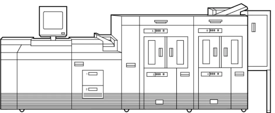
The standard printer configuration consists of an inverter feeder/ stacker plus one additional feeder/stacker. Some configurations may include a printer control console (not shown).
Figure 1-8 Printer with inverter feeder/stacker + feeder/stacker (standard base configuration)
In addition, the printer is available with three or four feeder/stacker modules.
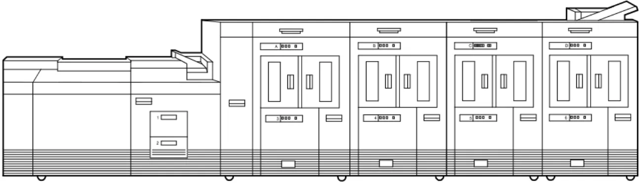
Figure 1-9 Printer with inverter feeder/stacker + feeder/stacker + feeder/stacker
Figure 1-10 Printer with inverter feeder/stacker + feeder/stacker + feeder/stacker + feeder/stacker
NOTE: The bypass transport device is not available for this configuration (four feeder/stacker modules).
Printer options
The printing system is available in several configurations, and may be connected to a bypass transport.
Bypass transport
The bypass transport option enables third-party finishing devices to interface directly with the printing system. The bypass transport allows you to customize your printer for increased efficiency and specialized applications involving finishing.
NOTE: A bypass transport must be installed for the printing system to support a third-party finishing device.
Function of the bypass transport
Connected to the last feeder/stacker module, the bypass transport moves paper from the stacker to a third-party finisher such as a stitcher, booklet maker, tape binder, and so on. By making selections on the display monitor, you can program the printer to send output to the bypass transport, which feeds the output to the finishing equipment.
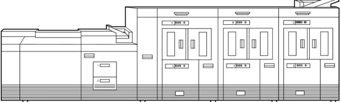
Figure 1-11 Printer with inverter feeder/stacker + feeder/stacker + bypass transport
Figure 1-12 Printer with inverter feeder/stacker + feeder/stacker + feeder/stacker + bypass transport
The illustrations above show a printer with two feeder/stacker modules and a bypass transport, and a printer with three feeder/ stacker modules and a bypass transport. With the bypass transport installed, the printer can support up to three feeder/ stacker modules, including the inverter feeder/stacker.
Paper stocks supported on bypass transport
The bypass transport accepts all paper stocks on which the printer can print, and it accommodates simplex and duplex printing.
DFA support The bypass transport meets the Xerox Document Feeding and Finishing Architecture (DFA) specifications. The system software supports DFA. However, in order for the bypass transport to function correctly, you need to set up finishing personality profiles to identify your finishing device to the printing system. (The customer support representative for your finishing device can give you the information you need to create a personality profile for your third-party finishing device.)
Support and interface with feeders
For information on marketing partners that provide solutions for support and interface with feeders, contact your local Xerox sales representative.
The input enablement device is NOT an option on the Xerox DocuPrint 155 and 180 EPS.
NOTE: The input enablement device is available only for the Xerox DocuPrint 100, 115, and 135 EPS.
7 by 10 inch enablement kit
The 7 by 10 inch enablement kit allows the printing system to print on 7 by 10 inch/178 by 254 mm paper size, with throughput speed of up to 206 PPM.
Paper paths
The paper path is the route that materials (paper, transparencies, labels, and so on) follow through the printer from the feeder trays to the output bins or finisher.
Printer paper path
The following figure shows the path the paper takes through the printer.
Figure 1-13 Route of paper through the printer 1. Processor feeder tray 1
2. Processor feeder tray 2 3. High-capacity feeder tray 3
a. Side 1 of sheet leaving feeder tray b. Drilled holes (on right edge) c. Origin 0,0: portrait orientation 4. High-capacity feeder tray 4
a. Side 1 of sheet leaving feeder tray b. Drilled holes (on right edge) c. Origin 0,0: portrait orientation 5. Inverter
6. Duplex inverter 7. Sample tray 8. Disk inversion
9. High-capacity stacker bin A a. Side 2 of sheet stacked in bin b. Drilled holes (on left edge) c. Origin 0,0: portrait orientation 10. High-capacity stacker bin B a. Side 2 of sheet stacked in bin b. Drilled holes (on left edge) c. Origin 0,0: portrait orientation
11. Purge tray 12. Bypass transport
a. Side 2 of sheet passing through bypass transport b. Drilled holes (on left edge)
c. Origin 0,0: portrait orientation
Bypass transport paper path
The following figure shows the paper path through the bypass transport, viewed from the front of the printer.
Figure 1-14 Bypass transport paper path 1. Sheet path
2. Exit rollers 3. Floor
Controller overview
The controller receives LCDS, PostScript, and PCL data streams from a mainframe host or a workstation client, processes the data, and sends it to the printer. The controller also provides the printer with print data and commands and receives status information from the printer.
The controller consists of a Sun Workstation computer, which is run by the Sun Solaris Operating environment. Also resident on the controller is the Document Services Platform application
software, known as DocuSP software, which manages all printing, diagnostic, and administrative functions on the printing system. The DocuSP software includes a full-color graphical user
interface, which enables you to interact with the printing system to set up and configure the system, to set up and implement system options, to run print jobs, etc.
Online Help (menus and buttons) provides access to online help that contains information when requested.
Accessing DocuSP remotely (Remote Workflow)
Remote Workflow, a remote graphical user interface (GUI), is available for installation from a CD. Remote Workflow allows you to manage your DocuSP-based printers from a single PC or Sun workstation. You may set your preferences from the remote client to disable or enable some or all connections.
Remote Workflow allows you to configure the printers that you want to manage, and provides real time status of the printers. You may switch between the printers that you are managing, but you can display only one printer GUI at a time.
The remote client GUI looks and functions the same as the local DocuSP GUI on the controller.
Controller components
The controller consists of a specially-configured Sun workstation and uses proprietary Xerox hardware, firmware, and software. Your controller has one of two possible configurations, described in the following sections.
NOTE: Controller hardware configurations are subject to change, to keep up with technology advances.
Sun workstation
The controller is based on either the Sun Blade 1000/2000, Sun Blade 2500 or the Sun W1100z workstations with
Figure 1-15 Sun Blade 1000/2000 1. Controller stand
2. Mouse
3. 18/36-track cartridge tape drive (optional) 4. Processor
5. Diskette drive 6. CD drive
7. Quarter-inch cartridge (QIC) tape drive 8. External fixed disk drive (optional) 9. Keyboard
Figure 1-16 Sun Blade 2500 or Sun W1100z controller 1. Display monitor
2. External diskette drive 3. Keyboard
4. Mouse
5. External fixed disk drive (optional) 6. Quarter-inch cartridge (QIC) tape drive 7. Processor
8. DVD/CD-RW drive
9. 18/36-track cartridge tape drive (optional) 10. Controller stand
The Sun workstation controller may contain the following hardware components:
• Processor (system unit) containing the following:
– One or two UltraSPARC high-speed processing unit (CPU) modules
– One or two 1-GB memory modules
Note: In Xerox Europe, all printers use a 2 GB memory configuration.
– Hard disk drive
– CD or DVD/CD-RW drive
– Diskette drive (Sun Blade 1000/2000 only) – Ethernet
– One or two Printer Controller Interface (PCI) boards to interface with the printer
– Video graphics board
– Universal Serial Bus (USB) keyboard and three-button mouse
– 17-inch flat panel monitor
– External diskette drive (Sun Blade 2500 only)
Processor The central processing unit may contain the memory, internal disk drive, a graphics board, a DVD-ROM drive, a diskette drive, power receptacle and outlet, connectors, and ports.
• Memory: One or two 1-GB Dual In-line Memory Modules, or
DIMMs, are provided as a standard feature of the processor. • Hard disk drive: The internal hard disk drive stores the
operating system software, the NPS/IPS Extension application, and any queued print jobs are stored on the internal disk. This disk cannot be used to store other applications or data except as directed by your service representative.
• Diskette drive: Diskettes are used to install fonts and to load
files to, and back up files from, the internal disk drive. The diskette drive uses industry standard 3.5 inch, 1.44 MB, double-sided, high-density diskettes.
NOTE: The diskette drive is external, and plugs into the processor back panel.
• DVD-ROM drive: The DVD-ROM drive is a high density,
read-only, optical laser storage device used for loading the NPS/IPS operating system and other files. The DVD-ROM drive is located in the processor above the diskette drive.
Figure 1-17 Drive locations on Sun Blade 1000/2000 1. CD drive
2. Diskette drive
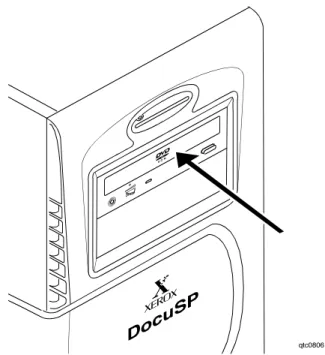
Figure 1-18 DVD/CD-RW drive location on the Sun Blade 2500 or or Sun W1100z
• Back panel: The back panel of the processor has a power
receptacle and outlet, connectors, connector openings, ports, fan, and vent.
Keyboard The keyboard consists of alphanumeric keys similar to a typewriter, symbols and special character keys, an extended character set, and function keys. The keyboard is one of your main methods of communicating with the printer. You can use the keyboard to make selections, and to enter commands that control
functions such as requesting sample prints, or shutting down the system.
Mouse The mouse is another main method of communicating with the printer.
Display monitor The LCD monitor allows you to interact with the printer and to monitor its interaction with the various components. During a print job, printer error messages may display to notify you of any unexpected conditions.
Optional processor components
The controller may be configured with any of the following optional components:
• Connectivity board to enable Token Ring
• Channel interface board for channel connection to a host for online LCDS printing
• One SCSI board to connect to an external tape drive • Creator-3D series 3 graphics board (may replace the video
graphics board delivered with the controller)
External components and options
The following components are external to the processor. The controller stand contains sections that may hold these
components.
• Quarter-inch cartridge (QIC) tape drive • 36-track cartridge tape drive (optional) • External 36 GB hard disk drive (optional)
NOTE: This additional drive is standard equipment on systems with the NPS/IPS extension.
Controller stand
The controller is provided with a special stand that holds all its standard components. In addition to the processor, keyboard with the mouse, and the quarter-inch cartridge tape drive, the stand can accommodate the optional 36-track tape drive and one external hard disk drive (required for the NPS/IPS Extension option).
Online and offline interfaces
The Xerox DocuPrint 100/115/135/155/180 EPS may be
configured for either the online interface, the offline interface, or both.
Online interface The online (channel-attached) interface receives input directly from any environment that supports the IBM 3211 and 4245 host systems.
Offline interface The Xerox DocuPrint 100/115/135/155/180 EPS supports three types of peripheral devices from which you can import resource files such as forms, fonts, and JSLs, and receive print data from tape. These devices are called “peripheral” because they handle media external to the system disk.
The following drives are supported: • 26-track cartridge tape drive (QIC) • 9-track reel tape drives
• 36-track cartridge tape drives
Moving the controller
To ensure consistent performance and avoid any damage to equipment, follow these rules for placing the components of the workstation controller:
• Use the controller stand that comes with your printing system equipment.
• Keep the processor in an upright, vertical position as illustrated below.
• Allow at least 6 inches / 152 mm of unobstructed space at the front and rear of the processor, so the fan and vents are not blocked.
1. Vents in front of processor 2. Vents in back of processor
Figure 1-20 Sun Blade 2500 and Sun W1100z common fan and vent locations to keep clear
1. Vents in front of processor 2. Vents in back of processor
CAUTION: Do not place the monitor on top of the processor. Do
not block any fan or vent on the front, sides, or rear of the processor.
Do not:
• Do not place the monitor and processor on a desk or table top. • Do not place the monitor on top of the processor.
• Do not allow any piece of equipment to blow warm air into the air intake vents of the processor.
• Do not place the processor on its side, or in any other position but the upright, vertical position achieved by using the
controller stand.
Tape drives overview
The DocuPrint 100/115/135/155/180 EPS supports several types of tape drives that may be used to load resources (forms, fonts, etc.) or to submit offline LCDS print jobs.
The 26-track cartridge tape drive, provided with your Xerox DocuPrint 100/115/135/155/180 EPS, can be used only to import resources to the system disk. 9-track and 36-track tape drives can be used to submit print jobs to the DocuPrint EPS, or load
resources.
The DocuSP Tape Client software enables transmission of data from a cartridge or open reel tape to the DocuPrint EPS controller via the Socket gateway.
26-track cartridge tape drive (QIC) (for resource loading only)
The 4 GB external SCSI quarter inch cartridge (QIC) tape drive is an external device provided with the Xerox DocuPrint 100/115/ 135/155/180 EPS. The cartridge tape drive connects to the controller through the SCSI port on the processor back panel. Like the diskette and DVD drives, this tape drive is not an input source for print jobs or for any other data or application. You can use it to load resource files, and the service representative uses it to load system maintenance files or to save diagnostic
information.
Figure 1-21 26-track cartridge tape drive (QIC)
36-track cartridge tape drive
An 18/36-track cartridge tape drive is an option. You can use this drive to load resources and to submit offline LCDS print jobs.
Figure 1-22 18/36-track cartridge tape drive
Peripheral cabinet (9-track and
18/36-track tape drives)
Some Xerox customers may already have a peripheral cabinet that houses a 9-track magnetic and an 18/36-track cartridge tape drive. The DP EPS supports existing peripheral cabinets, but they are not available with new systems. In addition, if a peripheral cabinet has either of the following 18-track tape drives, they are not supported:
• STK 4220 MOD 1 tape drive • STK 4220 MOD 2 tape drive
Figure 1-23 Peripheral cabinet 1. 9-track magnetic tape drive 2. 18/36-track cartridge tape drive
Paper sizing and print speed
The printer paper trays have edge guide sensors that detect paper length and width. The system selects correct paper trays for the print job based on the paper size specified in the job, as follows:
• If an exact match is found, the print job continues.
• If an exact match is not found, the programmer can specify in the job for the printer to do one of the following:
– Stop printing the job and print an error sheet. – Print the data on an oversized sheet.
If you encounter any problems related to paper sizing, contact your lead operator or Xerox service representative.
Long and short edge feeding
To feed through the printer, the leading edge of the paper must be at least 10 inches long. Therefore, the following standard sizes of paper must be loaded so that sheets feed long edge first:
• 7 by 10 inch • B5 • A4 • US Letter • B4 • US Legal
The following papers, which have long edges greater than 14.33 inches / 364 mm must feed short edge first:
• A3
• US Ledger or US Tabloid
NOTE: JIS B4 can be fed either long edge or short edge first.
Paper width and throughput speed (LCDS printing only)
The width of the paper you use for your LCDS print job is directly related to the rate at which the printer can print the job. The rate at which a job prints is called the “throughput speed” and is
measured in pages per minute (ppm).
NOTE: “Pages per minute” actually means “impressions per minute,” referring to one side of a printed sheet.
A pitch is the amount of time the printer takes to image a page on the photoreceptor belt. The term “pitch mode” refers to the number of pitches that can occur during one complete photoreceptor revolution. The pitch mode in which a specific job prints is based on the paper size used for that job.
The following table lists the pitch mode boundary values, paper widths, and related printing speeds for the system. The chart
shows that the shorter the paper width, the higher the pitch mode and the faster the throughput speed (higher page per minute rate).
Table 1-5 Throughput data for DP100
Table 1-6 Throughput data for DP115
Table 1-7 Throughput data for 135
Table 1-8 Throughput data for 155
Pitch Paper width Speed
5 7 to 12.12 in / 178 to 308 mm 100 ppm 4 12.12 to 15.31 in / 308 to 389
mm
77 ppm
3 15.31 to 17 in / 389 to 432 mm 58 ppm
Pitch Paper width Speed
6 7 to 10.19 in / 178 to 259 mm 116 ppm 5 10.19 to 12.12 in / 259 to 308 mm 96 ppm 4 12.12 to 15.31 in / 308 to 389 mm 77 ppm 3 15.31 to 17 in / 389 to 432 mm 58 ppm
Pitch Paper width Speed
8 7 to 7.4 in / 178 to 188 mm 154 ppm 7 7.4 to 9.01 in / 188 to 229 mm 135 ppm 6 9.01 to 10.19 in / 229 to 259 mm 116 ppm 5 10.19 to 12.12 in / 259 to 308 mm 96 ppm 4 12.12 to 15.31 in / 308 to 389 mm 77 ppm 3 15.31 to 17 in / 389 to 432 mm 58 ppm
Pitch Paper width Speed
6 7 to 10.19 in / 178 to 259 mm 154 ppm 5 10.19 to 12.12 in / 259 to 308 mm 128 ppm 4 12.12 to 15.31 in / 308 to 389 mm 103 ppm 3 15.31 to 17 in / 389 to 432 mm 77 ppm
Table 1-9 Throughput data for DP180
Each time a job requires a different paper size that changes across a pitch boundary, the system performs a time-consuming xerographic quality adjustment. When the printing speed of an LCDS job appears to degrade due to the use of mixed stock sizes, the following actions may improve the performance:
• You can optimize throughput by double clicking on a job in Job Manager or double clicking on a queue in Queue Manager and selecting Properties. The Output tab has a Mixed Stock Size Job window where you can select Optimize throughput. You must also enter the width of the widest paper in inches or millimeters for the job.
• The job programmer may be able to improve the speed by using the LCDS PDL command OUTPUT TMODE in the JSL to run the print job in a lower pitch mode. Refer to the
OUTPUT TMODE parameter in the Xerox Document Services Platform Using LCDS Print Description Language for
information on using this command.
• Similarly, if the system cycles down frequently because your external finishing equipment has a slower throughput rate than the printing system, the OUTPUT TMODE command can be used to lower the pitch mode to match the speed of the finishing equipment. This can improve overall throughput by avoiding time-consuming cycle downs.
NOTE: Pitch mode changes are supported only for LCDS printing.
Paper size and pitch mode minimum and maximum
The illustrations in this section show the pitch modes in which you can operate, with the smallest and largest size papers supported by the printing system.
Pitch Paper width Speed
8 7 to 7.4 in / 178 to 188 mm 206 ppm 7 7.4 to 9.01 in / 188 to 229 mm 180 ppm 6 9.01 to 10.19 in / 229 to 259 mm 154 ppm 5 10.19 to 12.12 in / 259 to 308 mm 128 ppm 4 12.12 to 15.31 in / 308 to 389 mm 103 ppm 3 15.31 to 17 in / 389 to 432 mm 77 ppm
Using small paper sizes in 8 pitch mode
Printing in 8 pitch mode provides the highest throughput speed available (up to 206 ppm). However, keep the following in mind when you select the paper you want to use for this mode: • Paper sizes smaller than 8 inches / 203 mm in width are
supported only when the optional 7 inch paper kit is installed on the printer.
• The leading edge of any paper used in the printer cannot be less than 10 inches / 254 mm long.
The following figure illustrates the maximum and minimum paper sizes supported in 8 pitch mode.
Figure 1-24 8 pitch mode paper sizes
1. Maximum paper size for 8 pitch mode 2. Minimum paper size for 8 pitch mode 3. Travel direction of sheets out of paper tray
Using large paper sizes in 3 pitch mode
Large paper sizes with widths of 15.31 to 17 inches / 389 to 432 mm are supported only in 3 pitch mode and must feed short edge first. These paper sizes slow down the throughput speed.
Therefore, a short edge feed job takes longer to print than a long edge feed job.
NOTE: The system can support 14 by 17 inch / 356 by 432 mm, 20 pound or 80 gsm paper stock in 3 pitch mode. However, printing performance is not guaranteed for all types of paper of this size. Heavy (110 pound / 200 gsm) and light (16 pound / 60 gsm) weight papers can cause jams throughout the system, and are not recommended.
The following figure illustrates the maximum and minimum paper sizes supported in 3 pitch mode.
Figure 1-25 3 pitch mode paper sizes
1. Maximum paper size for 3 pitch mode 2. Minimum paper size for 3 pitch mode 3. Travel direction of sheets out of paper tray
Feed direction for standard paper sizes
Currently, 14.33 inches / 364 mm is the maximum paper length for which the system supports long edge feeding (5 to 8 pitch mode). Any papers with long edges greater than this (such as 11 by 17 inch / 279 by 432 mm paper) must be loaded for short edge feeding (3 or 4 pitch mode).
The following figures show how some of the standard paper sizes feed through the printer in various pitch modes.
European papers
Figure 1-27 A3 (297 by 420 mm) paper feeding (short edge feed)
US papers
Figure 1-28 US Letter (8.5 by 11 inch) paper feeding (long edge feed)
Figure 1-29 US Ledger or US Tabloid (11 by 17 inch) paper feeding (short edge feed)
B4 papers There are two versions of B4 paper: European (ISO B4: 9.84 by 13.89 inches / 250 by 353 mm) and Japanese (JIS B4: 14.33 by 10.12 inches / 364 by 257 mm). European B4 feeds long edge first, while JIS B4 may feed either long edge or short edge first.
Figure 1-30 B4 (250 by 353 mm) paper feeding (long edge feed)
Figure 1-31 JIS B4 (257 by 364 mm) paper feeding (may be long or short edge feed)
2
Managing the printer
This chapter describes the operator tasks that are related to printing and print quality.
Controlling the printer
You can perform the following tasks on the DocuSP Print Services window.
You can also select them from the Options pull-down menu on the Printer Manager window.
NOTE: Where available, the printer control console enables you to control certain functions of the printer, such as stopping printing and continuing an interrupted job, without returning to the
controller.
Interrupting printing
Click the red [Pause Printing] icon.
Resuming printing
Click the green [Resume Printing] icon.
Powering on the printer
Select [Printer On] from the Printer menu.
Powering off the printer
1. Select [Printer Off] from the Printer menu. 2. Click [Yes] on the confirmation window.
Powering off the printer immediately
1. Select [Immediate Printer Off] from the Printer menu. 2. Click [Yes] on the confirmation window.
Adjusting the registration transport roll levers for heavy paper
When you use paper that is heavier than 24 pounds/90 gsm, you must adjust the registration transport roll levers, which are located behind areas 2 and 4.
1. Open the right and left doors of the printer. 2. For each lever:
a. Pull the lever toward you.
b. While holding the lever toward you, turn it to the left.
Figure 2-1 Turning the registration transport roll levers
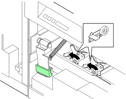
For systems with small paper (7 by 10-inch/178 by 254 mm) enablement:
Systems with this option have three levers. To process heavy papers, turn the levers as shown in the following figure.
Figure 2-2 Three levers in systems with small paper enablement
NOTE: Use the same pressure setting for all levers.
When the job is complete, return the levers to their normal positions.
NOTE: Positioning may be affected by machine tolerance, the paper supplier, or job type (for example, duplex).
Loading paper
Your printer may have up to six feeder trays: two processor trays (trays 1 and 2) and two to four high-capacity trays (trays 3 through 6). Up to six different stocks may be used within a print job, including oversized cover stock or tabs.
• You can unlock, pull out, and load any tray from which paper is not being fed, without interrupting printing.
• If you open a tray that is in use, feeding switches to a backup tray. If no tray is available, printing stops.
• The printer stops feeding paper from any tray when a ¼-inch/6 mm stack remains in the tray.
1. Unlock the tray that you want to load, using one of the
following methods:
• On the printer: Press the Tray Unlock button on the front
of the tray.
Turn to the right
Turn to the right Turn to the left
Figure 2-3 Tray Unlock button on feeder
• At the display monitor: On the Printer Manager window,
Paper Trays tab, right click the tray name. From the properties pop-up menu, select [Tray Unlock].
NOTE: If the printer stops due to insufficient paper in a tray, the system unlocks the tray.
2. When the green Ready to Open indicator lights, pull the feeder
tray out until it stops.
Figure 2-4 Ready to Open indicator
3. Place the paper in the tray, following the instructions on the
l