Please cite this article as: B. Jafari, H. Khatamnejad, M. H. Shahavi, D. D. Ganji, The Simulation of the Dual Fuel Combustion of the Direct Injection Engine with Variable Natural Gas Premixed Ratio, International Journal of Engineering (IJE), IJE TRANSACTIONS C: Aspects Vol. 32, No. 9, (September 2019) 1327-1336
International Journal of Engineering
J o u r n a l H o m e p a g e : w w w . i j e . i rSimulation of Dual Fuel Combustion of Direct Injection Engine with Variable Natural
Gas Premixed Ratio
B. Jafari*a, H. Khatamnejadb, M. H. Shahavia, D. D. Ganjic
a Faculty of Engineering Modern Technologies, Amol University of Special Modern Technologies (AUSMT), Amol, Iran b Mechanical Engineering Department, Urmia University, Urmia, Iran
c Department of Mechanical Engineering, Babol Noshirvani University of Technology, Babol, Iran
P A P E R I N F O
Paper history: Received 23 July 2019
Received in revised form 13 August 2019 Accepted 12 September 2019
Keywords: CFD Simulation Double Injection Gas Percentage Natural Gas Diesel Fuel
A B S T R A C T
Nowadays, the major challenge of diesel engines development is simultaneous nitrogen oxides and soot emissions reduction without the thermal efficiency drop. Hence, different combustion concepts should be investigated to reach optimum emission and performance conditions in diesel engines without expensive aftertreatment systems. This paper presents the results of a study on a dual fuel (DF) engine including natural gas and diesel fuel in view of combustion and emissions parameters. The current investigation also supports by 3D-CFD simulation coupled with the chemical kinetics mechanism for detailed investigation. Based on the results, increasing the premixed ratio of natural gas from 50% to 90% causes the combustion shifts toward the expansion stroke. Therefore, the in-cylinder pressure and combustion efficiency decreases. In 90% premixed ratio of natural gas, the non-combustion condition can be observed. This phenomena leads to extremely increase in HC and CO emissions.
doi: 10.5829/ije.2019.32.09c.14
NOMENCLATURE
HRR Heat release rate (J/CAD) CFD computational fluid dynamics
ITE Combustion efficiency index (%) EGR exhaust gas recirculation
P Pressure (Pa) EVO exhaust valve opening
Qin Input heat (J) HTHR high temperature heat release
V Volume (m3) IVC intake valve closing
Greek Symbols KH-RT Kelvin Helmholtz-Rayleigh Taylor
γ Specific heat ratio (-) LTC low temperature combustion
Abbreviations LTHR low temperature heat release
BTDC before top dead center NOx nitrogen oxides
CA10 start of combustion RCCI reactivity controlled compression ignition
CA50 main combustion phase RI ringing intensity
CA90 end of combustion SFC specific fuel consumption
CAD crank angle degrees UHC unburnt hydrocarbon
1. INTRODUCTION1
Nowadays, the major challenge of diesel engines development is simultaneous nitrogen oxides and soot emissions reduction without the thermal efficiency drop.
*Corresponding Author Email: [email protected] (B. Jafari)
combustion in the locally fuel rich zones. Therefore, the homogeneous mixing of fuel and air prior to the combustion results in more reduction of the soot emission [4, 5]. Hence, extensive studies have been done in recent years on the application of strategies to reduce the combustion temperature of the compression ignition engines. These strategies are commonly classified as low temperature combustion (LTC) technologies. In most LTC strategies, combustion temperature is kept low through the reduction of locally fuel rich zones which are the main contributors to the emissions formation and combustion process. This condition is generally happened in the premixed fuel-air mixture. One of the first experimental studies is done by Selim [4, 5], in which the effect of the engine speed and load variation on the combustion noise of the conventional dual fuel and diesel engines were studied. The test results revealed that the pressure rise rate (the combustion noise) slightly increases with the engine load for the diesel engine; however, considerable increase is seen for the dual fuel engine. The pressure rise rate in the diesel mode is in the range of 4 bars per crank angle degrees (CAD) and it is almost constant. For the dual fuel mode, this parameter ranges from 4 in low loads to 15.5 bars per CAD in higher loads. Furthermore, the results indicate that the pressure rise rate generally reduces with the engine speed for both combustion modes. Krishnan et al. [6] tested different pilot injection timings in a one cylinder diesel engine to find the conditions for less NOx emission and higher thermal efficiency in DF engines. The tests were carried out in full load and the engine speed and the amount of pilot fuel is kept constant. Advancing the injection timing results in an increase in thermal efficiency from 35 to nearly 43%. However, the NOx formation is much higher for the timing of the maximum efficiency. As a general conclusion, it is recommended to advance the pilot fuel injection timing to reduce the NOx formation and maintain the least reduction in the thermal efficiency. Yang et al. [7] studied the influence of the start of diesel fuel injection, start of the natural gas injection and the injection pressure on the emission characteristics and combustion at low load in a DF engine converted from the base diesel engine being equipped with the common rail system. The results indicate that retarding the natural gas injection increases the in-cylinder pressure and the heat release rate (HRR). This is because the delay in the start of natural gas injection increases the fuel-air stratification in the combustion chamber resulting in an improvement in the flame propagation in the cylinder; however, this natural gas injection delay does not have profound effect on engine-out emissions. Moreover, the effect of two diesel injection timings on the emission characteristics and combustion of engine is investigated. Advancing the injection timing from 5 CAD BTDC to 17 CAD BTDC, improves performance and considerably reduces the carbon monoxide and UHC emissions; while
compression stroke forms a partially premixed reactive charge being the combustion initiator.
Regarding the literature survey, most of the RCCI studies are carried out using diesel and petrol fuels and few studies are done on the RCCI combustion of the natural gas and diesel. Furthermore, most of the studies of the RCCI combustion of the natural gas and diesel are experimental studies at mid to high engine loads. Therefore, it is necessary to investigate the RCCI low temperature combustion of natural gas and diesel at part to low loads. In this regard, the CFD simulation using chemical kinetics mechanism is very useful to better understand the characteristics of the RCCI combustion of natural gas and diesel and also the effect of different parameters on the control of in-cylinder charge reactivity.
2. RESEARCH METHODOLOGY
The simulation of internal combustion engine performance deals with different fields of science especially the mechanical engineering. The different aspects of interest may include fluid mechanics, heat transfer, turbulence, numerical calculations, combustion and thermochemistry. The prediction of the details of the flow field in IC engines and the combustion and heat transfer processes is possible by the numerical solution of the conservation equations. The first step in the numerical solution is the creation of a model to describe the processes. To build the model of a process, it is necessary to split it into a set of distinct processes and change the problem to some minor problems. Thereupon, these minor problems should be defined physically and their mathematical formulation should be presented. The simulation models present the combustion process and/or the chemical reactions in the exhaust gas according to the complexity level of the models. The features such as heat and mass transfer and combustion chemistry can be studied and the effective parameters can be correctly determined. In general, the combustion simulation in IC engines can be divided into three categories based on the considered spatial variations [12]:
1. Zero-dimensional models (single-zone
thermodynamic models)
2. Quasi-dimensional models (multi-zone
thermodynamic models)
3. Multi-dimensional models (CFD models)
Multi-dimensional combustion simulation methods which are often called CFD models, are based on the laws of physics and chemistry (simplified by some assumptions) using the experimental results. In this model, a set of momentum, mass, chemical species and energy conservation equations are solved numerically as partial differential equations using appropriate initial and boundary conditions. Moreover, sub-models for
turbulence, chemical processes, boundary layer, etc. are incorporated in this kind of modeling. The most common CFD combustion models which are being used extensively by the researchers at present are Kiva, Star CD and Fire software.
In the present study, the Fire software which is a modern CFD software and has the potential to well simulate the internal combustion engines is used. Using this software, it is possible to couple the tridimensional CFD model and chemical kinetics for accurate prediction of the start of combustion, burn duration, emissions, output power and for correct estimation of the in-cylinder pressure and temperature trace. The simulation of the fuel spray is to determine the mechanisms governing the breakup or separation of large droplets into smaller droplets; finally, evaporation and mixing with the gaseous phase. To date, numerous studies are conducted in this area and many models are presented. In this study, the combination model of Kelvin Helmholtz-Rayleigh Taylor (KH-RT) which is one of the most complete and up-to-date models is used to describe the fuel droplets breakup [13]. In this model, Kelvin Helmholtz surface waves and Rayleigh Taylor turbulence are combined to describe the droplets breakup. The HRR is calculated based on the following model proposed by Krieger and Borman. This model, which is based on the thermodynamic first law, is widely used in the literature for combustion analysis [14].
1 HRR=
1 1
dp dV
V P
d d
− + − (1)
Here, γ is the ratio of specific heats; P and V are instantaneous cylinder pressure and volume, respectively; and θ is the crank angle degrees. The HRR calculation is carried out in the closed cycle from intake valve closing (IVC) to exhaust valve opening (EVO) with constant mass.
In the partially premixed dual fuel combustion, where the major part of the energy is provided from the premixed low-reactive fuel, one of effective factors to control the combustion is the thermo-kinetic reactions which are dependent on the in-cylinder charge properties [15]. Therefore, the chemical kinetics of the fuel is one of important parameters to determine the combustion and emission characteristic. Hence, in the present study, the tridimensional CFD model of the Fire is coupled with Chemkin to solve the chemical kinetics mechanism.
3. MODEL DESCRIPTION AND VALIDATION WITH EXPERIMENTS
TABLE 1. Technical specifications of the engine
6-cylinder direct injection
Engine type
126 mm
Cylinder bore
1500 rpm
Engine speed
High pressure common rail
Diesel fuel injection system
8
Number of injector holes
16.7
Compression ratio
12.4 l
Displacement volume
30 CAD after bottom dead center
IVC
36 CAD BTDC
EVO
The engine is equipped with high pressure common rail fuel injection system and engine management system. The diesel fuel injection system can inject the fuel with a constant pressure up to 2000 bars using 8-hole injectors. 8 injection valves are added to the downstream of the air path after the intercooler in the air manifold for natural gas admission to the intake air. Due to the use of the 8-hole diesel fuel injector and the created symmetry, only a 45-degree tridimensional section of the combustion chamber shown in Figure 1a is modeled in the present study.
Based on the simulation results of the different mesh sizes and the runtime, the mesh size providing a whole mesh number of 20,350 cells at top dead center is selected for the simulation. Figure 1b indicates grid dependency assessment of CFD model for one case.
Figure 1a. The simulated combustion chamber at TDC
Figure 1b. The grid dependency analysis of CFD model
In this work, the RNG k-e model was used as turbulence model. Diesel injection process is simulated by the standard Droplet Discrete Model. The Kelvin-Helmholtz Rayleigh-Taylor (KH-RT) model was selected to represent spray breakup. In this model, Kelvin-Helmholtz (KH) surface waves and Rayleigh-Taylor (RT) disturbances should be in continuous competition of breaking up the droplets. The Dukowicz model was used for modeling heat-up and evaporation of droplets. In this model, droplets were supposed to evaporate in a non-condensable gas consisting of two-component system in the gas phase (vapor and the non-condensable gas). Wall heat flux calculation was simulated with FIRE standard wall function model for which accounts for the variations of gas density and turbulent Prandtl number in the boundary layer.
As mentioned before, a multi-dimensional CFD model coupled with chemical kinetic mechanism was developed in the present study. All related processes in flow filed of defined domain can be calculated by developed CFD model. The FIRE internal chemistry interpreter detailed chemistry solver is used in this study to include chemistry in combustion simulations, based on the same theory, which is implemented within CHEMKIN. The FIRE internal chemistry interpreter calculates the reaction rates for each elementary reaction while the CFD solves the transport equations. In this study, a reduced dual-fuel chemical mechanism for n-heptane and methane composed of 50 species and 201 reactions is used for detailed combustion chemistry calculations during engine cycle. It should be noted that the natural gas has been modeled as pure methane in current study because a typical natural gas contains 92% methane by volume, and similar properties. Also n-heptane used as a surrogate for diesel fuel. The NOx formation chemistry is represented by four species and 12 reactions, which is a reduced version of the GRI NOx mechanism based on extended Zeldovich mechanism.
To test the engine at varying load and speed based on the procedure, the engine is installed in the test cell with different connections such as water, oil, air and exhaust. To apply load on the engine a 560 kW ABB Innovasys HS001779 dynamometer is used. The amount of natural gas and diesel fuels are measured with a Micromotion CMF025M319NRAUEZZ mass flow meter. The air mass flow is measured with ABB 14241-7962637. The exhaust gas content is analyzed with the Horiba MEXA 7500 DEGR 5-gas analyzer. The soot emission is measured with AVL 415S. The in-cylinder pressure is measured with Kistler 6061B pressure transducer and the results are recorded on a CAD basis. Figure 2 shown the schematic diagram of the engine test cell. The uncertainty values for the engine parameters used in this study are presented in Table 2.
0 28 56 84 112 140
320 336 352 368 384 400
Cyli
n
d
er
p
re
ss
u
re
(
b
ar)
Crank Angle (Degree)
Experimental
Figure 2. The schematic diagram of the test room
TABLE 2. Experimental uncertainty
Uncertainty (%) Parameter <2 Temperature <2 Pressure <1 Engine speed <1 Fuel flow rate
<1 Air flow rate
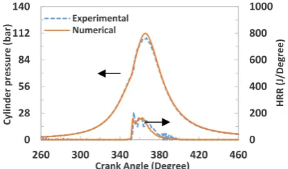
Two test cases were selected for the validation of the DF engine combustion simulation results. Table 2 presented the operating conditions for the two cases. Figures 3a and 3b illustrate the comparison of the simulation and the experimental results of the in-cylinder pressure traces for the two test cases summarized in Table 3.
It is seen that the tridimensional model can accurately predict the in-cylinder pressure in compression and expansion strokes and the peak combustion pressure is calculated with negligible error. The main contributors to this negligible error may include: the uncertainty in the estimation of the temperature at IVC and uncertainty in the estimation of the residual gas mass in experiments; taking the piston and wall temperatures constant and
Figure 3a. The comparison of the simulation and
experimental results of the in-cylinder pressure and HRR for test case 1
Figure 3b. The comparison of the simulation and
experimental results of the HRR and in-cylinder pressure for test case 2
TABLE 3. Engine operating conditions of the test cases for the
validation Case #2 Case #1 Parameters 2.28 2.58
Natural gas mass flow rate to the cylinder (kg/h)
0.70 0.73
Diesel fuel mass flow rate to the cylinder (kg/h) 36 36 EGR (%) 384 385
Temperature at IVC (K)
1.80 1.87
Pressure at IVC (bar)
30 18
Start of diesel fuel injection (CAD BTDC)
uniform in simulations. Hense it can be concluded that the CFD/chemical kinetics model can well predict the in-cylinder pressure.
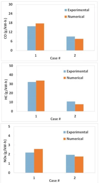
The validation and comparison of the simulation and the experimental results of the engine-out emissions are demonstrated in Figure 4.
The simulation results are the amount of UHC, carbon monoxide and NOx at EVO. The variation trend of the emissions are consistent in simulation and experimental results and the amount of the emissions are well predicted by the simulation. The main important reasons of the differences between simulation and experimental emission results may include: simplification of the EGR composition; uncertainties in the estimation of the combustion chamber wall temperatures due to the unavailable experimental measurements of these temperatures; and considering the test fuels as methane and normal heptane.
4. RESULTS AND DISCUSSION
According to the research targets, test case 2 of Table 2 is selected as the base operating condition for the rest of the study on the dual fuel engine at part loads. Figures 5
Dy n a m ome ter Pressure transducer Exhaust gas analyzer NOx, HC, CO
Air flowmeter CNG flowmeter Regulator CNG mixer EG R co ol e r Diesel flowmeter Fu e l i
n Fue
l ou t Charge air cooler Turboch arge r Engine 0 200 400 600 800 1000 0 28 56 84 112 140
260 300 340 380 420 460
HRR ( J/ Degr ee ) C yl in d er p re ss u re ( b ar )
Crank Angle (Degree) Experimental Numerical 0 200 400 600 800 1000 0 28 56 84 112 140
260 300 340 380 420 460
HRR (J /De gree ) C yl in d er p re ss u re ( b ar )
Crank Angle (Degree) Experimental
and 6 demonstrate the results of in-cylinder pressure trace and HRR at different natural gas premixed ratios.
Figure 4. The comparison of the simulation and
experimental results of the main engine-out emissions according to table 2
Figure 5. The comparison of in-cylinder pressure traces at
different natural gas premixed ratios
Figure 6. The comparison of HRR at different natural gas premixed ratios
It is seen that although the total energy content input to the combustion chamber is kept constant, the condition in which the premixed ratio is 50% leads to the maximum peak pressure. Increasing the natural gas percentage from 50 to 80% reduces the peak pressure from 141 to 118 bars. The reason can be sought by considering the HRR curves and the increase of the HRR in lower premixed ratios. the results shown the HRR curve has two peaks: the first phase is due to the occurrence of the cool flame reactions and considered as the low temperature heat release (LTHR). This phase with lower rate is due to the premixed combustion of the diesel fuel and is increased by increasing the ratio of injection of the high-reactive diesel fuel as can be seen in Figure 6. The second phase of the combustion is considered as the high temperature heat release (HTHR) having higher rate and is influenced by the combustion of the premixed natural gas [16]. Based on the results, increasing the premixed ratio of natural gas to 90% reduces LTHR and HTHR significantly which is an indicator of the occurrence of partial/misfire burning and flame quenching in the cylinder. Combustion phasing specifications such as start of combustion (CA10), the occurrence of the main combustion phase (CA50) and the end of combustion (CA90) are the main specifications in the investigation of the combustion details in IC engines. The variations of these parameters are demonstrated in Figure 7 in order to study the natural gas ratio influence on the details of combustion and HRR.
It is seen that the increase in natural gas premixed ratio delays CA10 and the timing of the main combustion phase. This is due to increase in natural gas ratio, being a fuel with high auto-ignition temperature and low reactivity, reduces the reactivity of the in-cylinder charge and as a result delays the start of and the main combustion [17, 18]. Furthermore, the reduction in premixed ratio at fixed operating conditions similar to the base case, results in the reduction of the burn duration and the occurrence of a fast combustion. Therefore, the main combustion phase can be controlled by the adjustment of the ratio of diesel fuel to natural gas in a DF engine. The dependence
0 32 64 96 128 160
320 340 360 380 400 420
Cyli
n
d
er
p
re
ss
u
re
(
b
ar)
Crank Angle (Degree)
PR=50% PR=60% PR=70% PR=80% (Base) PR=90%
0 120 240 360 480 600
335 345 355 365 375 385
HRR
(
J/D
eg
re
e)
Crank Angle (Degree)
PR=50% PR=60% PR=70% PR=80% (Base) PR=90%
LTHR
↓
Figure 7. The comparison of combustion phasing (CA10, CA50 and CA90) at different natural gas premixed ratios
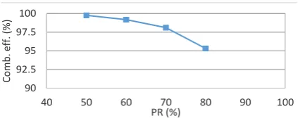
of the combustion phasing on the ratio of the two fuels can be an appropriate control tool for the RCCI combustion comparing with other LTC technologies. Hence, the amount of each fuel should be controlled carefully for the optimum operation of the engine [19, 20]. Figure 8 presents the combustion efficiency index to study the quality of the combustion at different conditions.
The combustion efficiency index is calculated with the correction factor presented in equation (2) in which Qin is the total energy provided by the fuel.
180
180
ITE= 100%
in
Pdv
Q
−
(2)Diesel fuel ratio increase as the fuel with high reactivity and the combustion initiator, the combustion efficiency also increases. This is due to the fast combustion of the natural gas at this condition makes it possible for the flame to propagate well in the in-cylinder lean mixture at
Figure 8. The comparison of combustion efficiency at
different natural gas premixed ratios
part loads. The flame quenching at 90% premixed ratio significantly decreases the combustion efficiency approaching zero. This case is not shown in Figure 8 for better comparison of results. An important issue in the investigation of premixed engines is the determination of the combustion noise and knocking level being a limiting factor in the development of these engines. According to the literature and due to the investigated engine is a turbocharged one, where the intake air pressure is boosted, the pressure rise rate cannot be an appropriate index for determining the knock level of the engine. Therefore, the ringing intensity (RI) index proposed by Eng is considered in this study [21]. In this method, the intensity of the combustion compression waves is determined based on the amplitude and speed of sound. According to the experimental studies, the maximum amount of this index for a non-knocking premixed combustion (such as RCCI) in a heavy diesel engine is determined as 5 MW/m2 [22]. Figure 9 demonstrates the calculated RI at different natural gas premixed ratios.
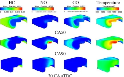
It is seen that RI decreases by increasing the premixed ratio while other operating conditions such as intake air pressure and temperature, start of diesel fuel injection and EGR level. This is because of decrease in the in-cylinder temperature, pressure and combustion rate. A 50% natural gas premixed ratio results in an amount of RI higher than that of determined for non-knocking combustion. Therefore, some operating conditions such as diesel fuel injection timing should be regulated to get the optimum RI. Therefore, in order to operate the engine at 50% natural gas premixed ratio in the test cell, it is required that the engine map be modified for the non-knocking operation. For verifying the variation and distribution of emissions formation at different natural gas premixed ratios, their distribution at different conditions are demonstrated in Figure 10 at CA50 and CA90 timings.
By increasing the natural gas premixed ratio and decreasing the charge reactivity and ignition initiation spots, the combustion is delayed and its rate decreases resulting in a reduction in in-cylinder combustion. Generally, the main reasons for carbon monoxide formation are the reduction in charge temperature, the reduction in oxygen availability and the short reactive charge reaction duration. Therefore, too much reduction
Figure 9. The comparison of ringing intensity at different
natural gas premixed ratios
340 344 348 352 356
40 50 60 70 80 90 100
CA
1
0
(D
egree)
PR (%)
345 351 357 363 369
40 50 60 70 80 90 100
CA
5
0
(D
egree)
PR (%)
351 360 369 378 387
40 50 60 70 80 90 100
CA
9
0
(D
egree)
PR (%)
90 92.5 95 97.5 100
40 50 60 70 80 90 100
Co
m
b
. eff. (%
)
PR (%)
0 2 4 6 8
40 50 60 70 80 90 100
RI (M
W/
m
^2
)
Temperature CO
NO HC
CA50
CA90
30 CA aTDC
Figure 10a. The distribution of temperature and emissions
mass fractions at different timings in the engine cycle at 50% natural gas premixed ratio
Temperature CO
NO HC
CA50
CA90
30 CA aTDC
Figure 10b. The distribution of temperature and emissions
mass fractions at different timings in the engine cycle at 60% natural gas premixed ratio
Temperature CO
NO HC
CA50
CA90
30 CA aTDC
Figure 10c. The distribution of temperature and emissions
mass fractions at different timings in the engine cycle at 70% natural gas premixed ratio
Temperature CO
NO HC
CA50
CA90
30 CA aTDC
Figure 10d. The distribution of temperature and emissions
mass fractions at different timings in the engine cycle at 80% natural gas premixed ratio
Temperature CO
NO HC
CA50
CA90
30 CA aTDC
Figure 10e. The distribution of temperature and emissions
mass fractions at different timings in the engine cycle at 90% natural gas premixed ratio
in the temperature, resulted from 90% substitution of the natural gas, significantly increases carbon monoxide formation due to the significant reduction in its oxidation reaction rate. The main reasons for the formation of UHC are: flame quenching as a result of impingement to a low-temperature wall leading to an unburnt film of mixture on the wall; the compression of the air-fuel mixture in the upper region of the piston compression ring which is away from the flames of the main combustion, therefore remaining in the cylinder without complete oxidation; and the existence of the lean fuel-air mixture which prevents combustion and flame propagation [23, 24]. The reduced natural gas premixed ratio, increases the initial energy content and ignition initiation spots of pilot diesel fuel which is accompanied by increased velocity and turbulence of the diesel fuel spray at higher flow rates and its breakup and atomization. Therefore, the improved combustion by decreased level of natural gas substitution, results in a more complete oxidation of the premixed natural leading to a decrease in the UHC formation especially in the pressure regions and the regions above the compression ring.
5. CONCLUSION
increasing the gaseous fuel (methane) ratio retards the main combustion phase to the expansion stroke and as a result decreases in-cylinder pressure. This is due to decrease in the charge reactivity and the reduction in the formation and decomposition of the intermediate chemical species involved in the combustion like as formaldehyde and hydroxyl which directly influence the methane decomposition and HTHR rate. The improved flame stability and propagation throughout the combustion chamber at lower natural gas substitution levels increases the combustion efficiency. However, the RI index is also increased due to the increased in-cylinder pressure rise rate. Furthermore, basesd on the main combustion phasing, the best performance in terms of specific fuel consumption and thermal efficiency is achieved by 70% natural gas substitution. Moreover, 90% natural gas substitution results in the no-combustion condition.
6. ACKNOWLEDGMENT
This research work was financially supported through a research grant funded by Amol University of Special Modern Technologies (Amol, Iran). Also, the authors are grateful to acknowledge FEV North America Inc. for providing the test data used in correlation the baseline simulation models.
7. REFERENCES
1. Plee, S., Ahmad, T. and Myers, J., "Flame temperature correlation for the effects of exhaust gas recirculation on diesel particulate and nox emissions", SAE Transactions, Vol. 90, No. 4, (1981), 3738-3754.
2. Omidi Kashani, B. and Pirouzpanah, V., "Development of a mathematical model for prediction of pollutants emission in di diesel engines", International Journal of Engineering, Vol. 11, No. 1, (1998), 37-42 .
3 . Kohansal, M., Hosseini, M. and Shahavi, M.H., "Making water in octane nanoemulsion fuel as an environmentally friendly fuel: Effect of water content on droplet size", in The 8th International Chemical Engineering Congress & Exhibition (IChEC 2014), Kish Island, Iran. Vol. 8, (2014) .
4 . Glassman, I., "Soot formation in combustion processes",
Symposium (International) on Combustion, Vol. 22, No. 1, (1989), 295-311 .
5 . Khalilarya, S., Khatamnezhad, H., Jafarmadar, S., Oryani, H. and Pourfallah, M., "Numerical investigation on the effect of injection timing on combustion and emissions in a di diesel engine at lowtemperature combustion conditions", International Journal of Engineering-Transactions B: Applications, Vol. 24, No. 2, (2011), 165-179 .
6 . Krishnan, S.R., Srinivasan, K.K., Singh, S., Bell, S., Midkiff, K., Gong, W., Fiveland, S. and Willi, M., "Strategies for reduced nox emissions in pilot-ignited natural gas engines", Journal of Engineering for Gas Turbines and Power, Vol. 126, No. 3, (2004), 665-671 .
7 . Yang, B., Xi, C., Wei, X., Zeng, K. and Lai, M.-C" ,.Parametric investigation of natural gas port injection and diesel pilot injection
on the combustion and emissions of a turbocharged common rail dual-fuel engine at low load", Applied Energy, Vol. 143, No., (2015), 130-137 .
8 . Lounici, M.S., Loubar, K., Tarabet, L., Balistrou, M., Niculescu, D.-C. and Tazerout, M., "Towards improvement of natural gas-diesel dual fuel mode: An experimental investigation on performance and exhaust emissions", Energy, Vol. 64, No., (2014), 200-211 .
9 . Kusaka, J., Tsuzuki, K . - i., Daisho, Y. and Saito, T., A numerical study on combustion and exhaust gas emissions characteristics of a dual fuel natural gas engine using a multi-dimensional model combined with detailed kinetics. 2002, SAE Technical Paper . 10 . Maghbouli, A., Saray, R.K., Shafee, S. and Ghafouri, J.,
"Numerical study of combustion and emission characteristics of dual-fuel engines using 3d-cfd models coupled with chemical kinetics", Fuel, Vol. 106, No., (2013), 98-105 .
11 . Hockett, A.G., Hampson, G. and Marchese ,A.J., "Natural gas/diesel rcci cfd simulations using multi-component fuel surrogates", International Journal of Powertrains, Vol. 6, No. 1, (2017), 76-108 .
12 . Kuo, K.K.-y., "Principles of combustion", 2nd ed, New Jersey, John Wiley & Sons, (2005), 760 .
13 . Beale, J.C. and Reitz, R.D., "Modeling spray atomization with the kelvin-helmholtz/rayleigh-taylor hybrid model", Atomization and Sprays, Vol. 9, No. 6, (1999), 623-650 .
14 . Zhao, H. and Ladommatos, N., "Engine combustion instrumentation and diagnostics", Warrendale, PA: Society of Automotive Engineers, 2001. 842, (2001) .
15 . Gordon, S. and McBride, B.J., Computer program for calculation of complex chemical equilibrium compositions, rocket performance, incident and reflected shocks, and chapman-jouguet detonations. Interim revision, march 1976. 1976, NASA: USA . 16 . Ebrahimi, M., Najafi, M., Jazayeri, S.A. and Mohammadzadeh,
A.R., "A detail simulation of reactivity controlled compression ignition combustion strategy in a heavy-duty diesel engine run on natural gas/diesel fuel", International Journal of Engine Research, Vol. 19, No. 7, (2018), 774-789 .
17 . Nazemi, M. and Shahbakhti, M., "Modeling and analysis of fuel injection parameters for combustion and performance of an rcci engine ,"Applied Energy, Vol. 165, (2016), 135-150 .
18 . Paykani, A., Kakaee, A.-H., Rahnama, P. and Reitz, R.D., "Effects of diesel injection strategy on natural gas/diesel reactivity controlled compression ignition combustion", Energy, Vol. 90, (2015), 814-826 .
19 . Kokjohn, S., Hanson, R., Splitter, D., Kaddatz, J. and Reitz, R., "Fuel reactivity controlled compression ignition (rcci) combustion in light-and heavy-duty engines", SAE International Journal of Engines, Vol. 4, No. 1, (2011), 360-374 .
20 . Khatamnejad, H., Khalilarya, S., Jafarmadar, S., Mirsalim, M. and Dahodwala, M., "Toward an improvement of natural gas-diesel dual fuel engine operation at part load condition by detail cfd simulation", International Journal of Engineering-TransactionsA: Basics, Vol. 31, No. 7, (2018), 1082-1087 . 21 . Eng, J., Characterization of pressure waves in hcci combustion.
2002, SAE Technical Paper .
22 . Nieman, D.E., Dempsey, A.B. and Reitz, R.D., "Heavy-duty rcci operation using natural gas and diesel", SAE International Journal of Engines, Vol. 5, No. 2, (2012), 270-285 .
23 . Badr, O., Karim, G. and Liu, B., "An examination of the flame spread limits in a dual fuel engine", Applied Thermal Engineering, Vol. 19, No. 10, (1999), 1071-1080 .
Simulation of Dual Fuel Combustion of Direct Injection Engine with Variable Natural
Gas Premixed Ratio
B. Jafaria, H. Khatamnejadb, M. H. Shahavia, D. D. Ganjic
a Faculty of Engineering Modern Technologies, Amol University of Special Modern Technologies (AUSMT), Amol, Iran b Mechanical Engineering Department, Urmia University, Urmia, Iran
c Department of Mechanical Engineering, Babol Noshirvani University of Technology, Babol, Iran
P A P E R I N F O
Paper history: Received 23 July 2019
Received in revised form 13 August 2019 Accepted 12 September 2019
Keywords: CFD Simulation Double Injection Gas Percentage Natural Gas Diesel Fuel
A B S T R A C T
زا .تسا یترارح ۀدزاب شهاک نودب هدود و نژورتین یاهدیسکا نامزمه شهاک لزید یاهروتوم ۀعسوت یلصا شلاچ هزورما
هدافتسا نودب لزید یاهروتوم رد یدیلوت یاه هدنیلاآ نازیم و یدرکلمع طیارش لوصح یارب یقارتحا فلتخم میهافم ورنیا
ب دیاب شزادرپ سپ نارگ یاهمتسیس زا رد .دنوش یسرر
نیا هلاقم جیاتن هعلاطم رب کی یور روتوم تخوس اب هک زوس هناگود
،دنک یم راک یعیبط زاگ و لزید اب
هجوت هب یاهرتماراپ قارتحا و هئارا یگدنیلاآ هدش
هس یزاس هیبش اب اه یسررب نیا .تسا
یدعب
CFD
تبسن شیازفا ،جیاتن هب هجوت اب.تسا هتفرگ ماجنا ،هدش لپوک ییایمیش کیتنیس مزیناکم اب رتقیقد ۀعلاطم یارب هک
زا یزاگ تخوس تخوس 50
% هب 90 % ردنلیس لخاد راشف نیاربانب .دوش یم طاسبنا هلحرم تمس هب قارتحا زاف تکرح ببس
زاگ تخوس تبسن رد .دبای یم شهاک قارتحا ۀدزاب و 90
% هب رجنم هدیدپ نیا .دوش یم هدهاشم قارتحا عوقو مدع طیارش ،
هدنیلاآ دح زا شیب شیازفا یاه
HC
و
CO
.دوش یم doi: 10.5829/ije.2019.32.09c.14