Muhammad DAUHOO, Laurent DUMAS, Pierre GABRIEL and Pauline LAFITTE
A NEW DECOMPOSITION BASIS FOR THE CLASSIFICATION OF
ABERRATIONS OF THE HUMAN EYE
Laurent Dumas
1, Damien Gatinel
2and Jacques Malet
3Abstract. The optical defects of the human eye are analyzed and classified by studying the corre-sponding ocular wavefront. After presenting the orthogonal basis, called the Zernike basis, which is currently used for the wavefront analysis, a new mathematical decomposition basis is built. In this new basis, the phase errors due to the low degree aberrations terms are totally separated from the high order terms, in order to improve the relevance of the clinical interpretation through a better appreciation of the low vs high aberration wavefront components. Various clinical examples (myopia, keratoconus) clearly show the interest of this new basis compared to a diagnosis based on the Zernike decomposition.
R´esum´e. Les d´efaut optiques de l’oeil humain sont analys´es et class´es `a partir des caract´eristiques math´ematiques du front d’onde de l’oeil consid´er´e. Apr`es avoir pr´esent´e la m´ethode actuelle bas´ee sur la d´ecomposition du front d’onde dans la base orthonormale de Zernike ainsi que certaines de ses limitations, on propose ici une nouvelle base de d´ecomposition bas´ee sur une s´eparation stricte des effets de bas degr´e et de haut degr´e. Diff´erents cas cliniques pr´esent´es dans la derni`ere section permettent de mettre en ´evidence l’int´erˆet de cette nouvelle base de d´ecomposition.
1.
Vision and optical aberrations
1.1.
The visual process
Vision is a complex process that can be grossly divided into two steps: an optical step and then a neural one. After being refracted by the cornea, part of the light which enters into the eye passes through the pupil, whose diameter is variable. This light then passes through the crystalline lens, acting as a focusing element with a curvature that can be modified by the action of ciliary muscles in order to form a sharp image on the retina of objects located at various distances from the eye (accommodation principle). The visual information is then transmitted to the brain via the optic nerve.
In the eye, the light travels through various media with different index values. For a monochromatic light wave, its wavelength is decreased in denser media (i.e. with higher refractive indices) whereas its frequency is unchanged. The optical path length is defined as the number of wavelengths between the light source and the image plane. It is equal to the product of the geometric length of the path which light follows, and the index of refraction of the medium through which it propagates. If this distance is the same for all the light rays emitted by a single point source, the quality of the obtained image is optimal, as the latter is created by focusing light waves with a maximal constructive interference at the plane of observation.
1 Laboratoire de Math´ematiques de Versailles, UVSQ, CNRS, Universit´e Paris-Saclay, 78035 Versailles, France. 2 Department of Anterior Segment and Refractive Surgery, Fondation Rothschild, 75019 Paris, France. 3 PhD, no afiliation.
c
EDP Sciences, SMAI 2018
A wavefront is a surface over which an optical wave has a constant phase. In 3D space, a point source emits wavefronts that are spherical in shape, which propagate radially outward. The center of these wavefronts is the point source. The optical rays are materializing the direction of propagation of the wavefront, and are always perpendicular to the surface of the wavefront at each point [5].
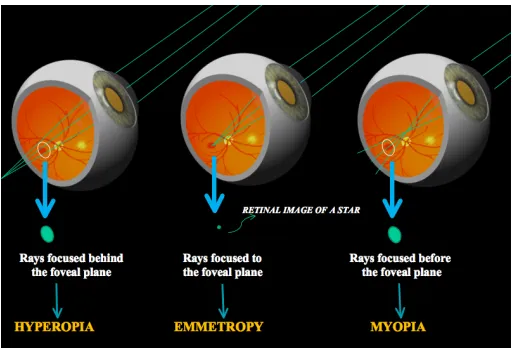
The example of a star in a night sky, can be taken as an elementary light source. Only a small portion of the light waves emitted from the star can be captured by an eye gazing at it. Although the wavefronts produced by the star considered as an elementary point are always concentric spheres in principle, the radii of the spheres are so large that they look like plane waves to a terrestrial observer. It is equivalent to consider that the rays that are striking the eye are all parallel. The successive refraction by the cornea and the crystalline lens make these rays ideally focused to the foveal plane into a single location. Such eye is said to be emmetropic.
Hence, neglecting the effect of diffraction, the ideal retinal image of a light point source is a point. The property of an optical system in which rays of light from a single point converge in a single focal point is called ”stigmatism”. Conversely, if not all these rays are focused in a single point, the image is blurred. In visual optics, this can happen either when the eyeball is too ’long’ (myopia) or too ’short’ (hyperopia), with respect to its focusing length (see figure 1).
Figure 1. Eye vision of a point source (a star for instance).
The point spread function (PSF) describes the response of an imaging system to a point source or point object. The degree of spreading (blurring) of the point object is a measure for the quality of an imaging system. For instance, for a myopic eye, the distance to the retina plane is too long for rays emanating from a source located at infinity. The optical path length increases for rays located further away from the optical axis. The PSF is no longer a point but a blur disc. However, the retinal image formed by a myopic eye can be sharp if the point source is located nearer to the eye. In such situation, the peripheral rays have a longer geometrical path to the fovea than the central rays, which thus ’equalizes’ the optical path lengths along every refracted ray.
1.2.
Measuring the wavefront error
Figure 2 gives an example of a retina image made from monochromatic and parallel rays for two different eyes. On the top of this figure, the eye refractive elements (represented schematically by a single lens) are
Figure 2. The retina image formation. Case of a perfect eye (top) and an eye with defaults (bottom).
perfect in the sense that after refraction by the cornea and the crystalline lens, the envelope of the wavefronts are spherical and the PSF is analogous to a single point (again neglecting the effect of diffraction). On the bottom of the same figure, the eye has optical imperfections, also called high-order aberrations: some peripheral rays are not focalised in the same plane as the paracentral ones. This corresponds to the presence of phase delays or advances with regards to the reference spherical enveloppe of the wavefront of a ”perfect” eye. As a consequence, the PSF is no longer a single point and the retinal image quality degrades. To quantify such aberrations, the wavefront error function is defined as the representation of the phase differences between a ”perfect” wavefront, and the measured wavefront. It is defined on the pupil disc, within which the phase delays and advances are computed.
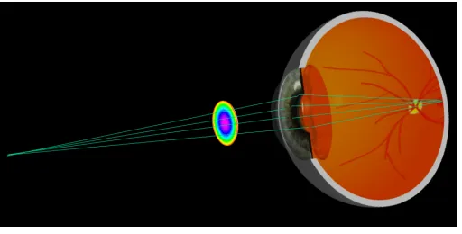
The experimental measurements of ocular wavefronts which are performed in ophtalmology are based on the collection and sampling after reflection on the central retina of a monochromatic light beam (see figure 3) [2, 3]. A wavefront reflecting off the retina becomes deformed as it passes through the eye’s optics, crystalline lens and cornea. The aberrated wavefront emerging from the eye contains information about the optical defects it possesses. Imaging techniques allow to quantify the wavefront error of the measured eye. As an example, the wavefront that is collected outside of the eye after foveal reflection of a myopic eye will possess a spherical geometry, which can be modelled by a quadratic function (see an example of such a wavefront on figure 4).
Figure 4. Example of a collected wavefront for an eye with myopia.
The central shape of the collected wavefront thus allows to predict the refractive correction. The power of the spectacle lenses, corresponding to low-order aberrations, can be predicted with acceptable precision in most clinical situation from the osculating curvature of the wavefront, which is expressed as a quadratic function. The presence of peripheral phase errors, expressed as high-order aberrations, will affect the optical quality of the eye. In low light conditions, the pupil dilates, and the wavefront error of human eyes tends to increase dramatically.
Our understanding of the optical quality of the eye has become more accurate with the ability to precisely measure the lower and higher order wave aberrations using ocular wavefront sensing techniques. However, a deeper mathematical analysis of the wavefront function may be needed to better classify and quantify the origin of the corresponding ocular wavefront aberration.
2.
The mathematical treatment of wavefronts
On a mathematical viewpoint, the eye wavefront can be seen as a real valued function defined on theR2unit
disc, corresponding to the normalized pupil (assumed to be perfectly spherical, see [6]):
D={(x, y)∈R2, x2+y2≤1}
The scalar product between two wavefronts ofC(D,R) is defined with the expression:
< f, g >= 1
π
Z
D
f(x, y)g(x, y)dxdy
In particular, it allows to define the distance from a wavefront to its average, called RMS (Root Mean Square) error:
RM S=||f−p0(f)||D=
1
π
s Z
D
(f(x, y)−p0(f))2dxdy
wherep0(f) =
1
π
Z
D
Denote PDthe set of polynomial functions on D and P
(N)
D the subset ofPD made of polynomials of total
degree lesser than N. A general wavefront can be approximated by its orthogonal projection P(f) on PD(N). The degree (respectively valuation) ofP(f) is then called degree (respectively valuation) of the projection off.
2.1.
The Zernike decomposition basis
The polar coordinates (r, t) ∈ [0,1]×[0,2π[ such that x =rcos(t) et y = rsin(t) are more suited to the geometry of the problem and lead to express the wavefront projection as a trigonometric polynomial. The Gram-Schmidt orthonormalisation principle of the radial part of the canonical basis of trigonometric polynomials lead to the definition of the so-called Zernike polynomials (see the reference paper of Zernike [7]). This family is sorted by radial degree, and for a given degree in increasing order of azimutal frequency. More precisely, the Zernike polynomial Zm
n is given for any integernand anym∈ {−n,−n+ 2, ..., n−2, n} by the expression:
Znm(r, t) =Rn|m|(r)T(m)(t)
whereTm(t) = cos(mt) ifm≥0 andTm(t) = sin(|m|t) ifm <0.
After formal computations, it gives:
Znm=
p
2(n+ 1) X
0≤k≤n−m
2
(−1)k (n−k)!
k! n−2m−k!n+2m−k!
rn−2k cos(mt) if m >0
√
n+ 1 X
0≤k≤n
2
(−1)k (n−k)!
k!n
2 −k
!n
2−k
!
rn−2k if m= 0
p
2(n+ 1) X
0≤k≤n+m
2
(−1)k (n−k)!
k!n−2m−k! n+2m−k!
rn−2k sin(|m|t) if m <0
The integer n is a positive integer called the radial degree, m is a negative or positive integer called the azimutal frequency. Note that the difference betweenn andm is an even number. Hence, there are noZ10 or
Z4−3Zernike polynomials. Note also that whenmis equal to zero, there is no angular dependency and the mode is rotationally symetric.
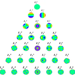
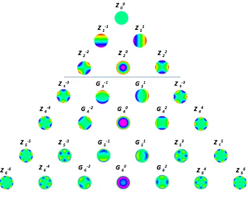
The pyramidal shape of the Zernike decomposition is depicted on figure 5.
In this basis, any wavefront projection has the following expression, called horizontal decomposition:
P(f) =
N
X
n=0
X
m∈In
< f, Znm> Znm
whereIn= (−n+ 2N)∩(n−2N).
The orthogonality of the Zernike basis also allows to compute easily any wavefront moment, as for instance the RMS value:
RM S= v u u t N X n=1 X
m∈In
< f, Zm n >2
2.2.
Interpretation of the optical aberrations in the Zernike basis
The current standard method of describing the ocular wavefront error is based on the use of the Zernike polynomial basis [4]. Each Zernike polynomial can be seen as a particular wavefront error within the eye’s pupil. Some modes, such asZ0
Figure 5. The orthonormal basis of Zernike polynomials
Z4−4) . Table 1 gives the most common interpretation of Zernike polynomials as optical aberrations. Note that the constant polynomialZ0
0 = 1 is called piston.
An the eye that has coma along axis produces a comet-shaped blur on the retina (Coma aberration comes from ”comet” in latin). A blurred image occurs when light from the margin of a lens or mirror with a spherical surface comes to a shorter focus than light from the central portion, hence the name ?spherical aberration?.
Zernike polynomial optical aberration
Z0
0 piston
Z1−1 vertical tilt
Z11 horizontal tilt
Z2−2 bent astigmatism
Z0
2 myopia / hyperopia
Z2
2 horizontal/vertical astigmatism
Z3−3 vertical trefoil
Z3−1 vertical coma
Z31 horizontal coma
Z3−3 horizontal trefoil
Table 1. The first Zernike polynomials and their corresponding eye aberration.
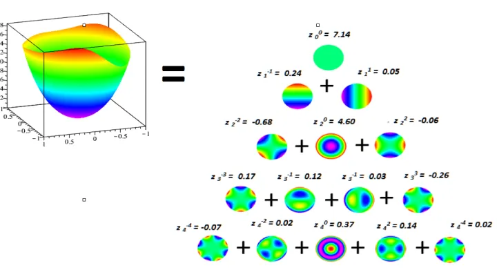
Figure 6. Decomposition of a quasi parabolic wavefront profile in the Zernike basis for a 5
mm pupil diameter.
On this particular case, the global shape is parabolic and is due to a myopia. Firstly, the values of the order 1 coefficients in the Zernike decomposition are surprisingly not negligible (in particular, the value of the vertical tilt coefficient z1−1 is large). This would indicate that there exists a predominantly vertical deviation angle from the main propagation direction of the wavefront, whereas the measurements are routinely performed in a rectilinear and coaxial way. Secondly, it happens that the order 2 coefficients will not predict with a good accuracy the objective refraction, which corresponds to the quadratic wavefront deformation that can be corrected with spectacle glasses. Actually, all these artefacts in the Zernike coefficients are due to the presence of order 1 and order 2 terms in higher order Zernike polynomials, such as : R13(r) = 3r3−2r,R04(r) = 6r4−6r2+ 1 or R24(r) = 4r4−3r2. The elevation of the order 1 coefficients may be caused by the necessity to balance the
order 1 terms introduced by modes such as the vertical coma (Z3−1). Part of the value of the order 2 coefficients are related by the presence of 2 terms which are embedded in the analytical expression of all the higher-order mode of even radial ordernand non-null azimuthal frequency (m6= 0). It has been shown that the majority of the visual impact of high levels of fourth-order Zernike aberrations can be attributed to the second-order terms within these polynomials ( [1]).
To remedy this major drawback or the Zernike basis, a new basis is presented in the next paragraph.
2.3.
A new decomposition basis
For any positive integerL(for instanceL= 2), denote(L)PD the subset of wavefronts with valuation greater
or equal toL+ 1:
(L)P
D= Vect{Xnm;n≥L+ 1, m∈In}
where, for alln∈N,In= (−n+ 2N)∩(n−2N) and for allm∈In:
Xnm: (x, y)7−→xn+2m y
n−m
2 ·
For the chosen value ofL, the following direct sum can be written:
PD=P
(L)
D ⊕
(L)P
This direct sum, called LD-HV separation, allows to write any polynomial wavefrontf into the sum of a low degree (LD) polynomialfb (deg(fb)≤L) and a high valuation (HV) polynomialfh (val(fh)≥L+ 1):
f =fb+fh
fb and fh are respectively called the low degree (respectively high valuation) component off.
The low degree component is written in the previous Zernike basis ofPL D:
fb= L
X
n=0
X
m∈In
gmn(f)Znm
For the high valuation contribution, an orthonormal basis Gmn
n>L,m∈In of the subspace
(L)P
D is built with
the same Gram Schmidt orthonormalization principle as previously for the definition of the Zernike basis. In this new basis, the high valuation component writes as:
fh=
∞ X
n=L+1
X
m∈In
gnm(f)Gmn
It can be easily seen that all the Zernike polynomialsZm
n with azimuthal frequency higher or equal toL+ 1
belong to the subspace(L)PD. As they are already an orthonormal family, they are kept in the new basis and
the orthonormalization principle is only applied to the remaining rows with index m lesser or equal to L (in absolute value). The new orthonormal basis of(L)P
D is then made of the following polynomials:
∀m∈Z, ∀n∈ |m|+ 2N∩ L+ 1 +N, Gmn =
RL+1+1L+2N(n)
n ⊗T(m) if |m| ≤L
Zm
n else.
.
where the polynomials Rk
n have been previously defined and where 1L+2N(n) is equal to one ifn−L is an
even number, and zero elsewhere.
A pyramidal description of this new LD-HV basis is given on figure 7 forL= 2. More precisely, we get the following expression for the new polynomials of this basis:
• G−13 rcos(t), rsin(t)
= 2√2r3sin(t)
• G+13 rcos(t), rsin(t)
= 2√2r3cos(t)
• G−24 rcos(t), rsin(t)
=√10r4sin(2t)
• G04 rcos(t), rsin(t)=√5r4 • G2
4 rcos(t), rsin(t)
=√10r4cos(2t)
• G−15 rcos(t), rsin(t)
=√2 (5r5−4r3) sin(t)
• G+15 rcos(t), rsin(t)= 2√2 (5r5−4r3) cos(t)
• G−26 rcos(t), rsin(t)
=√14 (6r6−5r4) sin(2t)
• G0
6 rcos(t), rsin(t)
=√7 (6r6−5r4)
• G2
6 rcos(t), rsin(t)
=√14 (6r6−5r4) cos(2t)
Note that in this basis, the order 0, 1 and 2 effects are now totally dissociated with all the higher order effects.
In practice, the computation offb etfhfor a given value ofNis done first by computing the projectionP(f)
of f in the Zernike pyramidal basis and then the low degree and the high valuation components are obtained with a previous offline computation of each Zernike polynomial in the new basis.
Figure 7. The newLD−HV2 basis.
3.
Clinical examples
3.1.
high myopia
In this first example, low degree modes explain the major part of the wavefront error (see figure 8). As a consequence, the decomposition in the Zernike and theLD−HV2basis are grossly similar.
Figure 9. Myopia after surgery. Wavefront decomposition in the Zernike and theLD−HV2 basis.
3.2.
Myopia after laser surgery
In this second example where myopia has been treated by laser refractive surgery, the wavefront error is now mainly constituted by high-order aberrations, among which fourth order spherical aberration Z0
4 dominates.
After surgery, the myopic defocus has been corrected in the central area of the wavefront, but partly remains in the peripheral area because of the reduced functional zone diameter achieved by the surgery correction.
The positive defocus coefficient value residual myopia which is found in the Zernike decomposition (see figure 9) wrongly suggests the presence of a myopic refractive error. This defocus compensates for the 2nd order terms present in the analytical expression of the fourth order spherical aberration of the Zernike basis.
The difference between the second order Zernike decomposition and the corresponding contribution in the new basis is very important. On the other hand, the high value of theg0
4 coefficient confirms the predominance
of positive spherical aberrations to explain most of the wavefront error persisting after refractive surgery. Note also the reduction to an almost negligible value of the other low order modes in the new basis, such as first order modes (tilt).
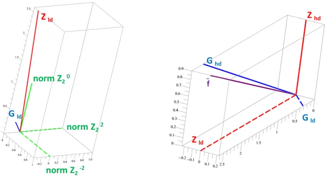
In order to better compare the decomposition between both bases and to quantify more precisely the low degree contribution, a new graphical representation is presented on figure 10. The purpose of this figure is to display a graphical vectorial representations of the Zernike vsLD−HV2 classifications after surgery. The
difference in the length of the low degree vector (Gld) in theLD−HV2classification and the low degree vector
(Zld) in the Zernike classification is striking (left). The sum of the low and high degree of each classification
enables the reconstruction of the total wavefront ˜f: ˜f =Zld+Zhd=Gld+Ghd(right).
This representation strongly suggests that the new basis is more representative of the true optical disturbance that remains after surgery, which is mainly caused by high-order aberration modes, whereas the Zernike basis could lead to a misunderstanding and even a wrong diagnosis of the refractive status of the considered eye.
3.3.
Keratoconus
The results for this new case, an eye presenting a keratoconus are depicted on figures 11 and 12. Keratoconus is characterized by a severe corneal deformation, which causes visual disturbances induced by an increase in high-order aberrations that can not be corrected by spectacles.
Figure 11. Keratoconus. Wavefront decomposition in the Zernike and theLD−HV2 basis.
Note in particular on figure 11 that the prism (first order) coefficients in the Zernike decomposition are only here to compensate for the first order terms contained in the analytical expression of Zernike coma aberration modes (Z3±1 coefficients). In theLD−HV2 basis, the astigmatism coefficientsG±22 were confirmed to be best
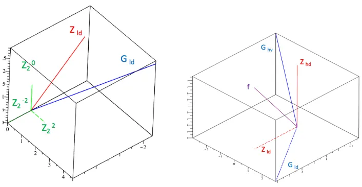
Figure 12. Keratoconus. The low degree contribution in Zernike and LD−HV2 basis.
the differences between both decompositions and the relative contribution of low degree aberrations to the total wavefront. In particular, the low degree contribution to the refractive error in the Zernike decomposition is underestimated because of the presence of low degree terms which have been absorbed in its higher degree component.
4.
Conclusion
A new decomposition basis of the ocular wavefront has been proposed in order to better classify and treat the optical aberrations of the human eye between their lower vs higher degree contribution. As opposed to the Zernike basis, currently used for clinical diagnosis, the new basis introduced here, calledLD−HVL, completely
gathers the low degree terms (lesser thanL) by purifying the remaining higher-order component of the wavefront error, at the only expense of relaxing the orthogonality condition between these two components. On various clinical examples, this new decomposition basis demonstrates its superiority by removing some undesirable artefacts of the Zernike basis, like non existing myopic defocus after myopic surgery, prismatic terms, etc. It also allows to highlight the effect of visually significant aberrations frequently encountered in the wavefront error sensing of various frequent clinical situations, such as spherical aberration, coma, and secondary astigmatism. The lack of orthogonality between the lower and higher order aberrations component may not be detrimental in clinical situations where it is important to address the consequences of the higher-order aberration modes.
References
[1] X. Cheng, A. Bradley, S. Ravikumar, and L. Thibos,Visual impact of zernike and seidel forms of monochromatic aberra-tions., Optom Vis Sci, 87 (2010), pp. 300–12.
[2] J. Liang, B. Grimme, S. Goelz, and J. Bille, Objective measurement of the wave aberration of the human eye using a shack-hartmann wavefront sensor., J Opt Soc Am, 11 (1994), pp. 1949–1957.
[3] B. Platt and R. Shack, History and principles of shack-hartmann wavefront sensing., J. Refractive Surgery, 17 (2001), pp. 573–577.
[4] L. Thibos, R. Applegate, J. Schwiegerling, and R. Webb, Vsia standards taskforce members. vision science and its applications. standards for reporting the optical aberrations of eyes., J. Refractive Surgery, 18 (2002), pp. 652–660.
[5] ,The 2012 charles prentice medal lecture: wavefront measurement of refractive state., Optom Vis Sci, 90 (2013), pp. 911– 23.
[7] F. Zernike,Diffraction theory of the knife-edge test and its improved form, the phase-contrast method, Monthly Not. of R. A.