Development of Power-Assisted Wheelchair with
Consideration of Driving Environment—
Dynamic Estimation of Slope Angle and
Adaptive Control System Design
Takuma Matsui, Shinsaku Fujimoto, Koji Yoshida, and Tetsuya Akagi
Department of Intelligent Mechanical Engineering, Okayama University of Science, 1-1 Ridaicho, Kitaku, Okayama, 700-0005 Japan
Email: [email protected], [email protected], [email protected], [email protected]
Abstract—The purpose of the present paper is to realize a high functionality of a power-assisted wheelchair with consideration of the driving environment. It is very important to recognize the environment in order to support wheelchair users and caregivers. In this paper, sensors are used to measure the state of the environment where is slope angle of uphill. Since these sensors implement to the wheelchair, the driving acceleration of wheelchair might influence the observed slope angle of the environment. This paper deals with the estimation problem of slope angle with acceleration compensation based on low-cost sensors. And this report also describes the adaptive control system design that is combined the estimation method of the slope angle. The effectiveness of the proposed estimation method and the adaptive control design is confirmed by simulation and experimental results. Finally, the proposed power-assisted wheelchair is evaluated by the biological signal such as an electromyography (EMG).
Index Terms—power-assisted wheelchair, dynamic estimation, inclination sensor, adaptive control system, low-cost sensor, EMG, RMS
I. INTRODUCTION
According to “The 2013 White Paper on an Aging Society” [1] published by the cabinet office, the total population of Japan is 127.52 million. The aged population comprised of persons 65 years over is 30.79 million which is the largest number ever. The ratio of the aging population (65 years over) was 24.1% in 2012, but will increase to 39.9% in 2060, showing that Japan has become a super-aged society in 2007. The ageing of the population raises the risks of a decline in the working population (shortage of caregivers) and an increase in pressure on government finances due to pension payments and medical expenses. In a super-aged society, it is very important to take advantage of engineering support for elderly assist. As one of engineering support and mobility support, power-assisted wheelchair which assists driving torque using actuators (electric motors) and spread their areas of life has been enhanced. The
Manuscript received April 15, 2014; revised June 19, 2014.
power-assisted wheelchair combines human torque which is delivered by the arms through the push-rims with output torque of electric motors. However, the power-assisted wheelchair increases the driving torque, responding to the environments (up-hill). Therefore, the excessive driving torque often causes a dangerous behavior of wheelchair. Moreover, the muscular power of the wheelchair user is decreased by the excessive assisting torque.
The purpose of this paper is to realize a high functionality of a power-assisted wheelchair with consideration of the driving environment. Some researchers [2] [3] have proposed the control system design method using the disturbance observer. However, the disturbance observer would be estimated as the disturbance terms including the modeling error, rolling friction and gravity term. The control performance of the disturbance observer becomes to be oscillatory generally. Therefore, the vibration of wheelchair feels the fear to the user.
II. DESCRIPTION OF POWER-ASSISTED WHEELCHAIR
In this chapter, we explain the dynamic model of wheelchair by driving torque of human on the driving environment that is the slope road of uphill or downhill. The dynamic model of the power-assisted wheelchair is extended by adding output torque of electric motor. Two motors that assist the user are equipped in each wheel.
A. Dynamic Model of Wheelchair
Fig. 1 shows the power-assisted wheelchair (Yamaha Motor Co. Ltd., JW-2) used in parameter identification and experiments. Motors that assist the user are equipped in each wheel. For the motion equations for the wheelchair as shown in Fig. 2, a mechanical model [5] has been used which gave the following equation:
) sin cos
(μ θ θ
Mg x K x M
f (1)
where x is the displacement of moving direction, M, K and μ denote total mass of user and wheelchair, the coefficient of viscosity and coefficient of rolling friction, respectively. θ is the slope angle. g denotes the gravity acceleration. The input force f is given to the push rim by wheelchair user.
Figure 1. Power-assisted wheelchair (JW-2)
θ
Mg
sin
θ
Mg
μ
cos
x
K
f
x
R
θ
Mg
θ
Mg
sin
θ
Mg
μ
cos
x
K
f
x
R
θ
Mg
Figure 2. Dynamic model of wheelchair
B. Dynamic Model of Power-Assisted Wheelchair
The power-assisted wheelchair combines human torque τH which is delivered by the arms through the
push-rims with output torque τM of electric motors. The
human torque of each push-rim is measured by the toque sensor which is equipped on wheel device. Therefore, the dynamic model of the power-assisted wheelchair extends the wheelchair model eq. (1), by means of adding output torque of electric motor as following equation:
) sin cos
(μ θ θ MRg
x KR x MR τ τ
τ H M (2)
where R is the radius of rear wheel.
In order to realize a high functionality of the power-assisted wheelchair, it is necessary to estimate the state of the driving environment that is slope angle θ of uphill or downhill. Thus, we describe the dynamic estimation method of slop angle in next chapter.
III. DYNAMIC ESTIMATION METHOD OF SLOPE ANGLE
Many researchers [6] [7] have used the Kalman filter or the nonlinear observer to estimate the attitude of the rigid body with various kind of sensors for the acceleration motion. However, the modeling of noise characteristics and the turning of Kalman filter parameters are difficult. Thus, this paper deals with the estimation problem of slope angle (one of attitude) with acceleration compensation based on inclination sensor. We will describe the dynamic estimation method using two inclination sensors in this chapter.
A. Inclination Sensor Model
)
(
s
G
+)
(
s
G
A +y
Inclination Sensor
θ
u
1
x
u
2
)
(
s
G
+)
(
s
G
A +yy
Inclination Sensor
θ
u
1
x
u
2
Figure 3. Inclination sensor model
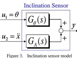
In this paper, the inclination sensor model is applied as a two-input single-output system. Suppose that the inclination sensor model is the linear system. Fig. 3 shows the block diagram of the inclination sensor model. Thus, the dynamic model of inclination sensor gives as the following equation:
2 1 ( )
)
(s u G s u G
y A (3)
where u1=θ and u2=
x
are two input signals of the slopeangle and the translational acceleration, respectively. y is the output signal of the inclination sensor. Gθ(s) denotes
the transfer function between the output and input of slope angle. GA(s) denotes the transfer function between the output and input of translational acceleration. Since these transfer functions are unknown in general, we identify the unknown system based on the system identification [8].
B. System Identification for Inclination Sensor
x
y x
z Inclination Sensor 1(Pitch)
Inclination Sensor 2(Pitch)
Inclination Sensor(Yaw)
y
x
y x
z Inclination Sensor 1(Pitch)
Inclination Sensor 2(Pitch)
Inclination Sensor(Yaw)
y
In this section, we explain the identification method of )
(s
Gθ and GA(s), using the real inclination sensor(Midori
America Co. Ltd., UV-1W) as shown in Fig. 4, The transfer function Gθ(s) is identified by the data of rotary
motion. The transfer function GA(s) is identified by the data of translational motion (Slope Angle: u1=0). The
main conditions of identification experiment are shown as follows:
・Sampling Period : 0.01 [s]
・Sampling Number : 4096
・Input Data: Pseudo Random Binary Signal (Maximum Length)
・Model: ARX-Model (Auto-Regression with eXtra Inputs Model)
・Criterion of Fit: AIC (Akaike’s Information Criterion) The Akaike’s Information Criterion is a way of selecting a model (order and structure) from a set of models.
C. Identification of Gθ(s): Rotary Motion
We need the transfer function Gθ(s) for how output
signal y depends on input signal u1. Thus, in order to
identify the function Gθ(s), we made the experimental
device (See Fig. 5) which is driven by DC motor for the rotary motion (Translational Acceleration: u2=0).
We measure:
・Input u1: Rotary encoder data
・Output y : Inclination sensor data
DC Motor Encoder
Inclination Sensor1
1
u
InclinationSensor2 DC Motor
Encoder
Inclination Sensor1
1
u
InclinationSensor2
Figure 5. Experimental Device for Rotary Motion
As the results of system identification, Gθ(s) was
obtained as the first order transfer function:
2 . 13
2 . 13 )
(
1
s u
y s G
The bandwidth 13 rad/s is the same value as response frequency 2 Hz of the sensor specification. Since order of AIC-model is generally high, the obtained model is the low-dimensional model (Reduced-order modeling by dominant eigenvalue technique) using the AIC-Model.
D. Identification of GA(s): Translational Motion
We need the transfer function GA(s) for how output
signal y depends on input signal u2. Thus, in order to
identify the function GA(s), we made the experimental
device (See Fig. 6) which used the ball screw driving mechanism for the translational motion (Slope Angle: u1=0).
We measure:
・Input u2: Rotary encoder data
・Output y : Inclination sensor data
As the results of system identification, GA(s) was
obtained as the second order transfer function:
26 9 s 34.7 s
1980 )
( 2
2
u y s GA
Encoder
x
u
2
DC MotorInclination Sensor1 Inclination
Sensor2
Ball Screw Encoder
x
u
2
DC MotorInclination Sensor1 Inclination
Sensor2
Ball Screw
Figure 6. Experimental device for translational motion
E. Dynamic Estimation Method
We consider the dynamic estimation method of slope angle and acceleration information, using two inclination sensors of the same type. The dynamic models of two sensors can be rewritten as the following equations:
1 1
( )
1 A1( )
2y
G
s u
G
s u
: Inclination Sensor 1 (4.1)2 2( ) 1 A2( ) 2
y G s u G s u : Inclination Sensor 2 (4.2)
If the acceleration input u2 with high accuracy is
obtained by eq.(6) (Inclination Sensor 2), the estimated value of the slope angle θE = u1 can be easily calculated
by eq.(5):
] ) ( )[
( )
( 1 1 2
1 1
1 G s F s y G s u
u
θE θ θ A
(5)
If the slope-angle input u1 with high accuracy is
obtained by eq.(5) (Inclination Sensor 1), the estimated value of the translational acceleration
x
E
u
2 can be easily calculated by eq.(6):] ) ( )[
( )
( 2 2 1
1 2
2 G s F s y G s u
u
xE A A θ
(6)
where Fθ(s) and FA(s) are appropriate low-pass filters.
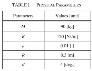
TABLE I. PHYSICAL PARAMETERS
Parameters Values [unit]
M 90 [kg]
K 120 [Ns/m]
μ 0.01 [-]
R 0.3 [m]
θ 4 [deg.]
estimation method. From Fig. 6, the effectiveness and of the proposed estimation method (Eqs. (5) and (6)) was confirmed by the simulation in the Matlab/Simulink. For the numerical simulation, we used the values shown in Table I. These parameters represent the physical parameters of the wheelchair and the driving environment.
Figure 7. Proposed estimation method
(a) Estimationed inclination angle
(b) Estimationed acceleration
Figure 8. Simulation results of dynamic estimation method
IV. CONTROL SYSTEM DESIGN
Control system design will be discussed in this chapter for task such as the adaptive-control system design consisting of the control law and the estimation law.
A. Adaptive Control System Design
In order to extend the foregoing estimation to the unknown parameter case, we use the linear in the parameters property of wheelchair dynamics. Now, consider eq. (1) in closed loop with:
where ^ denotes the estimation value, θE is the estimated
slope-angle,
x
d is the desired trajectory andT
] ˆ ˆ ˆ [
ˆ M K μM
φ represents a vector of unknown
parameters (∵μM μM).
And a vector of unknown parameter
φ
ˆ
adjusted byS
T
ˆ ΓY
φ
S
e
λ
e
(8)where λ is a positive parameter.
By the Lyapunov’s theorem, the control error e and
e
converge to 0 as time tends to infinity. Thus, we have proved the validity of the adaptive control design consisting of the control law (eq. (7)) and estimation law (eq. (8)).
B. Simulation Results
The simulation of the adaptive control was performed on the Matlab/Simulink. Values of physical parameters are same values of the simulation as Table I of Chapter 3. The feedback gains of the servo compensation ware chosen to be KP=100Nms, KD=20Nm. Fig. 9, shows the
results of the control performance and the physical parameters. From Fig. 9, the effectiveness of the proposed adaptive control design was confirmed by the simulation.
(a) Control performance
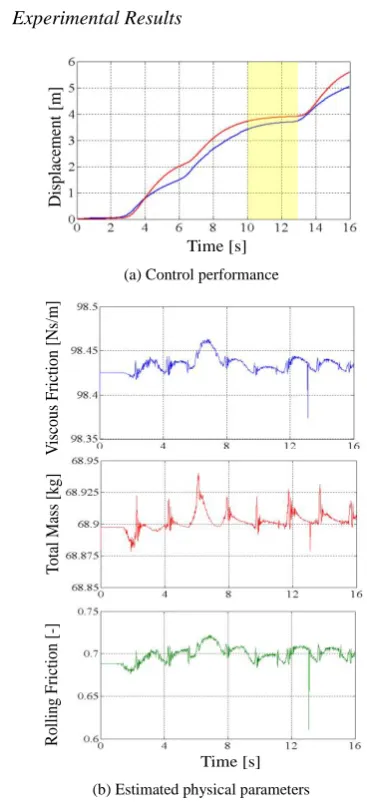
C. Experimental Results
D
isplac
emen
t
[m]
Time [s] (a) Control performance
V
isc
ous
Fric
tion
[N
s/m]
T
otal
Mass [
kg]
R
oll
ing F
ric
ti
on
[-]
Time [s] (b) Estimated physical parameters Figure 10.Experimental results of the adaptive control
Fig. 10(a), shows the experimental results of the control performance During the 13 s from about 10 s, the wheelchair user released the hand from the push-rim on the slope(Slope Angle: θ = 4.0 deg.). From Fig. 10(a), the user was able to ride the wheelchair with hands-free. And the wheelchair was stopped on the slope. Fig. 10(b) shows the estimation results of the physical parameters. Since the estimation law (eq. (8)) might influence the observed sensor noise, all estimated values are vibrating, but these values converge to substantially constant values. From the above results, the effectiveness of the adaptive control design was confirmed by the experimental results.
V. EVALUATION OF POWER-ASSISTED WHEELCHAIR
In this paper, an ideal power-assist system for the wheelchair is that the user can operate the wheelchair in the force-feeling like the level ground without influence of the driving environment. It is not that the user can operate the wheelchair by means of a small force. Therefore, the proposed power-assisted wheelchair is evaluated by the biological signal such as an electromyography (EMG).
A. Measurement System and Position
Upper-arm muscle activities are documented with three polar amplified surface electrodes (Wireless EMG Sensor (LP-WS1221) as shown in Fig. 11, Size:26.6×18.4×7.4mm, Mass:20g , Logical Product Co.) with a single ground electrode, and are placed (See Fig. 12) on an adductor pollicis muscle, the triceps brachii muscle and biceps brachii muscle. The data of an adductor pollicis muscle, is used to determine exactly period which holds the hand rim of the wheelchair. These muscles are chosen for their role in elbow flexion and extension.
Figure 11.Wireless EMG sensor (LP-WS1221)
Biceps Brachii (Elbow Flexion)
Triceps Brachii (Elbow Extension)
Adductor Pollicis (Thumb Adduction)
Biceps Brachii (Elbow Flexion)
Triceps Brachii (Elbow Extension)
Adductor Pollicis (Thumb Adduction)
Figure 12.Measurement placement (Right Arm)
The skin surface is prepared by cleaning the area with an alcohol preparatory. After three EMG sensors are secured, EMG data are saved into the hard disk, which is connected to the computer via wireless sensors. The data are collected at the law voltage values with gain settings (amplified 500 times the input signal). The data are sampled on a computer at a rate of 100Hz.
B. Data Processing and Analysis
This study focused on data derived from the right upper limb during the propulsion (contact) phase of the push stroke only. Healthy participant was asked to propel their wheelchair at constant pace (about 0.5Hz) for 10s. EMG from five successive push strokes were collected; once data collection began, the initial one push strokes were neglected, and the next four consecutive push strokes were saved for analysis. Fig. 13 shows the integral EMG signals of two placements (an adductor pollicis muscle and the triceps brachii muscle).
Figure 13.Measurement results of iEMG signal
RMS (Root Means Square) value is extracted by calculating the integral EMG from the raw EMG signals. The σRMS is determined as:
N
i i RMS x
N σ
1 2
1
where xi is the intgral EMG signal of the triceps brachii
muscle at i th sampling and N is the number of samples in a segment.
0.00 0.02 0.04 0.06 0.08 0.10 0.12
Without Assist With Assist Without Assist With Assist
Commercial Product(JWX-2) Proposed Wheelchair
Down Constant
σ
RMS
[V
]
:Level Ground :Up-hill(θ=4.0 deg.)
0.00 0.02 0.04 0.06 0.08 0.10 0.12
Without Assist With Assist Without Assist With Assist
Commercial Product(JWX-2) Proposed Wheelchair
Down Constant
σ
RMS
[V
]
:Level Ground :Up-hill(θ=4.0 deg.)
Figure 14.Comparison between commercial product and propoed wheelchair (RMS Values)
Fig. 14 shows results of the performance comparison between the commercial product (Yamaha Motor Co. Ltd., JWX-2: Latest Type) and the proposed wheelchair. Commercial product is caused excessive assist. In case of the proposed wheelchair, the participant can operate the wheelchair in the force-feeling like the level ground without influence of the driving environment (Up-hill).
VI. CONCLUSION
The purpose of the present paper is to realize a high functionality of a power-assisted wheelchair with consideration of the driving environment. In order to measure the state of the driving environment where is slope angle of uphill or downhill, we proposed the dynamic estimation method using the two inclination sensors of the same type. And this paper also proposed the adaptive control system design that was combined the estimation method of the slope angle. The proposed method could estimate physical parameters that are total mass of user and wheelchair, coefficient of rolling friction and viscous coefficient. The effectiveness and the validity of the proposed estimation method and the adaptive control design ware confirmed by simulation and experimental results. Finally, the effectiveness of the
proposed wheelchair was confirmed by the biological signal such as an electromyography (EMG).
ACKNOWLEDGMENTS
This work was supported by Grant-in-Aid for Scientific Research (C) 25350696.
REFERENCES
[1] The 2013 White Paper on an Aging Society. Cabinet Office,
Government of Japan. [Online]. Available:
http://www8.cao.go.jp/kourei/whitepaper/w-2013/zenbun/25pdf_index.html (in Japanese)
[2] H. Seki, M. Iso, and Y. Hori, “How to design force sensorless power assist robot considering environmental characteristics-position control based or force control based,” in Proc. the 28th Annual Conference of the IEEE Industrial Electronics Society, Sevilla, 2002, pp. 2255-2260.
[3] K. Kim, K. Nam, S. Oh, H. Fujimoto, and Y. Hori, “Two-dimensional assist control for power-assisted wheelchair considering straight and rotational motion decomposition,” in
Proc. the 38th Annual Conference on IEEE Industrial Electronics Society, Montreal, 2012, pp. 4278-4283.
[4] H. Berghuis, R. Ortega, and H. Nijmeijer, “A robust adaptive robot controller,” IEEE Transactions on Robotics and Automation, vol. 9, no. 6, pp. 825-830, 1993.
[5] R. A. Cooper, “A system approach to the modeling of racing wheelchair propulsion,” Journal of Research and Development, vol. 27, no. 2, pp. 151-162, 1990.
[6] R. Zhu, D. Sun, Z. Zhou, and D. Wang, “A linear fusion algorithm for attitude determination using low cost MEMS-based sensors,” Measurement, vol. 40, pp. 322–328, 2007.
[7] A. E. Hadri and A. Benallegue, “Attitude estimation with gyros-bias compensation using low-cost sensors,” in Proc. Joint 48th IEEE Conference on Decision and Control and 28th Chinese Control Conference, Shanghai, 2009, pp. 8077-8082.
[8] L. Ljung, “System identification-theory for the user-second edition,” Prentice Hall, pp. 8-12 and 79-139, 1999.
Takuma Matsui is a graduate student at Okayama University of Science. He received the Bachelor of Engineering from Okayama University of Science in 2013.
Shinsaku Fujimoto is currently an associate Professor of Intelligent Mechanical Engineering Department in Okayama University of Science, Japan. He received the Master of Engineering and the Doctor of Engineering from Okayama University of Science in 1992 and 1995, respectively. From 1995, he was a faculty of Okayama University of Scienec, Japan. His research interests include control and robotics, especially biped robot using McKibben artificial muscle and power assisted wheelchair.
Tetsuya Akagi is currently a Professor of Intelligent Mechanical Engineering Department in Okayama University of Science, Japan. He has been working in this university since 2005. He received the Master of Engineering and the Doctor of Engineering from Okayama University of Science in 1995 and 1998, respectively. From 1998 to 2005, he was a faculty of Tsuyama National College of Technology, Japan. His research interests include mechatronics and robotics; especially wearable control systems using microcomputers and wearable control devices such as flexible pneumatic actuator, soft sensor and wearable control valve.