Iranian Journal of Electrical & Electronic Engineering, Vol. 14, No. 3, September 2018 213 S. Mohammad Nejad*(C.A.), H. Arab* and N. Ronagh Sheshkelani*
Abstract: In this paper, after a brief overview on laser warning system (LWS), a new structure for an optical array that is used in its optical subsystem is introduced. According to the laser threats’ wavelengths (0.5 – 1.6 µm) and our desirable field of view (FOV), we used 6 lenses for gathering the incident radiation and then optimized the optical array. Lenses’ radius, their semi diameter, their distance from each other, their thickness and the kind of glass used in them was chosen in which we access a very high transmission coefficient. Also the optical reflection and absorption of the array decreases at the same time. After optimization, the obtained optical transmission in our desirable FOV is up to 82% and the obtained optical reflection and absorption is less than 15%. Total aberration of the incident ray decreased notably and the results showed that this parameter is less than 2µm. The laser spot diameter which is focused on the detector is smaller than 400 µm in the worst case which is the laser radiation with 1.54 µm wavelength and field of 10 degrees. Total track of the array is 66.819 mm and effective focal length and F/# parameter are as small as possible which leads to high quality of the light’s focus on the detector and smaller dimension and lighter weight for the receiver. Using optical devices with such appropriate arrangement and very good optical transmission coefficient, the offered structure has a remarkable signal to noise ratio (SNR) which is up to 160 dB. The receiver’s operation in far distances from laser sources (beyond 15 km) and in hazy conditions and low temperatures is quite suitable as well.
Keywords: Laser Warning Systems, Threat Detection, Optical Array, Field of View, Aberration, Optical Transmission.
1 Introduction1
n the last century, with development of science and technology, guided weapons with high accuracy has been prevailing. The laser-guided equipment threatens the strategic platforms. These advanced equipment combines electronic devices with the best optical technologies. Hence, the development of a high-precision laser warning system is an essential requirement to protect the important centers such as planes, ships, armored vehicles, tanks, factories etc. In
Iranian Journal of Electrical & Electronic Engineering, 2018. Paper first received 01 November 2017 and accepted 28 February 2018.
* The authors are with the School of Electrical Engineering Iran University of Science and Technology (IUST), Tehran, Iran.
E-mails: [email protected], [email protected] and
Corresponding Author: S. Mohammad Nejad.
fact, the purpose of these systems is detecting the optical signals from a wide range of incident angles and determining the characteristics of the threatening sources. This extracted information is used in active defense systems [1-4].
In this paper, we introduce the defensive systems and its components in elementary sections. In the next sections, the requirements of the system, threat detection methods and effective parameters in designing are investigated. Finally, an optimized optical array is designed and its characteristics are studied.
2 Laser Warning System and Its Requirements
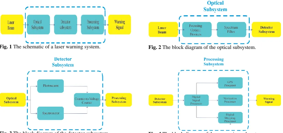
A laser warning system consists of an optical subsystem, a detection subsystem, and a processing subsystem. The incident laser beam is focused and directed by the optical subsystem and transmitted toward the detection subsystem. In response to the
I
Iranian Journal of Electrical & Electronic Engineering, Vol. 14, No. 3, September 2018 214
optical signal, a digital signal is generated by detection subsystem. Finally, the processor subsystem produces the warning output which contains the characteristics of the laser radiation. This information can be used to have an appropriate countermeasure against laser-guided weapons. The components of the laser warning system are shown in Fig. 1 [4-11].
The optical subsystem may contain reflectors, fiber bundles, beam splitters and lenses to focus and navigate the incident laser beam. In addition, other components such as filters are used to reduce the effects of background noises. A block diagram of this subsystem is shown in Fig. 2 [4-11].
The detector subsystem receives the focused light and provides a digital signal in response to the optical signal. As it shown in Fig. 3, this subsystem may include different kinds of photo-sensors, a spectrometer, and a current-to-voltage converter. In addition, a day-light sensor can be applied to detect sunday-light. In response to the incident laser beam, the photo-sensor generates free electrons to convert the focused light into current and the spectrometer determines the wavelength of the incident beam. The photo-sensor is the main part of the detection subsystem and we can use CCD, CMOS or CMT sensors for this part [4-17].
The processing of the digital signal which is generated by detection subsystem is very critical. This subsystem
consists of digital signal processors to determine the azimuth and elevation angle of the laser beam source. Other components such as GPS, a navigation processor, and a digital ground mapping processor are used to determine the location of the laser beam source. The block diagram of this subsystem is shown in Fig. 4 [2,4,13,18].
These warning systems should be able to distinguish different kinds of threats. In fact, the characteristics of the incident beam are measured and compared with the pre-stored data in the processor to determine the type of the threat. Laser rangefinders (LRF), laser target designators (LTD), and laser beam riders (LBR) are the conventional laser threats. The characteristics of these three types of laser threats are summarized in Table 1. Also, the incident angle and direction of the laser beam is used to determine the position of the laser beam source [2,19-25].
In addition, this system should be able to face multiple threats and separate them from each other, simultaneously. Also, the scattered and reflected beams by surfaces and atmosphere should be distinguished to reduce the false alarm rate. Finally, the last requirement for this warning system is to communicate with the central processor and other countermeasure systems [2].
Fig. 1 The schematic of a laser warning system.
Fig. 3 The block diagram of the detector subsystem.
Fig. 2 The block diagram of the optical subsystem.
Fig. 4 The block diagram of the processing subsystem.
Table 1 Typical laser threat sources characteristics [38].
Characteristics LRF LTD LBR
Typical laser peak (W) 106 106 A few
Laser beam divergence (mrad) A fraction of A fraction of Several (variable)
Power density at the target High (on axis)
Low (off axis)
High (on axis) Low (off axis
Very low (on axis) Undetectable (off axis)
Wavelength (µm) 1.06 and 1.54 1.06 Near IR
Speed of the associated weapon (Mach) 2 1-2 Up to 4+
Iranian Journal of Electrical & Electronic Engineering, Vol. 14, No. 3, September 2018 215
3 Threat Detection Methods and Effective
Parameters in Designing
There are several methods to determine the characteristics of the incident laser beam such as Fabry-Perot etalon, Michelson interferometer, Fizeau interferometer, and grating diffraction. Fabry-Perot etalon is based on the interference between multiple reflections of a light beam and two surfaces of a thin plate. In addition, this optical resonator is able to split the incident light into many coherent beams and it is used to measure the wavelength of incident ray [2,26]. The Michelson interferometer has good resolution, whereas its sensitivity is very low. Also, it needs an imager such as CMOS image sensor or area array CCD to receive signals. On the other hand, its hardware circuit is complex and processing of the signal is hard. Fizeau interferometer is used to detect the frequency of the incident light and also able to separate the wavelengths of oriented parallel surfaces. So, it is suitable for rapid detection of pulsed laser sources. Compared to others, this interferometer is able to measure variety kinds of wavelengths as a function of distance. In addition, it is easily influenced by environment temperature. The last and the best method is grating diffraction. The advantage of this route is to determine the wavelength and incident angle, simultaneously. In fact, it is the fast and easiest way to calculate these parameters. The systems using this method are able to measure the bandwidth of the wideband pulse lasers. Also, it should be mentioned that this method has high sensitivity and good resolution [9,13,19,26,27].
The effective parameters in designing the laser warning system are related to the source of the laser beam, atmosphere and the receiver. The first group of parameters is related to the source of the threat which is usually approximated by a Gaussian distribution beam [28,29].
The second group is related to parameters which are affected by the atmosphere. These effects will be studied in two parts; the first part includes parameters that change the intensity of the laser beam. To investigate these cases, the effects of absorption and scattering of laser radiation should be considered. The second part consists of parameters that change the laser beam spatial characteristic. The components of this group such as; temperature changing, moisture, and density of particles in the atmosphere change the refractive index of the atmosphere. So, the Kolmogorov equation should be used to investigate these disturbances. Due to the absorption and scattering, the laser beam is attenuated in the atmosphere. This attenuation and the amount of the beam alteration are depended on the wavelength and output power of laser radiation and the characteristic of the atmosphere. When the ray is low power, the behavior of the effects tends to be linear. Absorption, scattering, and the atmospheric
turbulence are the examples of the linear effects. On the other hand, new non-linear effects will observe if the power of the ray is high enough. Some significant non-linear effects which can be placed in this category are thermal blooming, kinetic cooling, beam trapping, two-photon absorption, bleaching and atmospheric breakdown [28,30-36].
The third category includes parameters such as aperture diameter and focal length of the optical array which is related to laser beam receiver. An optimized system with high sensitivity and low noise will be achieved by adjusting the parameters of this group [29].
4 Proposed Optical Subsystem
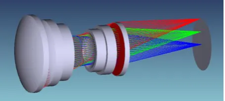
As mentioned, the optical subsystem is used to gather the incident beam, determine the field of view (FOV) and direction of the laser beam source. This subsystem may include reflectors, fiber bundles, beam splitters and lenses to focus the incident beam on the photodetector. In this proposed subsystem, our purpose is designing the lenses which can gather and transmit the light to the detector. The thickness, semidiameter and the radius of the lenses, their distance from each other, and the kind of glasses are optimized to reach the highest optical transmission and reduce the aberration, absorption, and reflection. Furthermore, it should be able to distinguish pulsed laser sources with very narrow width and continuous signals with the wavelength between 0.5 – 1.55 µm. So, the detection of this wide range of signals is very difficult. Also, designing an optical array to gather this wide range of wavelengths is effortful. The structure of proposed optical subsystem is shown in Fig. 5.
In order to gather the light on the detector, 6 lenses are used. It is able to distinguish radiations with 10 degrees over the horizon. So, the field of view of the proposed optical subsystem is 20 degrees.
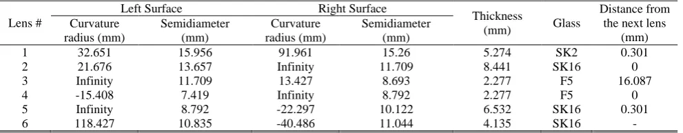
In order to optimize the structure, a global search with a well-known algorithm has been used for three wavelengths of 0.63 µm, 1.06 µm, 1.54 µm and three categories of beams with the angles of 0, 5 and 10 degrees over the horizon. Table 2 shows the obtained values for the lens parameters which are used in proposed structure after optimization.
Matrix of spot diagram for proposed optical array increases with the increase of wavelength and this is
Fig. 5 The 3D schematic of the proposed optical array.
Iranian Journal of Electrical & Electronic Engineering, Vol. 14, No. 3, September 2018 216 Table 2 Parameters of the lenses in the proposed subsystem.
Lens #
Left Surface Right Surface
Thickness
(mm) Glass
Distance from the next lens
(mm) Curvature
radius (mm)
Semidiameter (mm)
Curvature radius (mm)
Semidiameter (mm)
1 32.651 15.956 91.961 15.26 5.274 SK2 0.301
2 21.676 13.657 Infinity 11.709 8.441 SK16 0
3 Infinity 11.709 13.427 8.693 2.277 F5 16.087
4 -15.408 7.419 Infinity 8.792 2.277 F5 0
5 Infinity 8.792 -22.297 10.122 6.532 SK16 0.301
6 118.427 10.835 -40.486 11.044 4.135 SK16 -
shown in Fig. 6. As it can be noticed, the spot diameter because of the characteristics behavior of Gaussian beams propagation that will be calculated as (1) [39]:
2
0 2
0
( ) 1 z
W z W
W
(1)
In (1), W(z) is the spot diameter in an arbitrary z, W0 is
the minimum spot diameter and λ is the wavelength of the radiation. Gaussian beam is an ideal beam and according to (1),W(z) increases with increase of λ. It could be argued that more divergence of radiation in the laser source causes the increase of spot diameter with increase of the field.
We can see that the optical array has focused the radiation on the detector as well, and in the worst case with the wavelength of 1.54 µm and field of 10 degrees, the spot diameter is about 400 µm and due to the detector size, the detector would not have any problem in detecting the laser radiation.
Another important parameter which should be considered in designing of the optical array is the aberration. Fig. 7 shows the ray aberration for the proposed optical array. Horizontal and vertical axis in this picture represent the entrance pupil of optical array and the errors which occur in the direction of axis “Y” and “X”, respectively. An off-axis aberration function at an arbitrary point Q may be expressed as (2) [39]:
4 3 2 2 2
40 31 22
2 2 3
20 11
( ) ' cos ' cos
' ' cos
a Q C r C h r C h r
C h r C h r
(2)
As we can see, off–axis aberration is a function of 3 parameters, r is the distance from the optical axis, θ is the angle with perpendicular line and h' is the height of paraxial image. The C coefficients in (2) are subscripted by numbers that specify the powers of the term dependence on h', r and cosθ respectively. These coefficients are obtained from geometrical optics and they are functions of refractive indexes of the lenses. The dependence of the coefficients on the wavelength is due to the dependence of the refractive indexes to the wavelength but we do not have an explicit formula for this dependence and it’s depending on the glass type. Fig. 7 is a manifestation of chromatic dispersion of the optical array and the reason is the dependence of the
refractive index of the lenses on the wavelength. As a result, radiations with various wavelengths focus on various points in the image plane.
According to Fig. 7, maximum error occurs when the radiation enters from the end of the pupil and also when the wavelength increases which leads to an increase of aberration’ itself. In other hand, symmetry of the curves about the origin shows that the coma aberration in this optical array is demolished. Also, the maximum error in this array, is smaller than the detector size and thus the incident radiation would be detected by the detector as well.
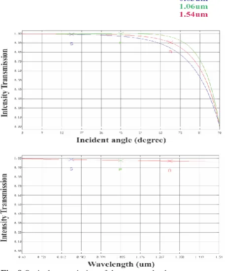
Fig. 8 shows the optical transmission of the proposed optical array. As we can see, after optimizing and selecting appropriate glasses for our lenses, according to 20 degrees of field of view, the transmission of our
Fig. 6 A matrix of the laser spot diagram in the proposed optical subsystem.
Fig. 7 The ray aberration of the optical array.
Iranian Journal of Electrical & Electronic Engineering, Vol. 14, No. 3, September 2018 217
optical array is more than 80% that this value is much more efficient in comparison with common systems with 40% to 60% of transmission [40].
In our design, we used anti-reflection coating on the lenses which not only helps the optimization but also minimizes the reflection of the radiations (less than 10% in all the wavelength range and our field of view) and this parameter is shown in Fig. 9. All transmission and reflection optical spectrums are wavelength depended and this is due to dependence of lenses’ refractive index to the wavelength. In all optical systems the most optical transmission occurs in the field of 0o. this is the
intrinsic property of optical systems and with the increase of angle, optical transmission increases while optical reflection decreases at the same time.
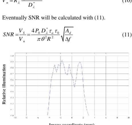
Fig. 10 reveals the relative illumination of our optical array. The light beam usually have a Gaussian distribution and its maximum energy is in the center and as the distance from the center increases, its energy decreases exponentially.
2
0 0 ( )
x x
I x I e
(3)
Equation (3) shows the intensity of a Gaussian beam. The maximum intensity of a beam is I0 and occurs at x = 0. At x = x0, the intensity of the beam becomes
1/eI0. The area below the curve between [-x0, x0] is
much more than outside of this range and 68% of the laser radiation energy will be in this region and Fig. 11 shows this. As we can see in Fig. 10, this event occurs in red region of the figure. By considering of the
Fig. 8 Optical transmission of the proposed subsystem.
detector’s size which is bigger than the red region of this figure, we do not have any problem for detecting the radiation. An ideal optical subsystem should be able to pass signals as much as possible and focus them on the light detector. So, the process of the radiation detection will be done without any problem.
According to Fig. 12, the laser beam will be focused on the detector with the dimensions up to about 1mm. This figure is another manifestation from Fig. 6 which is obtained from simulation and shows the spot diagram in one dimension and confirms the system performance. Fig. 13 shows the Seidel diagram of the optical array. The Seidel Diagram shows the Seidel aberration coefficients as a histogram for each surface, and as a system sum. It helps to identify easily those surfaces that add or subtract most of a certain aberrations, and also which surfaces are balancing aberrations. This diagram is presented to better identify the system’s aberrations and to find a better view of the system
.
This figure demonstrates all of the laser beam aberration including spherical, coma, astigmatism, field curvature, distortion, axial color and lateral color that occurs along the optical array in each surface of it. As we can see, total distortion and aberration which occur on the laser signal is very small (less than 2 µm) that reveals the optimal and appropriate design of the optical array. It should be mentioned that the effective focal length ofFig. 9 The reflection of the proposed subsystem.
Iranian Journal of Electrical & Electronic Engineering, Vol. 14, No. 3, September 2018 218
this array is exactly equal to 50 mm and total track of this optical array is 66.819 mm. So we can see that these parameters are as small as possible and thus the dimension of the system gets smaller and its weight gets lighter compared to common systems. Also F# parameter is 2.889 and this value provides better quality of gathering the rays in comparison with common systems that their F# is more than 3.
One of the most important parameters that should be checked in the mentioned array is the signal to noise ratio (SNR). The process of calculating will be explained in the following [41]:
dR (4)
where d is laser spot’s diameter on the detector, θ is laser’s divergence in radian and R is distance from the laser source to the detector. So the laser spot’s area on the detector can be obtained from (5).
2 2 2 2
2 4 4
d d R
A
(5)
For calculating the irradiance, (6) is used.
0 a
P E
A
(6)
In (6), P0 is the peak power of the laser source and τa is
the atmospheric attenuation for the laser in a special wavelength. So the power on the detector is calculated with (7).
Fig. 10 The relative radiation of proposed optical subsystem.
I0
- x0 0 x0
1/e I0
68% of energy
Fig. 11 Intensity of a Gaussian beam.
0 0 0
0 0 2 2
4
a d a
d d d
P P A
P E A A
A R
(7)
where Ad is the detector’s area and τ0 is the optical
transmission coefficient. When the laser radiation hits the detector’s surface, the maximum voltage of the detector can be obtained from (8).
0 0
2 2
4 d a
S d
P A
V R P R
R
(8)
In (8), Rλ is the spectral responsivity of the detector in a
special wavelength and is obtained from equation (9).
* n
d
V
R D
A f
(9)
In equation (9), Dλ*is detective parameter in a particular
wavelength, Δf is the detector’s bandwidth and Vn is
environmental noise signal voltage. So we have:
*
d n
A f
V R
D
(10)
Eventually SNR will be calculated with (11).
*
0 0
2 2
4
S a d
n
V P D A
SNR
V R f
(11)
Fig. 12 The radiation pattern of the laser beam in terms of the coordinates and the dimension of the detector.
Fig. 13 Seidel diagram of the optical array.
The atmospheric attenuation τa for the lasers in near IR
Iranian Journal of Electrical & Electronic Engineering, Vol. 14, No. 3, September 2018 219
wavelengths can be obtained with a function of distance (R) and also extinction coefficient (σ) by (12).
R
a e
(12)
In [37], there are extinction coefficients for different lasers in 5 atmospheric and 2 aerosol conditions based on the distance. 2 aerosol conditions include a condition without any aerosol particles and clear which visibility in this way is up to 23km, and another condition is the hazy one which visibility limits to 5 km.
If the worst atmospheric condition which means semi– polar condition in winter, is selected, the extinction coefficient is 0.08724/km for clear and 0.42734/km for hazy conditions.
If InGaAs APD is used as the detector, lasers with wavelengths shorter than λmax = 1.55µm can be detected
and with this in mind that lasers used in battlefields work in the wavelength range between 0.5 µm – 1.6 µm, using this detector for each array can be a good choice. Of course if more detectors with different wavelength range is used in a way that divides the intended spectrum into more parts and an appropriate filter is used for each part, we can obtain better accuracy. For InGaAs APD, the Dλ* is about
1015 (cm.Hz0.5.W-1). Most of the laser threats use pulses
with 5 – 500 nsec widths, so considering 5nsec pulse width, the detector’s bandwidth limits to Δf = 200 MHz. If we consider the laser’s peak power equal to 107 W
and the laser’s ray divergence equal to 0.5 mrad, knowing the transmittance coefficient of optical devices and the detector’s active area which is 0.05 cm2, the
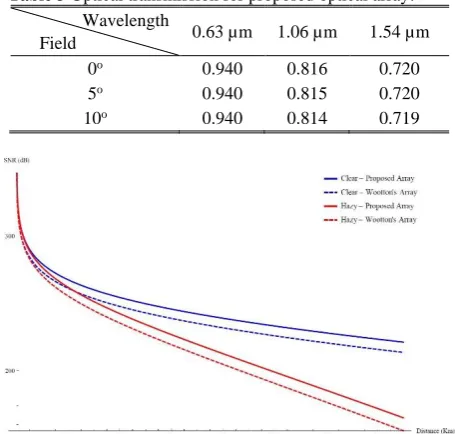
SNR in clear and hazy conditions as a function of distance diagram can be drawn for our optical array. Table 3 shows the obtained optical transmission for our optical array after optimization.
According to Table 3 and other parameters that represented, the SNR diagram vs. distance is shown in Fig. 14.
Based on Fig. 14, it is plain to see that SNR for both clear and hazy conditions in near distances is a great and remarkable value and shows an improvement of several orders in comparison with presented structure by J. R. Wootton in [41]. On the other hand, the majority of distance that still can use this array is more than 15km which in modern operating systems is a noteworthy value.
5 Conclusion
Laser warning systems have a vital role in the defensive systems of each country. These systems are composed of several sub-systems which are designed according to the consideration of each project. These receivers should be able to detect threats and their parameters to have an appropriate countermeasure. In this paper, a new structure was proposed for optical array. In order to gather the light on the detector, 6 lenses were used to distinguish radiations with narrow
Table 3 Optical transmission for proposed optical array. Wavelength
Field 0.63 µm 1.06 µm 1.54 µm
0o 0.940 0.816 0.720
5o 0.940 0.815 0.720
10o 0.940 0.814 0.719
Fig. 14 Signal-to-Noise Ratio for the proposed optical array in clear and hazy atmospheric conditions.
bandwidth and 10 degrees over the horizon. So, the field of view of the proposed optical subsystem is 20 degrees. After optimization of the array, the optical transmission of our array was obtained more than 80%. This value is more than usual values in conventional systems and leads to considerably higher SNR. Also, using the anti-reflection coating reduces the reflection rate less than 10% and other important parameters in our optical array are quite suitable as well. Consequently, the proposed optical array is able to focus the laser beam on the detector, accurately.
References
[1] C. Jinxi, Z. Jinchun, W. Hongjun and C. Bin, “Error Analysis of Angular Resolution for Direct Intercepting Measurement Laser Warning Equipment,” in Selected Papers of the Chinese Society for Optical Engineering Conferences held July 2016, Vol. 10141, p. 101410U, 2016.
[2] M. Jurba, E. Popescu, S. Cojocaru, D. Guiman and D. Stroe, “Extended spectral range laser receiver,”
Optoelectronics and Advanced Materials-Rapid Communication, Vol. 6, No. 11, pp. 1181–1184, Nov. 2012.
[3] D. Goular, J. P. Cariou, D. Fleury, C. Planchat, R. Gouyon, C. Besson, A. Bêche and V. Megaides, “Off-axis Laser Warning Sensor,” in Laser Radar
Technology and Applications XIV, Vol. 7323,
p. 732314, May 2009.
[4] D. R. Jungwirth, Laser detection and warning system. U.S. Patent No. 9,134,174. Sep. 2015.
Iranian Journal of Electrical & Electronic Engineering, Vol. 14, No. 3, September 2018 220
[5] S. Kumar, S. Prakash, A. K. Maini, V. B. Patil and R. B. Sharma, “Design of a Laser-Warning System Using an Array of Discrete Photodiodes: Part II,” Journal of Battlefield Technology, Vol. 14, No. 2, 2013.
[6] B. E. A. Saleh, M. C. Teich and B. E. Saleh,
Fundamentals of photonics. Vol. 22, New York: Wiley, 1991.
[7] M. Bass, E. W. V. Stryland and D. R. Williams,
Handbook of Optics. Vol. 2, McGraw-Hill, 1995.
[8] J. W. Goodman, Introduction to Fourier Optics. 2nd edition, McGraw-Hill, 2004.
[9] J. V. Knuuttila, P. T. Tikka and M. M. Salomaa, “Scanning Michelson Interferometer for Imaging Surface Acoustic Wave Fields,” Optics letters, Vol. 25, No. 9, pp. 613–615, 2000.
[10]MIT Open Course Ware, “The convolution theorem
multiplication convolution,” MIT 2.71/2.710.
04/08/09 wk9-b-18, Page 2, Spring 2009.
[11]J. R. Wootton and G. Waldman, Systems, Methods and Devices for Detecting Light and Determining its Source. U.S. Patent 6,770,865, Aug. 2004.
[12]A. Mallik, D. S. Centre and M. House, “Lasers in Defense,” in Photonic Systems and Applications in Defense and Manufacturing, Vol. 3898, pp. 104– 115, Nov. 1999.
[13]L. Xiao, Z. Jilong, T. Erming, Z. Yue and W. Zhibin “A New Design for Laser Warning System,” in Proceedings of the 7th WSEAS International Conference on Signal, Speech and
Image Processing, Beijing, China, pp. 187–
189\r374, Sep. 2007.
[14]S. O. Kasap and R. K. Sinha, Optoelectronics and photonics: principles and practices. Vol. 340, New Jersey: Prentice Hall New Jersey, 2001.
[15]J. Ying, Y. He and Z. Zhou, “Analysis on laser spot locating precision affected by CMOS sensor fill factor in laser warning system,” in 9th International
Conference on Electronic Measurement &
Instruments (ICEMI), pp. 202–206, Aug. 2009.
[16]Z. Zhou and J. Ying, “Study on Image Processing Technology in Imaging Laser Detection System,” in
Symposium on IEEE Photonics and Optoelectronic
(SOPO),Chengdu, pp. 1–4, 2010.
[17]K. Cabanas-Holmen, D. Dorn and C. Tesdahl, “Characterization and System Modeling of a 5-Mpixel CMOS Array,” in Sensors, Cameras, and Systems for Scientific/Industrial Applications VIII, Vol. 6501, pp. 65010Q–65010Q–10, Feb. 2007.
[18]J. Dubois, Very high angular resolution laser beam rider detector having a gated image intensifier and a video camera. U.S. Patent 5,280,167, Jan. 1994.
[19]L. Fu and Z. G. Hong, “Design of Laser Warning Receiver Based on DSP,” in Asia Pacific
Conference on Postgraduate Research in
Microelectronics & Electronics, pp. 325–328, 2009.
[20]G. Bolander and K. Nissborg, Laser warning device providing a direction of laser radiation. U.S. Patent No. 5,440,116, Aug. 1995.
[21]J. B. Allen and C. R. Coale Jr, Laser beam transmitter system for laser beam rider guidance systems.U.S. Patent 4,111,383, Sep. 1978.
[22]C. E. Nourrcier Jr, Low cost laser range finder
system architecture. U.S. Patent 5,638,163,
Jun. 1997.
[23]L. Xiao, Z. Jilong, T. Erming, Z. Yue and W. Zhibin, “A new design for laser warning system,” in Proceedings of the 7th WSEAS
International Conference on Signal, Speech and Image Processing, Beijing, China, 2007.
[24]J. P. Daniel, Laser Target Designator System. U.S. Patent 4,349,838, Sep. 1982.
[25]W. Miller, T. Peacher, J. Duke and R. Sitton,
Beamrider missile guidance method. U.S. Patent 3,782,667, Jan. 1974.
[26]A. D. McAulay, “Detecting Modulated Lasers in the Battlefield and Determining Their Direction,” in Signal Processing, Sensor Fusion, and Target Recognition XVIII, Vol. 7336, p. 73361J, May 2009.
[27]Z. Jilong, T. Erming and W. Zhibin, “Research on Laser Warning Receiver Based on Sinusoidal Transmission Grating and High-Speed DSPs,”
WSEAS Transactions on Circuits and Systems,
Vol. 5, No. 8, pp. 1366–1371, 2006.
[28]R. J. Sasiela, Electromagnetic Wave Propagation in Turbulence. SPIE, May 2007.
[29]M. Al-jaberi, M. Richardson, J. Coath and R. Jenkin, “The Simulation of Laser-Based Guided Weapon Engagements,” in Modeling and Simulation for Military Applications, Vol. 6228, pp. 1–12, May 2006.
[30]R. G. Driggers, M. H. Friedman and J. Nichols,
Introduction to Infrared and Electro-optical
Systems. Boston, London: Artech House, 2012.
[31]G. R. Osche, Optical Detection Theory for Laser
Applications. Wiley-VCH, Jul. 2002.
[32]K. Brendan and M. A. Richardson, “Laser analysis - part 3,” Journal of Battlefield Technology, Vol. 8, No. 1, pp. 29–32, 2005.
Iranian Journal of Electrical & Electronic Engineering, Vol. 14, No. 3, September 2018 221
[33]K. Brendan and M. A. Richardson, “Laser analysis - part 2,” Journal of Battlefield Technology, Vol. 7, No. 3, pp. 25–28, 2004.
[34]K. Brendan and M. A. Richardson, “Laser analysis - part 1,” Journal of Battlefield Technology, Vol. 7, No. 2, pp. 27–30, 2004.
[35]R. Sabatini, M. A. Richardson, H. Jia and D. Zammit-Mangion, “Airborne Laser Systems for Atmospheric Sounding in the Near Infrared,” in
Laser Sources and Applications, Vol. 8433,
pp. 843314-843314–40, May 2012.
[36]S. Narasimhan, Models and Algorithms for Vision
Through the Atmosphere. Columbia University,
2004.
[37]R. A. McClatchey, R. W. Fenn, J. A. Selby, F. E. Volz and J. S. Garing, Optical Properties of
the Atmosphere, Air Force Cambridge Research
Labs Hanscom AFB MA, 1972.
[38]J. Dubois and F. Reid, “Detecting Laser Sources on the Battlefield,” in Photonics North 2007, Vol. 6796, p. 67962F, 2007.
[39]F. L. Pedrotti, L. M. Pedrotti and L. S. Pedrotti,
Introduction to Optics, Cambridge University Press, 2017.
[40]M. Al-Jaberi, M. Richardson, J. Coath and R. Jenkin, “The Vulnerability of Laser Warning Systems against Guided Weapons Based on Low-power Lasers: Part I,” Journal of Battlefield Technology, Vol. 9, No. 1, p. 25, 2006.
[41]J. R. Wootton, Laser Warning Systems and
Methods. US Patent No. US20030234349A1,
Dec. 2003.
S. Mohammad Nejad received his B.Sc. degree in Electrical Engineering from the University of Houston, Houston, TX, USA, in 1981 and his M.Sc. and Ph.D. degrees in semiconductor material growth and lasers from Shizuoka University, Shizuoka, Japan, in 1990 and 1993, respectively. He invented the PbSrS laser for the first time in 1992. He has published more than 200
scientific papers and books. His research interests include semiconductor material growth, quantum electronics, semiconductor devices, optoelectronics, Nanoelectronics, and lasers. Professor Mohammadnejad is a scientific committee member of the Iranian Conference on Electrical Engineering (ICEE), and Photonics, a member of Institute of Engineering and Technology (IET), and a member of IET- CEng. He has been the director of IJEEE Journal of IUST for several years and is also the editorial board member for several international scientific magazines. He is currently an active Professor at Iran University of Science and Technology (IUST) and has established and is directing the Nanoptronics Research Center at IUST.
H. Arab was born in 1991. He received his B.Sc. degree in Electrical Engineering from the Bu Ali Sina University (BASU), Hamedan, Iran in 2013 and his M.Sc. degree in Electrical Engineering from the Iran University of Science and Technology (IUST), Tehran, Iran in 2016. He is pursuing his Ph.D. degree in Electrical Engineering in Iran University of Science and Technology (IUST) since 2016. His research interests include optoelectronics systems, imaging devices and circuits, semiconductor device fabrication and simulation, quantum computation & communication.
N. Ronagh Sheshkelani was born in Tabriz, Iran. She received the B.Sc. and M.Sc. degrees in Electronic Engineering in 2011 and 2015, respectively. Currently, she is a Ph.D. Candidate in Iran University of Science and Technology (IUST), Tehran, Iran. Also, she is a member of Nanoptronics Research Center. Her research interest includes on laser warning systems, bio-and NIR sensors based on crystal photonic and NIR detector.