Please cite this article as: S. Mohammadzadeh Bazarchi, E. Abbaspour Sani, Design and Simulation of Hot Cathode Ionization Vacuum Gauge with no X-Ray Limitations, International Journal of Engineering (IJE), IJE TRANSACTIONS B: Applications Vol. 31, No. 11, (November 2018) 1883-1892
International Journal of Engineering
J o u r n a l H o m e p a g e : w w w . i j e . i rDesign and Simulation of Hot Cathode Ionization Vacuum Gauge with no X-Ray
Limitations
S. Mohammadzadeh Bazarchi, E. Abbaspour Sani*
University of Urmia, Faculty of Electrical and Computer Engineering, Electronic department, Urmia, Iran
P A P E R I N F O
Paper history:
Received 7 April 2018
Received in revised form 1 July 2018 Accepted 17 Auguest 2018
Keywords:
MEMS Ionization Gauge MEMS Vacuum Sensor Hot Cathode Ion Gauge Vacuum Pressure Sensor Ion Gauge X-Ray Limitations
A B S T R A C T
In this paper, the MEMS type ionization gauge with no X-Ray limitations has been presented. Having the dimensions of 2.4 mm× 0.8mm × 1.4 mm, the designed gauge is 9000 times smaller than the conventional type and can operate in HV and UHV pressures up to 5×10⁻⁹ torr. Operating at the
temperature of 750°C, the cathode of proposed gauge is implemented using nickel and works in a way in which its temperature, independent of the peripheral gas pressure, remains constant throughout it. The total power consumption of the designed scheme is 430 times less than the conventional type. The electrical, thermal, mechanical, ionization collisions and elastic collisions have been performed using COMSOL5 program, and the output data from COMSOL were analyzed by MATLAB. The simulation results have been employed in implementation of cathode and other parts’ dimensions and based on these results the sensitivity factor of 0.2 1/torr was obtained.
doi: 10.5829/ije.2018.31.11b.12
1. INTRODUCTION1
Vacuum sensing is done by means of different methods and among these procedures there are three common electronic methods which can be implemented by means of MEMS technology. These methods include the Pirani Sensor, the cold cathode ionization gauge, and the hot cathode ionization gauge. The working principle of Pirani method is based on the variations of heat transfer coefficient of hot wire according to the gas pressure variations. The vacuum measurement interval in this sensor ranges from 7.5 to 7.5 × 10⁻⁴ torrs. The MEMS type Pirani sensors have been manufactured by Xensor, POSIFA and MKS in standard packaging of LCC-20 and TO-5. The main drawback of Pirani sensor is that it can’t measure the vacuum pressure of lower than 4-10 torr [1, 2]2. On the other hand, the cold cathode ionization vacuum gauge which operates with the ionization of gas is the product of MKS company and is
*Corresponding Author Email: [email protected] (E.
Abbaspour Sani)
2www.posifamicrosystems.com
able to measure the vacuum of 10-12 torr 3. Although the MEMS type of this gauge is not commercially available, it has been presented in a research paper on the dimensions of 20mm × 12mm × 10 mm [3]. The third type of ionization gauge is the hot cathode which is the rival of cold cathode gauge where its measurement interval is from 10-3 to 10-12 torr [4, 5]. Because of cathode filament oxidation, effective lifetime decrease, and nonlinear behavior, this gauge is not capable of measuring pressures above 10-34. On the other hand, its ability of measuring UHV pressures has drawn many attentions towards this gauge. The MEMS type of such gauge is proposed for the first time in this article. The dimensions of both conventional gauges are large, and their power consumption is high. For instance, the proposed model in literature [8] has a diameter of 1 inch and the length of 2.7 inches, and its power consumption is 30w. For the case of MEMS type, the gauge dimensions become at least 3000 times smaller, and the power dissipation will also be reduced at the ratio of
3 www.mksinst.com
430.
The MEMS type ionization vacuum gauge contains advantages over the common type which will be explained in the following statements. One of the benefits is the small size, along with ultra-low power consumption feature. Increased reliability, ease of work with the sensor, reduction of response time, and enhanced reproducibility are the other remarkable advantages. The ability of integration with the measurement unit, control circuitry, and processor, as well as the ability to create vacuum in very small environments as a MEMS vacuum pump can also be considered as the other features of such scheme [3, 6]. The design and construction of an ionization vacuum sensor based on MEMS technology, which is a very effective way of measuring vacuum pressure, can constitute a great step in achieving the above mentioned goals.
Compared to the conventional types, the implementation of cathode in MEMS technology has a different process. In MEMS, the cathode is a rod attached to the anchor as well as the connector on both sides. In such condition, the average temperature for the cathode would be high, although the connecting points are cooled down. The proposed scheme in this paper can solve this problem making the cathode temperature to remain almost constant across it. Also, with the help of a new procedure in cathode design scheme, the temperature dependency to the peripheral gas pressure will be eliminated. With this design, there is no need for any temperature measurement and control system, yet the necessity of a very accurate flow measurement circuit becomes vital. As shown in Figure 1 the conventional ionization vacuum gauge has a grid-like corded anode network [4], in which the very thin collector wire is located in the middle. Anode wires have the responsibility of producing X-rays in the ionization environment. The X-rays are produced when the cathode ray collides with anode wires. X-rays can also have collisions with the collector wire which may result in the release of electrons. Along with the release of electrons, the collector creates an error current. At very low vacuum pressures, the error current becomes a serious problem which limits the measurement range. In this paper, the anode network has been located outside of the ionization environment to avoid any encounter with cathode radiation. Therefore, the problems associated with the X-rays in this plan will not act as the limiting factors.
Simulation of the gas ionization process as the most important stage in ionization procedure of this paper is performed by COMSOL in a new way. By means of such simulation, physical and geometric dimensions and electrical characteristics will be obtained which help us achieving the optimum performance conditions along with high sensitivity coefficient.
The cathode filament, anode electrode, and a
collector plate along with the other parts are shown in Figure 1. The working principle of the gauge is based on the ionization of gas atoms. Emitted electrons from hot cathode will ionize atoms of gas while the flow of electric current through the cathode plate warms it up and provides appropriate conditions for the emission of electrons. The electrons will then be accelerated towards the ionization chamber.
In their motion paths, the electrons will encounter gas atoms, causing some of them to become ionized. The amount of ionization depends on the gas pressure and the energy of the electrons. By establishing 120v potential difference between the anode and the cathode, the average energy of the electrons will rise to almost 100ev, which can then produce the highest ion production efficiency [7, 8]. Along with the ionization of each gas atom, a positive ion and a secondary electron will be generated. The positive ion is then attracted by the collector wire to generate the collector current. The collector current is then used to quantify the gas pressure inside the gauge.
Equation (1) describes the collector current Ic [4]. In this formula, P represents the pressure in torr, Ie illustrates the electron current emitted by the cathode wire, S is the sensitivity factor described by 1/torr and Sr is the relative sensitivity for desired gas compared to nitrogen. Sr for Each gas is obtained from the ionization cross section of that gas, for example, oxygen relative to nitrogen [6, 8].
. . .
C r e
I S S I p (1)
The sensitivity coefficient S depends to the physical dimensions and electrical characteristics of the ionization vacuum gauge. Higher sensitivity provides the ability of measuring vacuum pressures near to UHV for the ionization gauge.
Equation (2) shows the dependency of ionization vacuum gauge sensitivity to the temperature and other characteristics. The sensitivity unit is 1/torr, and its typical value is reported at the range of 10 to 40 for the conventional type5. In Equation (2), l is the effective length of the electrons motion path in the ionization environment, while σi represents the ionization cross section, which does not have a constant value and is a function of electron energy according to Figure 1.
.
i l S
k T
(2)
In this paper, section 2, “operation of hot cathode vacuum gauge”, describes the operation of the conventional ionization vacuum gauge and MEMS type ionization vacuum gauge.
Figure 1. Structure of the conventional ionization vacuum gauge and its external circuit [8]
In section 3, “cathode section”, the cathode of vacuum gauge has been discussed. This section is of particular importance for ionization configurations which requires the electrical, thermal, and mechanical descriptions along with their simulations. In section 4, “ionization simulation and sensitivity”, the simulation results for electron movements inside the ionization environment will be illustrated, and the appropriate dimensions for the proposed ionization gauge will be provided. In this part, the simulation results for elastic and ionization collisions are also illustrated, and the sensitivity coefficient will be calculated based on the results obtained from simulation of ionization collisions. Finally, in conclusion, the results of analyses will be provided.
2. OPERATION OF HOT CATHODE VACUUM GAUGE
In Figure 2, the proposed scheme of this paper has been shown, which includes a silicon cover and a silicone substrate. The design dimensions are 2.4 mm × 0.8mm × 1.4 mm, which describe that the proposed scheme is 9000 times smaller than the conventional one6.
Figure 2. Scheme of the proposed MEMS vacuum gauge
6 www.thinksrs.com
consisting of silicon cover and silicon substrate
Both cover and substrate are fabricated with MEMS technology and are connected to each other with the Anodic bonding method. The main components are located on a silicon substrate. The ionization space is the distance between the silicon cover and the silicon substrate.
One or both sides of the silicon cover are kept open for gas pumping. There are boron impurities in the silicon cover right under the anode electrode. These impurities will increase the conductivity of silicon cover which collects the electrons. The boron impurity in silicon cover and substrate is also for better collection of the electrons. The use of silicon substrate and silicon cover is similar to the technology used in the MEMS Pirani sensor [7, 12]. Thus, in order to measure pressures above 10-3 torr, it is possible to integrate the MEMS ionization gauge with the MEMS Pirani sensor.
Figure 3 shows the AA’ cross section view of Figure 2. Formation of ionization space and U-shaped holes below the cathode are shown in Figure 3. In this figure, the arrangements of layers are shown. Also, in Figure 3, the upper and lower anode positions are clearly shown.
Figure 4 illustrates the bottom view of the silicone substrate. As shown in this figure an U-shaped hole is created at the bottom of the silicon substrate right under the cathode. Holes are produced by the anisotropic etching method. The ceiling of the holes is a thin layer of silicon dioxide with a cathode over it.
Figure 3. Schematic of silicon cover and silicon substrate from cross sectional AA’ in Figure 2
To make the cathode hot enough for the emission of electrons, the DC power requirement is 69.2mW. This amount of power is 430 times lower than 30w power dissipation in the conventional type [6]. The cathode potential is chosen to be 30V, preventing it from attracting positive ions.
The potential of the 120V is applied to the anode, creating a potential difference equal to 120V between the anode and the collector. The electrons obtain 120eV energy in ionization environment, which will maximize their production efficiency [7, 8].
In conventional ionization configurations, all parts are made of metal. Therefore, collision of C-Ray with metallic parts of gauge will generate Rays. The X-Rays collide to collector wire and will cause the electrons to escape from the collector. The electrons who escaped from collector wire will generate an error current that limits measuring spatially in low pressure below 5 × 10⁻⁹ torr. In the design of this paper in MEMS technology silicon is used as a substitution. In this scheme the anodes are out of ionization space and contain no metallic part (except cathode). As a result, the electrons in MEMS type do not collide with any metal in their paths, and the X-rays will not be generated to produce any errors and impose measurement limitations. The X-ray error is one of the most important measurement problems in ionization gauges which occurs in low vacuum pressures. In the proposed scheme, there is no X-ray restriction, and ESD limitation is the factor which affects the measurement of low pressure vacuum7.
3. CATHODE SECTION
A reported sample for the cathode construction which is used in ionic vacuum gauge is shown in Figure 5. In this design, the cathode is constructed for upward electron emission. Its constructing material is tungsten having the dimensions of 0.2 μm×5 μm×200μm. The cathode is heated to 2800℃ as a result of passing of the 100mA electric current to emit electrons [9]. In this paper, the simulation of the temperature distribution (the scheme shown in Figure 5) is performed to evaluate the conformity with the practical results. The result of the thermal simulation is shown in Figure 6. In this figure, it is seen that the temperature in the middle of the cathode is 2200 ℃, although on the sides it is very cool.
In the design presented in this paper, the cathode is made of nickel and can emit electron at a lower temperature than tungsten.
Using an alkaline oxide coating on a nickel-cathode, it can emit electron at a temperature of 750 Å 8.
7 www.thinksrs.com
8 www.talkingelectronics.com
Figure 5. The SEM picture of the cathode for hot-filament vacuum gauge
Figure 6. The temperature distribution along the hot cathode (as shown in Figure 5)
In the very design, the dimensions of the cathode are obtained using the results of ionization, thermal and electrical simulations. The dimensions of the cathode are chosen in such a way that, in addition to its ability of working at low temperatures, meet the following criteria:
having enough cross section for electron emission having constant temperature throughout the
filament
Independence of the cathode temperature from vacuum pressure changes
minimum power dissipation.
Figure 7. Details for the cathode located on silicon substrate
In this formula, the temperature T is in Kelvin, kb describes the Boltzmann constant and φ is the function of the cathode filament with the ev unit [10].
( ) 6
1.20173 10 K TB
J e
(3)
The cathode in Figure 7 has a length of 1000μm, an altitude of 10μm, and a current density of J ≌ 5 A/m2. In this case an electro emission of 0.05μA on each side of cathode is feasible. In the design presented in this paper, tow cathode is used hence the cathode electron emission current in this design is 0.1μA.
In Figure 7, the cathode is a rod on a silicon oxide. Consisting of two parts, A and B. Part A is slim and has a higher electrical resistance in comparison with part B. Therefore, the corresponding temperature for part A will be higher than part B which compensates the heat loss due to the heat transfer from the cathode to the anchor holding base.
In Figure 7, the dimensions of the holding supports and the thickness of the parts A and B are chosen in a way that the temperature throughout the cathode can stay uniform. Also, the cathode temperature has a minimum gas pressure dependency and the electrical power consumed in the cathode is minimal. This selection is based on the results of the COMSOL thermal and electrical simulations.
In this scheme, with an alkaline oxide layer deposition over nickel, the work function will be reduced greatly. As a result, the cathode will have an electron radiation capability of 750 ℃.
In Figure 7, the cathode rod is not suspended and is tightened on both sides by holding supports, located over a thin layer of silicon oxide. Fabrication technology of this method is simpler compared to the cathode suspension, since there is no need to etch the cathode underneath. The cathode transmits some of its heat to the body through convective heat transfer. Heat transfer value from the cathode to the silicon oxide layer is more than the transfer of heat from the cathode to the gas environment10. Therefore, the environment gas
pressure variations do not affect the cathode temperature at the measurement range. To achieve this, one needs to
9 www.talkingelectronics.com 10 www.electronics-cooling.com
give more power to the cathode. As it was already mentioned, the holes on the opposite side of the silicon
substrate underneath the cathodes are peeled off with an anisotropic etching, and a U-shaped hole is created underneath of each hole. By installing these holes, the heat loss from the cathode decreases, but the conditions are, however, in a way that the cathode temperature does not depend to the gas pressure.
In the conventional ionization configurations, the cathode filament is made of tungsten and is ribbon shaped which is held in air by two pins. Therefore, its heat and consequently its electron emission changes with gas pressure. The reason of the variations in the temperature of the cathode filament in conjunction with gas pressure lies in the dependence of the thermal transfer coefficient of the gases to the pressure10. But in the scheme presented in this paper, the cathode is located on the silicon oxide where the environment at the bottom of the silicon oxide is not silicon but gas.
To create these conditions, on the other hand, silicon substrate is formed by an anisotropic acid-forming method of U-shaped cavity. The cathode has a heat transfer with the silicon oxide layer thus the heat energy of the cathode is wasted. The amount of this waste is obtained by comparing the heat transfer coefficient of silicon oxide relative to the air. This ratio is about 5 at the atmospheric pressure10, which is significant. In the case of heat loss, the cathode temperature is uniform across it and remains constant with the gas pressure changes. Therefore, there is no need for a temperature control system.
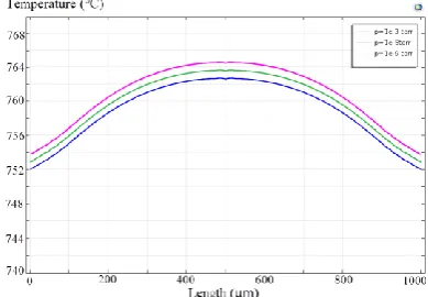
Figure 8 shows simulation results of the cathode thermal analysis. This figure shows that the temperature difference between the middle point and the end points is about 10℃ which depicts a 1.3% change in temperature. This indicates that the temperature is somehow uniform throughout the cathode. Figure 9 shows the cathode temperature changes as a function of gas pressure. This shape reflects the fact that the cathode temperature changes in the vacuum range of 10 -3 to 10-9 torr are only 2℃.
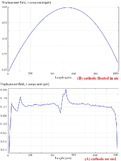
Under the condition that the cathode is suspended in the air, it will bend at 750℃. The buckling cathode affects its long-term performance and makes it slip from the base of the holder. In Figure 10, the buckled cathode is shown in the air. The buckling of cathode has a negative effect on its function as an electron emission section. In a cathode based on silicon oxide, no buckling occurs and only a thermal expansion occurs. In Figure 11, the mechanical analysis of the cathode based on silicon oxide and the cathode suspended in the air has been performed and comparison of their displacement in Z direction is shown.
This figure shows that the amount of displacement in a cathode that is suspended in the air is 27 times greater than that of the displacement based on silicon oxide.
Table 1 shows a comparison between the situation where the cathode is based on silicon oxide and suspended in the air. This table also shows that the silicon oxide-based cathode works better in some points of view than the cathode suspended in the air.
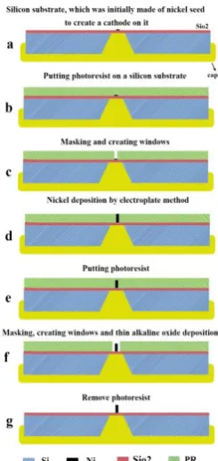
The proposed process for building a cathode can be one of the most important challenges in making this ionic gauge. In Figure 12, the steps of the cathode construction are proposed. The steps in this figure are shown and descriptions of each step is provided. In this figure, it is assumed that before this process, the nickel grain is formed on silicon oxide with a thickness of 1μm with different techniques [11, 12].
Figure 9. The dependence of the cathode temperature on gas pressure
Figure 10. Mechanical simulation of the cathode suspended in the air and its buckling
Figure 11. Mechanical displacement in Z direction (A) cathode based on silicon oxide (B) suspended in the air
TABLE 1. The heat dissipation Comparison A (cathode suspended in the air) and B (cathode based on silicon oxide)
A B
Power consumption 11mw 69.2mw
Temp. change along cathode 55℃ 11℃
Temp. change due to gas pressure change 10℃ 2℃
Max. vertical displacement 400μm 28μm
Max. stress N/m^2 5.5×10⁹ 4.5×10⁹
Also, a U-shaped cavity should be created next to the cathode, which is not included in this figure.
4. IONIZATION SIMULATION AND SENSITIVITY
To evaluate the performance of ionization in the proposed scheme of this paper, the Charged Particle Tracing (CPT) simulation in COMSOL has been utilized and the output data were analyzed by MATLAB.
Figure 12. The proposed process for implementation of cathode
Figure 13. The average velocity of electrons in the path of motion from the cathode to the anode
The electrons in the electric field, resulting from 30v potential difference will have 30ev energy. In this case, the electrons energy will be low and the probability of ionization of atoms will also be very low [8]. Electrons in the space between the collector and the anode electrodes with the energy of 120ev reach the maximum speed. The electrons with energy of 120ev have a high chance of ionization of atoms. According to Figure 13, the average speed of electrons moving in the ionization space reaches 4.5×10⁶ m / s.
The electrons accelerate as a charged particle in the presence of an electric field and reach to the speed of v quickly. This velocity is obtained from Equation (4) in which q is the electron and me mean mass of electrons.
2 1
. .
2 e
q v m v (4)
The frequency of the elastic collision of charged particles is shown in the relations (5) and (6) to calculate νelastic, which is the number of collisions per unit time. In these relations, Nd is the density of the gas atoms, σelastic is the elastic collision cross section, and is the particle relative velocity to the velocity of the atoms of the gas.
According to Equation (6), particle relative velocity depends on the mass of particles mp, the velocity of the particles v, the mass of atoms mg, the particle relative velocity to the mass reference g, the relative velocity of the sectional collision g' and the uniform random distribution unit vector R [20, 21].
( )
elastic d elastic
p
p g
v N v
m
v v g g
m m
(5)
, g
g v v g g R (6)
In Equation (6) which is related to an elastic collision, if the electron specification is considered as a particle, the relationship will be much simpler. In this formula, the electron mass is much smaller in comparison to the gas atoms, and in turn is faster, so mp<< mg and v>>vg. Under these conditions, instead of v', v can be replaced by the velocity of the electrons. The electron velocity is calculated as 2×10⁶ with 30v potential difference between cathode and collector. The electron velocity is calculated as 6.4×10⁶ with 120v potential difference between collector and anode. Hence average velocity of electrons in ionization space are calculated as 4.2×10⁶. In the speed of electrons, the elastic collision frequency of the relation (5) is calculated by determining the Nd for nitrogen gas at a vacuum pressure of 5×10⁻⁴ torr, and the σelastic in 120ev is obtained from reliable sources [4, 8, 13].
The ionization frequency similar to the elastic frequency is determined in the Equations (7) to (9). The only difference is in the value of g', which results in an energy loss after the collision of ΔE. In this theoretical relation, the approximation mentioned in the elastic collision can also be used [14].
( )
ionization d ionization
p
p g
v N v
m
v v g g
m m
(7)
,
g
g v v g g R (8)
2 ( )
. p g
p g
E m m
g g g
m m
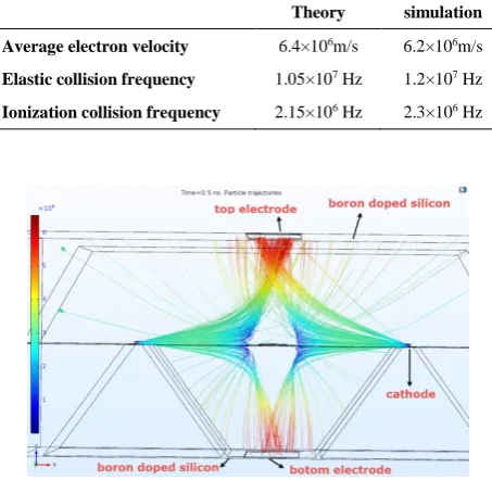
In Table 2, the values of v, νelastic, and νionization are summarized in simulation and theory. This table shows that there is a good match between the results of the theory and simulation.
Figure 14 shows the simulation results of CPT for the motion of electrons in the ionization environment. This figure shows simulation, as a useful tool for our design, which does not consider ionization and elastic collisions and is used to obtain the length of the paths for the electrons, as well as their energy and speed.
In this figure it is seen that the electrons leave hot cathode with the potential of 30V and accelerate towards the collector with the potential of 0V. Also, the electrons enter the ionization environment with 30eV energy and then accelerate towards the anode electrodes which contain 120V potential finally achieving the energy of 120eV.
Achieving high sensitivity is one of the main goals in the design of ionization configurations. The sensitivity coefficient S in Equation (2), depends on the mean value of the motion path of the electrons, l and the ionization cross section σi (Where σi is the energy of electrons and reaches its maximum in energy 100eV [7, 8]). In this paper, the l × σi function is defined as the determinative factor for achieving high sensitivity in an ionization gauge. In l × σi , the coefficient l is a function of the specifications and the physical dimensions, and σi is the electrical characteristics of the ionic vacuum gauge. One can obtain l by means of CPT simulations like the one shown in Figure 14 along with the analysis of output results.
TABLE 2. Elastic collision frequency and ionization collision frequency and average electron velocity in theory and simulation at 5×10⁻⁴ torr
Theory simulation
Average electron velocity 6.4×10⁶m/s 6.2×10⁶m/s
Elastic collision frequency 1.05×10⁷ Hz 1.2×10⁷ Hz
Ionization collision frequency 2.15×10⁶ Hz 2.3×10⁶ Hz
Figure 14. CPT simulation and electron motion in simulation environment
In addition of the mean value for the motion path of the electrons, the average energy of the electrons is also obtained. With the average energy of electrons, the σi function can be obtained using valid data sources [8, 13, 15].
The width of the anode is one of the parameters which can affect the performance of the MEMS gauge. To obtain the appropriate dimensions for the anode electrode, CPT simulation along with the analysis of its results are used by MATLAB. With these results, we can obtain the mean average motion path of the electrons and their average energy. With the help of average energy of the electrons, the ionization cross section σ will also be known. The l × σi function shows the efficiency of ionization vacuum gauge. This function is shown in Figure 15 in terms of the width of the anode electrode. As figure illustrates, the width of the anode electrode with 200μm provides the best performance for the MEMS ionization vacuum gauge.
If the elastic collision and ionization collisions become active in CPT simulation (see Figure 16), then in such condition some of the electrons will ionize the gas atoms and produce positive ions. The ions produced in the ionization environment are absorbed by the collector with a potential of 0V, and the electrons will also be absorbed in silicon cover and silicon substrate. The divergence of electrons from their paths is mostly due to an elastic collision. This is due to the multiplicity of the elastic collisions cross section relative to ionization.
Figure 15. Diagram of l×σi as a function of anode plate width
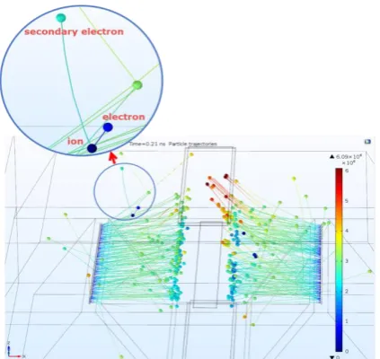
Figure 17 shows the simulation result of ionization and elastic collisions. In this figure, elastic collisions, ionization, positive ion production, and secondary electron are determined. Positive ions have very low velocity due to their high mass compared to the electrons and can be distinguished from electrons.
By means of the number of ions produced and absorbed in the collector, the sensitivity coefficient can be calculated.
In this paper, (10) has been used to calculate the MEMS ionization sensitivity coefficient. In this relation, the number of ions collected by the collector and the electrons emitted by cathode at the specified vacuum pressure is used to calculate the sensitivity. For example, in the pressure of 10-3 torr and 10,000 electrons emitted by the cathode, two positive ions are produced. In this condition, and according to (10), the sensitivity coefficient is 0.2 1/torr.
1
number of collected ion
S torr
number of trajected electron P
(10)
Equation (1) is used to obtain the measurable minimum pressure in the proposed ionization vacuum gauge. In this relation, the cathode electron beam current must be determined. The cathode is a nickel metal with a thin layer of alkaline oxide over it. The work function of the nickel metal is reduced to 1.1eV when the alkaline oxide layer is deposited on it. The cathode current density can be obtained by the Richardson relationship [10]. With the 1.1eV work function for the cathode, at 750 ℃, the current density is J≌ 5 A/m2. With the cathode dimensions specified in Figure 7, the cathode current will be 0.1μA. Equation (1) is rewritten for measurable minimum pressure condition in Equation (11).
Figure 17. CPT simulation of ionization and elastic collision
min min
C e
I S P I (11)
ICmin is very small in ultra-low vacuum pressures, making its measurement difficult. At present, the smallest electric current that can be measured is 0.1 fA11. Given these circumstances and the sensitivity
coefficient of 0.2, the minimum measurable vacuum pressure obtain is 5 × 10⁻⁹.
5. CONCLUSIONS
The idea of MEMS type hot cathode ionization vacuum gauge without the use of anode network (grid) was presented in this paper. With this idea the implementation of ionization vacuum gauge with no X-ray limitations can be achievable. The structure consists of a silicon cover and a silicon substrate in which the collector and the cathode were located in silicon substrate. The cathode design is in accordance with MEMS technology and works at 750°C. The design of the cathode is in away that the temperature is somehow constant throughout it and changes only by 1.3%. The cathode in the measuring range is independent of the vacuum pressure variations and its temperature changes only by 2℃. In this paper, a new idea was proposed for creating an anode network to accelerating electrons. The electrical and thermal simulations showed that the design has a power consumption of 69.2 watts. Simulations for ionization collisions and elastic collisions have been performed for the proposed design which resulted in the sensitivity coefficient of 5×10⁻⁹ torr. The proposed design has the benefits of shrinking, having the capacity for mass production, being able to integrate with other MEMS components, and even integrated circuits. In this paper, it was shown that the proposed design has very low power consumption, works at low temperatures, and has no X-ray limitations.
6. REFERENCES
1. Zhang, L.-M., Jiao, B.-B., Yun, S.-C., Kong, Y.-M., Ku, C.-W. and Chen, D.-P., "A cmos compatible mems pirani vacuum gauge with monocrystal silicon heaters and heat sinks", Chinese
Physics Letters, Vol. 34, No. 2, (2017), 1-4.
2. Piotto, M., Del Cesta, S. and Bruschi, P., "A compact cmos compatible micro-pirani vacuum sensor with wide operating range and low power consumption", Procedia Engineering, Vol. 168, (2016), 766-769.
3. Grzebyk, T. and Górecka-Drzazga, A., "Mems type ionization vacuum sensor", Sensors and Actuators A: Physical, Vol. 246, (2016), 148-155.
4. O'Hanlon, J.F., "A user's guide to vacuum technology, John Wiley & Sons, (2005).
5. Grzebyk, T., Górecka-Drzazga, A., Dziuban, J.A., Maamari, K.,
An, S., Dankovic, T., Feinerman, A. and Busta, H., "Integration of a mems-type vacuum pump with a mems-type pirani pressure gauge", Journal of Vacuum Science & Technology B, Nanotechnology and Microelectronics: Materials, Processing,
Measurement, and Phenomena, Vol. 33, No. 3, (2015),
03C103.
6. Pasandi, A., Afrang, S., Dowlati, S., Sharafkhani, N. and Rezazadeh, G., "Study of volumetric flow rate of a micropump using a non-classical elasticity theory", International Journal of
Engineering-Transactions C: Aspects, Vol. 31, No. 6, (2018),
986-996.
7. Suginuma, S., Hirata, M. and Kobata, T., "Simulation of relative sensitivity coefficient of bayard-alpert gauge Journal of the
Vacuum Society of Japan, Vol. 59, (2016), 156-159.
8. Kim, Y.-K. and Desclaux, J.-P., "Ionization of carbon, nitrogen, and oxygen by electron impact", Physical Review A, Vol. 66, No. 1, (2002), 1-12.
9. Jiaqi, W. and Jun, Y., "Fabrication process and electro-thermal modeling for the cathode of the cmos-compatible hot-filament vacuum gauge", Key Engineering Materials, (2015).
11. Salarvand, A. and Poursaeidi, E., "Comparison of properties of ti/tin/ticn/tialn film deposited by cathodic arc physical vapor and plasma-assisted chemical vapor deposition on custom 450 steel
substrates", International Journal of
Engineering-Transactions A: Basics, Vol. 29, No. 10, (2016), 1459-1468.
12. Azadi, M., Iziy, M., Marbout, A. and Rizi, M., "Investigation of the heat treatment effect on microstructures and phases of
inconel 713c superalloy", International Journal of
Engineering-Transactions A: Basics, Vol. 30, No. 10, (2017),
1538-1544.
13. Itikawa, Y., "Cross sections for electron collisions with nitrogen molecules", Journal of physical and chemical reference data, Vol. 35, No. 1, (2006), 31-53.
14. Humphries, S., "Charged particle beams, Courier Corporation, (2013).
15. Tämm, K., Mayeux, C., Sikk, L., Gal, J.-F. and Burk, P., "Theoretical modeling of sensitivity factors of bayard-alpert
ionization gauges", International Journal of Mass
Spectrometry, Vol. 341, (2013), 52-58.
Design and Simulation of Hot Cathode Ionization Vacuum Gauge with no X-Ray
Limitations
S. Mohammadzadeh Bazarchi, E. Abbaspour Sani
University of Urmia, Faculty of Electrical and Computer Engineering, Electronic department, Urmia, Iran
P A P E R I N F O
Paper history:
Received 7 April 2018
Received in revised form 1 July 2018 Accepted 17 Auguest 2018
Keywords:
MEMS Ionization Gauge MEMS Vacuum Sensor Hot Cathode Ion Gauge Vacuum Pressure Sensor Ion Gauge X-Ray Limitations
هدیکچ
عون مرگ دتاک ینوی جیگ هلاقم نیا رد
MEMS
یم هئارا سکیا هعشا تیدودحم نودب و رط .دوش
داعبا رد ح
3
mm
4 / 1 × 8 / 0 × 4 / 2 و هدوب 0000 هدودحم رد یداهنشیپ حرط .تسا رتکچوک فراعتم عون زا ربارب
HV
و
UHV
ات
ءلاخ راشف لقادح 0
-10 × 5 یم روت یامد رد حرط دتاک .دیامن لمع دناوت 750
یتناس هجرد یم راک دارگ .دنک سنج زا دتاک
نآ حرط و هدوب لکین ط رد نآ یامد هک تسا یروط
حرط یفرصم ناوت .تسا یطیحم زاگ راشف زا لقتسم و تباث نآ لو
430 هیبش هلاقم نیا رد .تسا رتمک فراعتم عون رادقم زا ربارب و نویسازینوی دروخرب ,یکیناکم ,ییامرگ ,یکیرتکلا یزاس
همانرب طسوت کیتسلاا دروخرب
COMSOL5
یم ماجنا هیبش زا یجورخ یاه هداد .دریگ یزاس
COMSOL
طسوت همانرب
MATLAB
یم لیلحت هیبش جیاتن زا .دوش تمسق داعبا باختنا و دتاک حرط یارب یزاس
یم هدافتسا رگید یاه زا .دوش
هیبش جیاتن تیساسح بیرض یزاس
1/torr
2 / 0 لصاح تسا هدش
.
doi: 10.5829/ije.2018.31.11b.12
10. Braithwaite, N.S.J., "Introduction to gas discharges", Plasma
Sources Science and Technology, Vol. 9, No. 4, (2000),
![Figure 1. Structure of the conventional ionization vacuum gauge and its external circuit [8]](https://thumb-us.123doks.com/thumbv2/123dok_us/24266.2002662/3.595.85.251.591.717/figure-structure-conventional-ionization-vacuum-gauge-external-circuit.webp)