Creative Space
Journal homepage: https://cs.chitkara.edu.in/
Pushing Limits of Leanness in Japanese Architecture: Modern Interpretations of the Frame
Structure through Collaboration of Japanese Architects with Structural Engineers
Takashi Ono
Chitkara School of Planning and Architecture, Chitkara University, Punjab, Rajpura, India
Email:[email protected]
ARTICLE INFORMATION ABSTRACT
Received:August 23, 2017 Revised: October 30, 2017 Accepted: November 12, 2017
Published online: January 01, 2018
The purpose of this research paper is to clarify the design intentions and methodology behind the experimental application of the Frame Structure by some contemporary Japanese architects through collaboration with structural engineers. The ‘Frame’ is the simplest of structure systems, but was applied to iconic structures such as the Parthenon and Le Corbusier’s Dom-Ino House, each example expressing artistic concepts and technical skills of the concerned era. One of the recent concepts seen in 21st century modern Japanese architecture is the ‘pursuit of transparency and thinness’. This is especially true of SANAA, are presentative group of architects, who – in close collaboration with structural engineers – pursue the quality of extreme thinness in columns and roofs, creatively exploring new methods of using framed structures. This paper focuses on three such projects that exploit the structural aspects of frame construction and, makes an attempt to understand the architects’ intention behind the designs. It presents an analysis of the contemporary interpretation of the traditional frame structure, used by the architects to apparently dissolve the material presence of the building and make it become part of the surroundings. These innovative attempts, made possible through collaboration between architects and structural engineers, signify one of the significant expressions of modernity in Japan.
Keywords:
Japanese modern architecture, Frame structure, Structural Engineer, Thinness
DOI: http://doi.org/10.15415/cs.2018.52005
1. Introduction
Since ancient times in Japan, it is common to find buildings based on timber frame structures, with the columns supporting compressive forces and, the beams and floor slabs bearing the bending moment. Since Japan is highly prone to earthquakes, these traditional frame structures also exhibit remarkable anti-seismic structural knowledge and construction techniques. Most traditional timber frame structures were designed with standard-sized, heavy columns and beams, which restricted the sizes of interiors and created sharp divisions between interior and exterior spaces. In recent years, however, some architects in Japan, with support of the structural engineers, have attempted a modern interpretation of the traditional frame, using new materials for challenging limits of the leanness and spatial rigidity imposed by traditional frame structures. The achievements have given rise to a new, state-of-the art contemporary trend in the country.
An ancient prototype of the frame structure is the Parthenon, the monumentality and construction methods of which reflect the essence of the advanced technology of those days. There is also the other iconic example of
Modern architecture – the ‘Dom-Ino House’ designed by Le Corbusier (1887-1965) in 1914, the architecture of which set a new trend during its time, with a decisive shift of both the artistic and the technical paradigm seen in the previous buildings. Contemporary architects in Japan, with the collaboration of structural engineers, have instituted yet another advancement of the Frame, integrating aesthetics and technology to accomplish new limits of ‘leanness in architecture’. The purpose of this research paper is to present an overview of these contemporary projects, primarily focusing on the designers’ re-interpretation of the frame structure as a reflection of Japanese modernity.
characteristics essential for analyzing frame structures. In addition, it is also notable that Ar. Ishigami and Er. Konishi, who designed KAIT Workshop, respectively trained under SANAA and Er. Mutsuro Sasaki during the time the first two projects were being designed. It is thus, that they have the same consistent idea, having inherited it from SANAA and Er. Sasaki.
Figure 1. Park Café (1998) at Municipal Park in Koga (Source: Márquez, F. and Levene, R., 2005, p33).
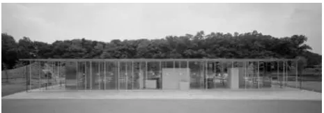
Figure 2. Ferry Terminal (2005) in Naoshima (Source: Márquez, F. and Levene, R., 2008, pp.104-105).
Figure 3. KAIT Workshop(2008) at Kanagawa Institute of Technology (Source: Márquez, F. and Levene, R., 2015, pp.184-185).
The methodology of this study is as follows: The first step is to describe how the frame structure was captured from the ancient times and transferred to modern architecture, as well as what values was found in it. This part will also explain the kind of collaboration that then existed between the architect and the structural engineer, and, the characteristics of the architecture that was born as a result of the collaboration. The second part will focus on the three contemporary projects, Park Café and Ferry Terminal Naoshima designed by SANAA and, KAIT Workshop designed by Ar. Junya Ishigami. The projects will be discussed from the view points of planning and structural design. The main research materials are the sketches and drawings of the three building projects. Simultaneously, the research also refers to their structural discourses. There are no preceding studies that have discussed the vision of these Japanese architects
using a structural design approach. Also, knowledge of the contemporary Japanese frame structure, which has been designed and executed by collaboration of the architect and the engineer, has never been shared out of Japan.
2. Innovation of the Frame Structure
Before specific analysis of three cases, first of all, this section discusses the understanding and the history of the frame structure of Japan.
2.1 Understanding the Frame Structure and the
Meaning of the Appearance of the Parthenon in
Ancient Greece
Er. Mutsuro Sasaki states, “I felt that the frame structure is artificial and tectonic” (Mutsuro, 2017). Further, he has also analyzed the original thought that was seen at the Parthenon. The frame system is the simplest structure, placing the beam as a horizontal member and the column as the vertical member. It is the origin of the moment-resisting system in which the column bears the compressive force and, the beam carries the force by bending the member. The Parthenon is acknowledged as the masterpiece of this system. The Parthenon exemplifies a classical building, the column sizes of which were calculated both artistically and technically. For example, the original, authentic elements of which each column was constructed were eleven cylindrical drums. While the height of each drum is equal (90 cm), the bottom ones are of 1.96m diameter and, the top ones of 1.46m diameter, the drum getting thinner as it goes up (Yoshiyuki and others, 1993).The Parthenon – following the latest technology then available – was thus designed artificially to achieve desired visual effect as well as structural treatment. In Sasaki’s words, “I think that not only geometry and aesthetics were important but also clear and reasonable correspondence was done in the structural aspects such as strength and stability” (Mutsuro, 2017).
Le Corbusier also appreciated the Parthenon. He later established the ‘Dom-Ino System’, which consisted of the reinforced concrete column and the slab (without the beam).What was revolutionary for the time was that the use of the frame allowed the buildings to be open, removing the load-bearing masonry walls that had, till then, closed all four sides of European buildings. This idea was sublimated later into sophisticated frame structures, such as are seen at the Lake Shore Drive Apartments (1951), designed by Architect Mies van der Rohe.
2.2 History of the Collaboration between
Architects and Engineers in Japan
Architect Kenzo Tange (1913-2005) and Er.Yoshiaki Tsuboi (1907-1990). Their collaboration started with ‘Ehime Prefectural Gymnasium(1953)’ and culminated in the ‘Yoyogi National Stadium (1964)’. Some other structural engineers, namely, Er. Matsui Gengo (1920-1996) and Er. Kimura Toshihiko (1926-2009), also appeared in those days and, established a unique approach for achieving large column-free spaces to replace the frame structure. The innovative structural systems created by the collaboration of architect and engineer dominated the character of the iconic buildings of those times. Initially, the timber frame as well as the space formed by frame structure was the main concern of architects and engineers. For example, even if ‘Kagawa Prefectural Office(1958)’, which is the work of Kenzo Tange and Yoshikatsu Tsuboi, is a frame structure constructed in reinforced concrete, the building reflects the Japanese traditional design, combining elements such as beams, columns as well as some typical details. Many similar examples of frame structures were constructed before the 1970s through collaboration between architects and structural engineers (Nobuyuki, 2014). As a consequence, symbolic and yet massive, bold architecture showed up in Japan. Such collaborative relationships were stalled after the 1970s. However, with the emergence of high-tech buildings, the situation in terms of the collaboration with structural engineers has been re-evaluated.
Around the turn of the century, in the 2000s, architects began the conscious pursuit of transparency and thinness in architecture, for example in the design of ‘Kasai Rinkai Park View Plaza Rest House (1995)’and ‘Sendai Mediatheque (2000)’. The Sendai Mediatheque assumes especial significance as an innovation of the ‘Dom-Ino system’, something that Architect Toyo Ito (b.1941) mentioned as a new vision of the rigid frame structure. The projects that have been focused on in this research paper were born as the next stage of the systems devised for above context.
3. Frame Structures Created by Collaboration
Between SANAA and Mutsuro Sasaki
Comparing the analysis of table 1 & 2 on the three cases, this section focuses on the frame structure by SANAA and Er. Mutsuro Sasaki.
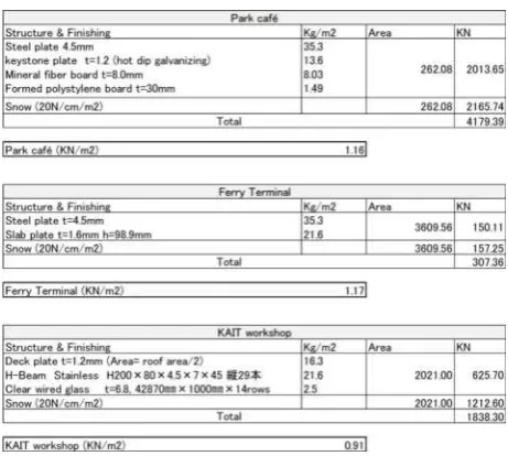
3.1 Explanation of Analysis of Tables 1 & 2
Table 1 shows the structure and finishes of the roof, along with the load per square meter supported on the columns with respect to each of the three projects. All values are calculated theoretically. Table 2 shows three things:(1) The vertical load for a single column, (2) The compressive force of the single columns supporting the roof, and, (3) Thebuckling load based on the Table 1. Although the forces acting on buildings can be generally divided as vertical force and the horizontal force, this Table 2 is about the vertical force with especial respect to each project. As per the bylaws of Japan, the vertical force is a combination of dead load (weight of building roof and slab) and, the snow load (different for each region). All the three projects comprise a single story, so that the dead load comprises only the weight of the roof. After having considered the dead load and the snow load, the theoretical value of the bearing load was calculated by Euler’s Column Formula. As regards the material strength of compression, the minimum strength value is decreed by the bylaws.
Table 1. Structure and finishing with respect to three projects.
Table 2. Comparison with single column between vertical load(1) and buckling load(3).
3.2 The Case of the Park Café (1998)
3.2.1 Overview of the Project
also exterior spaces. The spaces of the Café and Terraces are separated by glazing and sliding doors, so that when glazed sliding door opens the interior space suddenly merges with the outside and gets connected to the space of the terrace.
3.2.2 Understanding Structural Aspects through Drawings and Sketches
Figures 4 & 5 show the plan and axonometric drawing of the Park Café, which is a steel structure. The floor area is 262sq.m. The overall form of the building is a cuboid, with its long axis oriented in the east-west direction. The building consists of a flat, thin roof (just about 100mm thick), sized 25.2m × 10.4m. Approximately one hundred steel cylinder columns, each 60.5mm in diameter, 6mm thick and 2.7m high, are posted on a rigid grid of 1.2m × 1.2m. However, unlike what is seen in the case traditional frame structures, the columns of this building are not necessarily located at each intersection of the grid, but are randomly set up at about half of the 189 intersection points. This leads to the creation of some large, column-free spaces that can be used for a variety of purposes, such as meeting space for visitors.
Figure 4. Plan of Park Café (Source: Traced by author based on following reference;Nobuyuki, 1998, p.172).
Figure 5. Axonometric drawing of Park Café (Source: Modeling by author based on the drawings of the following reference; Nobuyuki,1998, p.172-182).
For structural analysis, it becomes necessary to consider forces in the vertical direction as well as the horizontal direction. We will first take up the discussion regarding the compressive force and buckling load of single column with respect to the vertical force. In the case of the three projects discussed in this paper, the compressive force is not important because, as shown in Table 2, the material strength of steel can support it adequately. But, discussion on the buckling load is specially required due to the thinness of the columns. According to Table 2, there is sufficient proof of stress of the single columns, with compressive force as well as the buckling load posted on the 1.2m × 1.2m span. In fact, theoretically speaking, even the 3.6m × 3.6m grid, which is 9 times larger in area, can be supported. However, why the architects have not done so, is because the smaller-sized grid is so dictated by their intention of creating ‘a space like a forest’ within the interior of this building. While some columns are clustered (as the trees in a forest), some others are thinned out. Then, the architects create some larger spaces, like a forest clearing, for taking rest and so on. If the architects merely wanted to pursue the non-materiality of the columns, they could have theoretically designed thinner columns. However, the intention was not only pursue the structural and material limit of thinness, but also to create ‘a space like a forest’, reflecting the landscape of the exterior.
Figure 6. Resistant walls with the stainless steel plate reflecting surrondings (Source: Márquez, F. and Levene, R., 2005).
would seem to dissolve. It needs to be emphasized that due to their limited, thin dimensions, the columns and roof did not dominate the landscape and appeared as part of the surroundings, but the horizontal resistance walls had necessarily to be thicker and, thus, need special treatment.
3.3 The Case of the Naoshima Ferry Terminal
(2005)
3.3.1 Overview of the Project
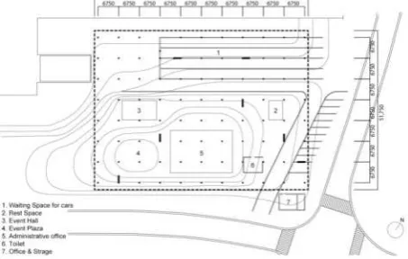
The building is located on a small island in the Inland Sea of Japan and functions as the entrance foyer for tourists and residents (Fig. 2). It is a place where passersby, cars and boats go and come. An extremely thin roof covers a variety of spaces – cafes, waiting spaces, tourist information centers, event halls, etc. – which are placed in scattered glass boxes. Outside of the glass box are semi-covered spaces, an event square, a waiting space for cars, a parking lot, a handling space and, a bus drop-off point. Various people gather under the roof of this building, waiting for the ferry, relaxing at the cafe, for riding a ferry by car. According to the situation, it is possible to open the public space freely.
3.3.2 Understanding the Structural Aspect through Drawings and Sketches
Figures 7 & 8 show the plan and axonometric drawing of this building, which – like the Park Café - is also a steel structure. The building measures 69.75m × 51.75m, and has a covered floor area of 3640sq.m. A simple building, with a maximum height of 4.6m, it consists of a thin roof merely 154.5mm thick. Thin cylinder columns (diameter of 85mm) are posted on a grid of 6.75m × 6.75m. Under the roof, some glass boxes and semi-open spaces are located on the gently sloping floor. Incidentally, the glass boxes that form the interior space cannot contribute it structurally. As in the case of the Park Café in Koga, this building also requires individual consideration of the forces in the vertical and the horizontal directions. First, according to the values shown in Table 2, the buckling load is slightly higher than the vertical load (unlike the Park Café), so that both the span and size of the columns are adequate for the maximum height of 4.6m.
Initially, Municipal corporation required small ferry terminal sized 600sq.m., primarily to save construction cost while satisfying basic requirements (Nobuyuki, 2006). The architects, however, proposed the 3,600sq.m building, which is six times larger than that proposed, because they wanted to present a gathering place for visitors and residents and, create a single roof which could not only shelter users from sun and rain, but also serve to revitalize the town. In order to realize this proposal without much additional cost, the architects proposed that the building
be constructed with a thin roof as well as thin and fewer columns, thereby also giving shape to their intention of dissolving the materiality of the building. Avoiding the limitation imposed by columns on the span, the architects reduced the number of columns as much as possible. The building has been established adopting thin columns, and ensuring as long a span as possible. As for the horizontal resistance force, as in the case of Park Café in Koga, there are seven resistance walls (each measuring 150mm × 2.4m). The mirrored finish of the walls reflects the surroundings and reinforce the architects’ intention of dissolving their existence. Once again, it is a means to integrate the building with the natural landscape of the site.
Figure 7. Plan of Naoshima Ferry Terminal (Source: Traced by author based on the following reference;Márquez, F. and Levene, R., 2008,p.110).
4.1 The Case of the KAIT Workshop (2008)
4.1.1 Overview of the Project
KAIT Workshop, located on the campus of the Kanagawa Institute of Technology, was planned as a place where students could easily experience the fun of making things. Because it is a glass-covered building, the interiors can be seen by outside students as well (Fig. 3). Thus mutual influence between the activities of students inside the building and those of other students observing from the outside can be expected.
4.1.2 Understanding the Structural Aspect through Drawings and Sketches
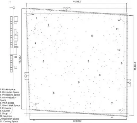
Figure 9 & 10 show the plan and axonometric drawings of this building. The building, with a floor area of 1,989 m2 (approx. 47m × 43m), is diamond shaped in plan
and has a steel structure. The crucial feature of KAIT Workshop is that there are no resistance walls and braces to resist horizontal force of earthquakes. It only consists of 305 steel frame columns of different sizes, for example 90mm × 57mm, 155mm × 20mm, etc., with the inter-columnar spans arranged to respond to the orientation and size of the columns, which are placed according to the function of the corresponding activity space, though in an apparently random visual order.
Figure 9. Plan of KAIT Workshop (Source: Márquez, F. and Levene, R., 2015, p.194, adding the dimensioning by author).
The Architect took advantage of the characteristics of the thin and wide steel frame columns (Fig. 11) and, ingeniously placed them in the plan, intending that the columns should make the wall recognizable with their wide
surfaces lining up from one side. At the same time, the arrangement also allows an open view for the users, giving them a sense of unity when the thin surface of the columns line up from another side.
Figure 10. Axonometric drawings of KAIT Workshop analizing the structral elements (Source: Nobuyuki, 2014, p.30).
surroundings and dissolve the materiality of the building, the frame structure was so designed as to thin down the columns to the maximum limit, make the roof very light and, to remove the walls that would block the outside view.
Figure 11. Material strength of the flat bar (Source: Mutsuro, 2017, p.58 ).
Figure 12. Construction procedure of the system adding tension at the time of construction (Source: Nobuyuki, 2014, p.31).
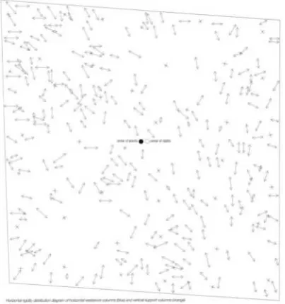
Figure 13. Direction and strength of the horizontal columns shown by blue and vertical support columns shown by red (Source:
Source: Nobuyuki, 2014, p.31).
5. Architecture Achieved by Collaboration of
Architect and Structural Engineer – Pursuit of
Thinness in Frame Structures
As mentioned before, the frame structure is artificial and tectonic and, that both in the case of the Parthenon and
the Dom-Ino house, the then latest technology, including construction materials and methods, had allowed innovations in a frame structure. Due to an aesthetic pursuit of thinness, the frame structure advanced towards the maximum possible dissolution of its presence, while also removing the sense of frame to enable integration of interiors with the surroundings. The path towards this achievement included use of thin columns and a thin roof needed for blocking sun and rain. Even when walls were used as anti-seismic measures, these were finished with reflecting materials (such as mirror-finish stainless steel) in the attempt to dissolve the wall’s presence.
Two types of spaces there can be seen in this analysis – one is the space like a forest, the other is the free space under the roof, made so by reducing the number of columns. In other words, the difference in the buildings depends on whether or not the architect has used a column for crafting/creating the space. In either case, since unconventional designs were evolved, the architect could no longer ensure building’s structural rationality without input and support from structural engineers.
As can be seen in the case of the third project, the KAIT Workshop, even though using a frame structure, the design process required computer simulation for a series of ‘trials and errors’, along with analysis and experiments, to ensure the rationality of the structure (Mutsuro, 2017). As has been mentioned in Section 2, the contemporary frame structure, designed and realised jointly by Architect and Structural Engineer, is more sophisticated both artistically and technically. This project demonstrates that collaboration between architects and structural engineer can produce masterpieces of ‘pursuit of transparency and thinness’ that also demonstrates ‘structural rationality’.
6. Conclusion
The history of collaboration between architects and structural engineers in Japan goes back to about 60 years. Initially, this collaboration led to massive, bold and symbolic architecture. However, in the 2000s, began the ‘pursuit of transparency and thinness’, resulting in buildings seeking to extend the limit of leanness. This is seen through the three projects that have been focused on and analyzed in this paper. The projects established by SANAA, Junya Ishigami and Mutsuro Sasaki have actually accomplished an extreme transparency and thinness of the frame structure. Needless to say, the realization of the architecture conceived by the architect could not have been possible without the major role played by structural engineers, including through computer-aided simulation.
sense, is the simplest of structures, easy to grasp through division into horizontal and vertical forces. Hence, it can be said that research analysis of the structural aspects is possible. Creative manipulations and innovative approaches to the use of the traditional frame structure is one of the aspects of modernization in contemporary Japanese architecture. As seen through the three projects studied in this research paper, dissolving the presence of the material members of the frame structure serves not only to eliminate the sense of framing of the building, but also integrates it with the surrounding environment.
References
[1] Márquez, F. and Levene, R. (eds.) (2005). El croquis N. 121/122 SANAA (Sejima + Nishizawa) 1998-2004, Madrid: El croquis Editorial
[2] Márquez, F. and Levene, R. (eds.) (2008). El croquis N. 139 SANAA (Sejima + Nishizawa) 2004-2008, Madrid: El croquis Editorial
[3] Márquez, F. and Levene, R. (eds.)(2015). El croquis N. 182 Christian Kerez Junya Ishigami. Madrid: El croquis Editorial
[4] Mutsuro, S. (2017). Structure/Tectonic/Architecture: Structural Vision of Sasaki Mutsuro (Japanese Title: Kouzo/Kouchiku/Kenchiku Sasaki Mutsuro no KouzouBijyon), Tokyo: Lixil
[5] Nobuyuki, Y. (ed.) (1998). JA31Space in detail III, Tokyo: Shinkenchiku-sha
[6] Nobuyuki, Y. (ed.) (2006). Shin-Kenchiku Dec., Tokyo: Shinkenchiku-sha
[7] Nobuyuki, Y.(ed.)(2014). JA95 Idea of Emerging Structural Designers, Tokyo: Shinkenchiku-sha [8] Yoshiyuki, M. and others (1993). An Experimental