Cite this article Nasiri Khalaji M, Afshari F, Kotçioğlu İ. Experimental and Numerical Investigation of Heat Transfer in Different Winglet- Surface in a Vertical Rectangular Duct. International Journal of Innovative Research and Reviews (INJIRR) (2018)2(1):16-24
Link to this article: http://www.injirr.com/article/view/2 Copyright © 2017 Authors.
This is an open access article distributed under the Creative Commons Attribution-NonCommercial-NoDerivatives 4.0 International License, which permits unrestricted use, and sharing of this material in any medium, provided the original work is not modified or used for commercial purposes.
International Journal of Innovative Research and Reviews
ISSN: 2636-8919 Website: www.injirr.com
doi:
Research paper, Short communication, Review, Technical paper
RE S E A R C H AR T I C L E
Experimental and Numerical Investigation of Heat Transfer in Different
Winglet- Surface in a Vertical Rectangular Duct
Mansour NASIRI KHALAJI
1,*, Faraz AFSHARI
2, İsak KOTÇİOĞLU
31 Ataturk University. Department of Mechanical Engineering, 25240, Erzurum, Turkey.
2 Erzurum Technical University. Department of Mechanical Engineering, 25240, Erzurum, Turkey. 3 Ataturk University. Department of Mechanical Engineering, 25240, Erzurum, Turkey.
*Corresponding author E-mail: [email protected]
HI G H L I G H T S
Today’s industry requires removal of high heat accumulation from small surfaces such as micro-processors, and higher convection heat transfer rates are needed.
Experimentally studying such systems are costly and due to interventions and uncontrolled factors results are not so reliable, therefore numerical studies and simulation software are of great importance.
Different fin geometries and arrangements for cooling of such systems are studied using Ansys fluent, and a 3-D model of the turbulent flow in an arbitrary system has been analyzed. While the max heat flow per fan power has been obtained with cylindrical fins, the narrow/wide flipped arrangement has been found to be more effective in terms of heat transfer rate.
AR T I C L E IN F O Received : 04.09.2018 Accepted : 07.12.2018 Published : 07.15.2018
Keywords: Heat transfer, Heat exchanger, Winglet,
Numerical simulation, ANSYS Fluent.
AB S T R A C T
One of the ways to increase heat transfer is to increase the heat transfer coefficient. The heat transfer coefficient can be increased by active and or passive methods. In addition to increas-ing the heat transfer surface area, the fins produced by usincreas-ing different structures increase the heat transfer by passive method by breaking the boundary layer. This paper presents the ex-perimental and numerical results of forced convection in a rectangular vertical channel. Ex-periments have been performed for three different fin shapes including, flat plate, cylindrical and diffuse (Narrow wide) (with the angle of θ = 60°) inside the wind channel. The obtained results are presented to show changes in Nusselt numbers and friction factor for all tested winglet types.
Furthermore, for each type of winglets, test results have been compared between winglets in the term of temperature distribution along the winglets. It has been concluded that, heat trans-fer coefficient can be improved due to from renewal as periodic of the boundary layer with effect, which of this winglets have particularly placed in the event of groups periodically contracting and expanding in the winglets. Basic conservation equations are solved in con-tinuous flow regime using three-dimensional simulation in the turbulent flow conditions by means of ANSYS Fluent as a CFD program based on finite volume method. the geometry that has the best heat transfer as a result of the experimental and numerical analyzes made is narrowly wide and then the flat plate and finally the cylinder is ordered to be over the cylinder.
Contents
1. Introduction ... 17
2. Experimental setup and test procedure ... 17
2.1. Calculation ... 18
3. Experimental results and discussion ... 19
3.2. Results and evaluation for numerical Analysis ... 21
4. Conclusions ... 23
Acknowledgment ... 23
References ... 23
1.
Introduction
Heat exchangers with different forms are widely used in the engineering, chemical industry and process industry, etc. as efficient heating and cooling apparatus. The subject of heat transfer enhancement is of serious concern in heat exchanger applications, which leads to saving in cost and energy. How-ever, important other parameters including, pressure losses, weight, compact designs and total price are also taken into account to design the desired and expedient heat exchangers. The mentioned items, motivate scholars to optimize the per-formance of heat exchangers and thermal systems over the existing designs [1].
Different channel and fin types were the subject of numerous valuable studies in the open literature. Heat transfer and flow structure in a rectangular channel with longitudinal wake [2], heat transfer in multiple parallel vertical channels with iso-thermal walls [3], were analyzed in detail. Taguchi method was used to optimize an exchanger design in a rectangular duct. The effects of Reynolds number, the ratio of the duct channel width to height, winglets length to the duct channel length and inclination angles of winglets was investigated. Nusselt and friction factor were presented as performance parameters [4, 5]. Briggs et al. studied the flow friction and heat transfer characteristics in six plain triangular plate-fin and five offset rectangular [6]. Different types of vortex gen-erator were used to analyze heat transfer and fluid flow struc-ture in a fluid passing channel [7, 8].
Heat transfer and pressure drop were studied experimentally for a new type of perforated surface heat exchangers in the range of Reynolds numbers lower than 3000 [9]. Caliskan et al. [10] investigated impinging jet array heat transfer in dif-ferent Reynolds numbers for a surface with V-Shaped Con-vergent–Divergent Ribs. Total Nusselt numbers were pro-vided as performance factor of test results [10]. Periodically converging-diverging tubes consisted of a succession of al-ternately converging-diverging conical sections were exper-imentally studied to determine fully developed heat transfer coefficients, pressure distributions, and friction factors. The oil-lampblack technique was used for flow visualization [11]. In the laminar flow, the converging-diverging channel was analyzed using discretized conservation equations for energy, mass, and momentum on a control volume as a finite difference solution [12]. Another numerical solution was employed by using a finite difference method in an array of vertical overlapping discrete plate segments in the natural convection conditions. It was revealed that the overlapping arrays enhances the heat transfer rate approximately 80–90% [13].
A CFD computer code was performed in another study by Sahin et al [14]. GAMBIT and Fluent software were used to mesh and analyze heat transfer rate of plate fin-tube heat ex-changers with seven different fin angles [14]. Fluent program was also used for heat transfer characteristics in a tube with circular cross-sectional rings. Five different rings spacing
was tested and compare in the range of Reynolds number 4475–43725 and the maximum overall enhancement of 18% was reported for Re = 15,600 [15].
2.
Experimental setup and test procedure
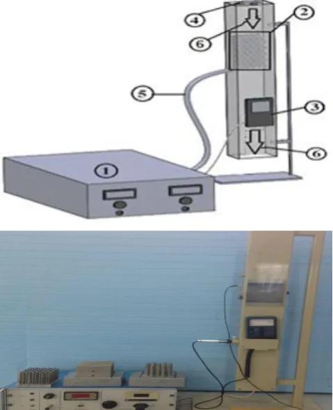
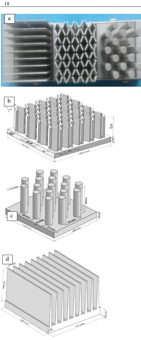
The schematic view and a picture of the stainless steel ver-tical channel with rectangular cross-section with 12 × 8 cm inner sides, length of 100 cm and the wall thickness of 1 mm are shown in Figure 1. In addition, schematic view of three different prepared fins (made of aluminum) is presented in Figure 2. One speedometer at the channel entrance was used to record air flow rate through the vertical channel and T-types (Copper/Constantan) thermocouples located on chan-nel inlet, outlet and wall surface of the test fins to measure the needed temperatures. All fin types are tested under four different heat fluxes and four flow rates including, 20, 40, 60, and 80 W at the velocity of 0.5, 1.0, 1.5 and 2.0 m/sec. The air flow rate can be controlled and adjusted by a manual valve installed in the power and control unit to approach the intended velocity.
The uniform heating power is supplied by DC electric heater connected to the lower surface of the fins. Regarding the temperatures and make ensure that the system is in the stable condition, measured data have been taken and recorded.
Figure 2 (a) Fins picture and schematic view. (b) Narrow wide surface, (c) Cylindrical diffuser, (d) Flat Plate fins
2.1. Calculation
In the present work, heat transfer rate is assumed to be in a steady state condition. In addition, according to previous re-search [16], radiation heat loss (approximately 3% of the in-put thermal energy) can be supposed to be ignorable and also consider that the test section is insulated (except for front-side), electrical power energy provided for heat transfer can be stated as,
𝑄̇=VI= (1)
convective heat transfer coefficient is given as,
(2)
bulk temperature of the fluid is,
(3)
Where A and T are heat transfer area of the surface and av-erage temperature of the surface respectively. It should be stated that the thermo-physical properties of the air have been determined at the overall bulk temperature. Average Nusselt number of heat transfer coefficient (h) can be calcu-lated as,
(4)
Here, λ is fluid local thermal conductivity and L is the length of the channel.
The Reynolds number based on the total flow rate at the inlet section is obtained by:
(5)
where and de are the average velocity and effective
diame-ter, respectively. For the used channel effective diameter can be calculated by the following equation,
(6)
where is the net volume of the channel and can be ex-pressed as,
( ) (7)
The channel friction factor can be computed along the test section by pressure loss, ΔP, as the following equation:
2
( ). . 2
m h
P f
U L
D
(8)
In this equation,
is density of is film temperature of the air and Um is the average velocity of the fluid. In the subjectsof strategies for heat transfer enhancement, enough attention should be paid to flow resistance, friction factor value and performance factor. Regarding the Nu number and friction factor, the performance factor of the experimented fins is evaluated to have an appropriate comparison of overall thermo-hydrodynamic performance among test fins. Perfor-mance evaluation criteria”, Ƞ, is written as following [17, 18],
Ƞ (9)
where f0 and Nu0 are the friction factor and Nusselt number
of the plain channel.
With the aim of validation, the obtained Nusselt number (Nu) and friction factor (f) of the plain channel have been compared to those correlations proposed in the literature. The empirical correlations for the plain channel are consid-ered to achieve Nusselt number and friction factor as follows [19, 20],
h .L
Nu
b
c
Nu = 0.023Re0.8 Pr1/3 (10)
Colburn correlation (for 104 ≤ Re)
Nu=0.023Re0,8Prn (n=0.3-0.4) (11)
Dittus-Boelter correlation (for 104 ≤ Re)
f=0.316Re-0.25 (12)
Blasius correlation (Re ≤ 20000)
f= (0.790 ln Re – 1.64)-2 (13)
Petukhovcorrelation (for 3000 ≤ Re ≤ 5×10⁶)
To compare the experimental results, experiments were per-formed using the same size, the different elements of the ex-perimental vane.
In this study, ANSYS Fluent 16 has been used to analyze the described problem that can be assumed to be 3-D model with turbulent flow. A schematic view of geometry with the anal-ysis domain has been shown in Figure 2. At this stage, the following assumptions are applied for air as test fluid in the derivation of continuity, momentum and energy equations, In this section, conservation equations including, Equations 14, 15 and 16 are given for mass conservation, momentum equation, and energy conservation respectively, as follows,
(14)
(15)
(16)
The CFD simulation has been analyzed by using k- RNG model with enhanced wall functions for the near wall treat-ment which can be expressed as,
(17)
(18)
(19)
In the present study, mesh validation analysis has been per-formed for the entire test region. It was revealed that the problem is converged in over 5*106 cells. The grid is well
concentrated close to the walls and fins to achieve precise results in the boundary conditions.
3.
Experimental results and discussion
The experiments on the surface before the wingless and rec-tangular channel, then the test system shown in Figure 1 and shown in Figure 2 with the experimental elements of differ-ent experimdiffer-ents carried out with speed and heat load. Aileron surface and body temperature measurements were made of three different points.
The specifications of the experimental vane elements in Fig-ure 2 are shown.in FigFig-ure 3, FigFig-ure 4 and FigFig-ure 5, with the temperature of the cooling fins, each fin to the height of a model given in exchange. Q heat of the system is given the
same amount for each model. As you can see the results ob-tained from the temperature value is evaluated in terms of shrinking-expanding channel temperature rise is higher than the others. This model shows that the heat transfer is better.
Similarly, Figure 6, Figure 7, Figure 8 and Figure 9, the graphs are examined, 0.5, 1.0, 1.5 and 2.0 m/s speeds for each test element 20, 40, 60 and 80 watts of heat load and the Reynolds number coefficient of friction between the ex-change were investigated.
Shrinking-expanding type was observed that a higher coeffi-cient of friction. Refers to loss of pressure in this too, is more than the others. The same way, Figure 10, Figure 11, Figure 12 and Figure 13 examined changes between Nu and Re numbers 20, 40, 60 and 80 watts of heat load was observed shrinking-expanding type better heat transfer takes place.
Figure 3 The plane is to natural convection finned plate fin length (L) - fin temperature exchange (T T
H )
Figure 4 For natural convection cooling fins, the length of the cylindrical vane plate (L) - fin temperature exchange (THT)
Figure 5 Shrinking-expanding vane diffuser for natural convection in plate length (L) - fin temperature exchange (T T
H )
30 50 70 90
0 20 40 60
T(
C
)
Fin Length L(mm)
20W 40W 60W 80W
30 50 70 90 110
0 20 40 60
T
(C
)
Fin Length L (mm)
20W 40W 60W 80W
50 60 70 80 90 100 110
0 20 40 60
T
(C
)
Fin Length L (mm)
Figure 6 U = 0.5, 1, 1.5, 2 m/s speeds for the Re - f exchange (20 W)
Figure 7 U = 0.5, 1, 1.5, 2 m/s speeds for the Re - f exchange (40 W)
Figure 8 U = 0.5, 1, 1.5, 2 m/s speeds for the Re - f exchange (60 W)
Figure 9 U = 0.5, 1, 1.5, 2 m/s speeds for the Re - f exchange (80 W)
Figure 10 U = 0.5, 1, 1.5, 2 m/s speeds for the Re - Nu exchange (20 W)
Figure 11 U = 0.5, 1, 1.5, 2 m/s speeds for the Re - Nu exchange (40 W)
Figure 12 U = 0.5, 1.0, 1.5,2 m/s for the Re-Nu exchange(60 W)
Figure 13 U = 0.5, 1, 1.5, 2 m/s speeds for the Re - Nu exchange (80 W)
3.1. Numerical Analysis
Heat exchange between two or more fluids at different tem-peratures is one of the most common processes in engineer-ing applications. The heat exchangers used for this change can be found practically in thermal power plants, chemical industries, heating, air conditioning, cooling installations, vehicles, electronic devices.
The correct sizing and fabrication of heat exchangers with a wide range of applications provide significant economies, especially for large heat loads. For this reason, it is aimed to manufacture heat exchanger with low loss and high effi-ciency. However, with this in mind, the most favorable solu-tion must be found by adding some other factors such as se-lection of suitable materials, operating costs, noise, system stability, etc.
Improving the performance of heat exchangers; at the exit of the heat exchanger in the given operating conditions, the temperature difference between the cold fluid and the hot fluid is reduced as much as possible. It is one of the preferred methods to increase the heat transfer coefficients of the fluids to reduce this temperature difference. Increasing the heat
25 35 45 55 65
0 5000 10000 15000
f( 1 0 ^ -3) Re
Narrow-Wide Cylendrical Flat
20 30 40 50 60
0 5000 10000 15000
f (1 0 ^ -3) Re
Narrow-Wide Cylendrical Flat
10 20 30 40 50 60
0 5000 10000 15000
f (1 0 ^ -3) Re
Narrow-Wide Cylendrical Flat
20 30 40 50 60
0 5000 10000 15000
f( 1 0 ^ -3) Re
Narrow-Wide Cylendrical Flat
0 20 40 60 80
0 5000 10000 15000
Nu
Re
Narrow-Wide Cylendrical Flat
20 30 40 50 60 70 80
0 5000 10000 15000
Nu
Re
Narrow-Wide Cylendrical Flat
20 30 40 50 60 70 80
0 5000 10000 15000
Nu
Re
Narrow-Wide Cylendrical Flat
20 30 40 50 60 70 80
0 5000 10000 15000
Nu
Re
transfer coefficients can be achieved through active or pas-sive methods of heat transfer enhancement techniques. Meth-ods such as rotating the surface, vibrating the fluid, using mechanical auxiliary elements, mixing the flow with the me-chanical parts, forming the surface vibration, forming the electrostatic fields in the flow medium; Examples include passive surface treatment of the surface of the heat transfer surface, surface replacement, twisted tape fragments, screw type turning pieces, winding wires, guide wings, flow rolling propellers, insertion turbulence generators and enlarged sur-faces, known as the fin heat exchanger, has many varieties.
Increasing the turbulence intensity of the flow medium by increasing the contact surface in the flow medium is used for the purpose of facilitating the disintegration and re-formation of the boundary layer by placing it comfortably in the flow medium and increasing the heat transfer area. In addition to experimental studies, there are many studies in the literature where numerical methods are used to obtain a numerical ap-proximate solution instead of a definite analytical solution. Sahin et al. [14] studied the heat transfer increase and pres-sure drop in seven different wing angle flat plate finned tube heat exchangers. Three-dimensional numerical computa-tional technique Numerical simulation using CFD code Flu-ent has been performed. Ozceyhan et al. [15] studied numer-ically the heat transfer rate to the boron with circular section ring. The plate heat exchanger in the experimental system was analyzed at different temperature and flow rates. The op-timum temperatures of the fluids circulating in the heat ex-changer in different operating conditions were determined and the system was analyzed by the second law and the AN-SYS computer program.
3.2. Results and evaluation for numerical Analysis
The effects of heat transfer with three different geometries placed on the heat exchanger have been investigated numer-ically. The results of the analysis performed with Ansys Flu-ent, a computational fluid dynamics package program; Ra-ther than establishing high-cost and long-time test systems, three-dimensional complex flow problems can be solved in a short time with high-performance calculations with com-putational fluid dynamics.
When the temperature distributions in the numerical calcula-tions are examined, the temperature difference at the inlet and outlet will be measured until the rise of the air is 2-1.5-1-0.5 m/s.
The conjugate heat transfer analysis of fins is carried out by using commercial available FLUENT® software and
turbu-lence module is used to account for turbuturbu-lence phenomenon.
Figure 14 Plate position
Figure 16 In Plate fins Temperature, Velocity and Pressure distribution for V=0.5 – 1 – 1.5 – 2 m/s
Standard k-ε model is used for turbulence model. As the first step of the present study, the CFD results have to be validated against analytical values or experimental values or previous literature data. In the velocity distributions, although the air enters the heat exchanger at a fixed speed in the form of a completely undeveloped flow and has a smooth flow struc-ture, the flow rate increases with the turbulence formed in the channel.
4.
Conclusions
Vane surface elements in a vertical channel with rectangular cross-section performed experiments. Results were com-pared separately. Based on the calculations, the temperature
f
T
. The results of the experiments, the graphs in Figure 3 to Figure 13 are given separately. This chart illustrates the rela-tionship between fin length and fin temperature. Angle be-tween them in terms of contraceptive effectiveness and per-formance of vane elements, respectively, shrinking-expand-ing element of the test vane to improve heat transfer better than others is observed. Vane and a plane surface, respec-tively, then the test element are cylindrical. Their fin effi-ciency was calculated. Reynolds also improved as the num-ber of heat transfer is increasing. Boundary layer between the blade and the flow direction perpendicular to the renewal of secondary flows caused by improvement in heat transfer is concluded. These kinds of elements to be designed in differ-ent ways, particularly through the cooling systems have been observed to be more effective.the experimenter was made in a forced flow and continuous regime, according to the results of ANSYS, the best heat transfer appears in fin (Narrow wide), in (Plate fins) and low-est heat transfer (cylindrical) respectively. but on the con-trary, the speed and pressure drop are shown respectively in (cylindrical), (Plate fin) and (Narrow wide).
and in the same case a high rate is one of the factors that cause the increase of heat transfer. but the increase in speed is not the only effect alone, and is a parameter that affects the healing of heat transfer in the change of geometry.
It can be helpful to choose a better geometry for the heat transfer to be improved because the pressure difference in the diagrams is based on the number of Reynolds of the co-efficient of friction and also in the analysis of pressures in the analysis of the Ansys since the pressure difference is in the same ratios as the friction coefficient.
Acknowledgment
This work is the continuation of the numerical section of the study by Kotcioglu and Bölükbaşı [4].
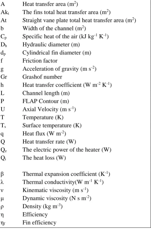
Nomenclature
A Heat transfer area (m2)
Akt The fins total heat transfer area (m2)
At Straight vane plate total heat transfer area (m2)
b Width of the channel (m2)
Cp Specific heat of the air (kJ kg-1 K-1)
Dh Hydraulic diameter (m)
dp Cylindrical fin diameter (m)
f Friction factor
g Acceleration of gravity (m s-2)
Gr Grashof number
h Heat transfer coefficient (W m-2 K-1)
L Channel length (m) P FLAP Contour (m) U Axial Velocity (m s-1)
T Temperature (K) Ts Surface temperature (K)
q Heat flux (W m-2)
Q Heat transfer rate (W)
Qe The electric power of the heater (W)
Qi The heat loss (W)
β Thermal expansion coefficient (K-1)
λ Thermal conductivity(W m-1 K-1)
ν Kinematic viscosity (m s-1)
μ Dynamic viscosity (N s m-2)
ρ Density (kg m-3)
η Efficiency ηf Fin efficiency
References
[1] Ahmed HE, Ahmed MI. Thermal performance of annulus with its applications: A review. Renewable and Sustainable Energy Reviews (2016).
[2] Deb P, Biswas G, Mitra NK. Heat transfer and flow structure in lam-inar and turbulent flows in a rectangular channel with longitudinal vortices. International Journal of Heat and Mass Transfer (1995)
38(13):2427–2444.
[3] Floryan JM, Novak M. Free convection heat transfer in multiple ver-tical channels. International Journal of Heat and Fluid Flow (1995)
16(4):244–253.
[4] Kotcioglu I, Bölükbaşı A. Experimental Investigation Heat Transfer In Different Winglet-Surfaces In A Verttical Rectangular Duct. DEÜ Mühendislik Fakültesi Fen ve Mühendislik Dergisi (2003) 5(2):89– 102.
[5] Kotcioglu I, Cansiz A, Khalaji MN. Experimental investigation for optimization of design parameters in a rectangular duct with plate-fins heat exchanger by Taguchi method. Applied Thermal Engineer-ing (2013) 50(1):604–613.
[6] Briggs DC, London AL. The heat transfer and flow friction charac-teristics of five offset rectangular and six plain triangular plate-fin heat transfer surfaces. Stanford, Calif.: Stanford University. Dept. of Mechanical Engineering (1960). viii, 74.
[7] Kotcioglu I, Ayhan T, Olgun H, Ayhan B. Heat transfer and flow structure in a rectangular channel with wing-type vortex generator. Turkish Journal of Engineering and Environmental Sciences (1998)
22(3):185–196.
[9] Masao F, Yu S, Goro Y. Heat transfer and pressure drop of perfo-rated surface heat exchanger with passage enlargement and contrac-tion. International Journal of Heat and Mass Transfer (1988)
31(1):135–142. doi:10.1016/0017-9310(88)90230-X.
[10] Caliskan S, Nasiri Khalaji M, Baskaya S, Kotcioglu I. Design Anal-ysis of Impinging Jet Array Heat Trans-fer From a Surface With V-Shaped and Convergent–Divergent Ribs by the Taguchi Method. Heat Transfer Engineering (2016) 37(15):1252–1266.
[11] Sparrow EM. Periodically Conwerging-Diverging Tubes and Their Turbulent Heat Transfer Pressure Drop, Fluid Flow, and Enhance-ment Characteristics. Journal of Heat Transfer (1984) 106(1):55-63. [12] Garg VK, Maji PK. Laminar flow and heat transfer in a periodically
converging‐diverging channel. International Journal for Numerical Methods in Fluids (1988) 8(5):579–597.
[13] Balasundar P, Sastri VM. Natural convection heat transfer in over-lapping discrete plate arrays. International Journal of Heat and Mass Transfer (1994) 37:107–111.
[14] Sahin HM, Dal AR, Baysal E. 3-D Numerical study on the correla-tion between variable inclined fin angles and thermal behavior in plate fin-tube heat exchanger. Applied Thermal Engineering (2007)
27(11):1806–1816.
[15] Ozceyhan V, Gunes S, Buyukalaca O, Altuntop N. Heat transfer en-hancement in a tube using circular cross sectional rings separated from wall. Applied Energy (2008) 85(10):988–1001.
doi:10.1016/j.apenergy.2008.02.007.
[16] Hsieh S-S, Liu M-H, Wu F-Y. Developing turbulent mixed convec-tion in a horizontal circular tube with strip-type inserts. International Journal of Heat and Mass Transfer (1998) 41(8-9):1049–1063. doi:10.1016/S0017-9310(97)00181-6.
[17] Promvonge P. Thermal augmentation in circular tube with twisted tape and wire coil turbulators. Energy Conversion and Management (2008) 49(11):2949–2955. doi:10.1016/j.enconman.2008.06.022. [18] Eiamsa-ard S, Promvonge P. Experimental in-vestigation of heat transfer and friction characteristics in a circular tube fitted with V-nozzle turbulators. International Communications in Heat and Mass Transfer (2006) 33(5):591–600.
[19] Eiamsa-ard S, Promvonge P. Enhancement of heat transfer in a tube with regularly-spaced helical tape swirl generators. Solar Energy (2005) 78(4):483–494. doi:10.1016/j.solener.2004.09.021. [20] Yakut K, Sahin B. The effects of vortex characteristics on